Passive reverberation nulling for target enhancement H. C. Song,a兲 W. S. Hodgkiss, W. A. Kuperman, K. G. Sabra, and T. Akal Marine Physical Laboratory, Scripps Institution of Oceanography, La Jolla, California 92093-0238, USA
M. Stevenson NATO Undersea Research Centre, La Spezia, Italy
共Received 19 December 2006; revised 29 May 2007; accepted 25 September 2007兲 Echo-to-reverberation enhancement previously has been demonstrated using time reversal focusing when knowledge of the channel response between a target and the source array elements is available. In the absence of this knowledge, direct focusing is not possible. However, active reverberation nulling still is feasible given observations of reverberation from conventional source array transmissions. For a given range of interest, the response between the source array elements and the dominant sources of boundary reverberation is provided by the corresponding reverberation from this range. Thus, an active transmission can be projected from the source array which minimizes the energy interacting with the boundaries at a given range while still ensonifying the waveguide between the boundaries. As an alternative, here a passive reverberation nulling concept is proposed. In a similar fashion, the observed reverberation defines the response between the source array elements and the dominant sources of boundary reverberation at each range and this is used to drive a range-dependent sequence of projection operators. When these projection operators subsequently are applied to the received data vectors, reverberation can be diminished. The improvement in target detectability is demonstrated using experimental data with an echo repeater simulating the presence of a target. © 2007 Acoustical Society of America. 关DOI: 10.1121/1.2799508兴 PACS number共s兲: 43.30.Gv, 43.30.Hw 关DRD兴
I. INTRODUCTION
Reverberation from rough ocean boundaries often limits the performance of active sonar systems in shallow water environments.1 Recently, a time reversal 共TR兲 approach for reverberation mitigation has been investigated in theory2 and subsequently demonstrated experimentally3 to reduce prominent reverberation returns by retransmission from a time reversal mirror 共TRM兲. The basic idea is that a time-gated portion of reverberation provides the transfer function between the TRM and the sea surface/bottom boundaries for a given range cell, which can be exploited either for focusing back to the corresponding interface4,5 or reverberation nulling.2,3 The motivation behind reverberation nulling is to minimize the acoustic energy incident on the boundaries in a specific range cell while still projecting energy into the water column for the ensonification of targets. Reverberation nulling occurs naturally with the TR method when focusing acoustic energy on a target due to shadowing of the boundaries below and above the focus in a waveguide 共see Fig. 2共b兲 in Ref. 6兲. Indeed, Kim et al.6 demonstrated the potential of echo-to-reverberation enhancement using the TR approach over a simple broadside 共BS兲 transmission. First, with a probe source 共PS兲 at 4.7 km range from the TRM in 110-m-deep water, the increased level of ensonification at the PS and the decreased level of reverberation at the TRM were measured separately and combined to esti-
a兲
Author to whom correspondence should be addressed. Electronic mail:
[email protected]
3296
J. Acoust. Soc. Am. 122 共6兲, December 2007
Pages: 3296–3303
mate the monostatic echo-to-reverberation enhancement. Second, improved target detectability was confirmed bistatically using an artificial target of unknown target strength 共TS兲 located next to the PS. Here, “monostatic” and “bistatic” refer to the use of a receiving array collocated with or separated from the source array. In Sec. III, we will show the results of a monostatic echo-to-reverberation enhancement experiment as opposed to our earlier bistatic demonstration.6 Although TR focusing is a useful demonstration of waveguide physics, it is unlikely that the target actually will be in the immediate vicinity of a PS.7 In this case, it is not possible to focus directly on the target. If a priori knowledge of target range is available, however, focusing on a target still is feasible using an iterative time reversal approach without a PS by iteratively retransmitting a selected portion of data which contains the target echo.5,8 Instead of boosting the target echo by TR focusing, we also can achieve echo-to-reverberation enhancement by actively reducing the reverberation given observations of reverberation from conventional source array transmissions. In this paper, the terms “active” and “passive” refer to the TRM: “active” when a TRM attempts to focus on a target or null out reverberation by transmitting an environmentally dependent excitation vector signal while “passive” when a TRM simply transmits conventional BS signals followed by processing of the returned time series. For a given range of interest, the response between the source array elements and the dominant sources of boundary reverberation is provided by the corresponding reverberation from this range. Thus, an active transmission can be projected from the source array which minimizes the energy interacting with the boundaries
0001-4966/2007/122共6兲/3296/8/$23.00
© 2007 Acoustical Society of America
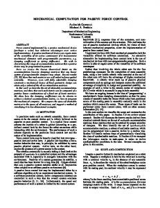
FIG. 1. 共Color online兲 Experimental configuration for reverberation measurements carried out north of Elba Island off the west coast of Italy. The echo repeater 共ER兲 was deployed from the R/V Alliance at 70 m depth and about 3 km away from the SRA. The ER was drifting along with the R/V Alliance.
at a given range while still ensonifying the waveguide between the boundaries.2 While active reverberation nulling also has been demonstrated experimentally,3 the range over which boundary interaction is suppressed is limited and thus different excitation vectors must be transmitted for each range unless the specific range of a target is known. As an alternative, we consider a passive reverberation nulling concept which operates only on the returning reverberation from conventional source array transmissions without a PS and a priori knowledge of target range. In a similar fashion, the observed reverberation defines the response between the source array elements and the dominant sources of boundary reverberation at each range. A collection of targetfree responses can be used to drive a range-dependent sequence of projection operators based on the eigendecomposition of the data covariance matrix.9,10 When these projection operators subsequently are applied to the received data in the presence of a target, reduction of reverberation results in enhancing the target echo. This approach essentially is equivalent to the eigenvector-based projection method in radar10–13 where strong interferences are suppressed by projecting the array data onto the subspace that is orthogonal to the interference subspace. In reverberationlimited active sonar conditions,1 reverberation can be treated as a strong interference although it represents a collection of distributed sources at the interface rather than a single point source. Despite the analogy, we are not aware of any previous work reported in the literature applying the projection approach to low or mid-frequency reverberation nulling. Hodgkiss and Alexandrou14 proposed an adaptive leastsquares algorithm to reject high-frequency under-ice reverberation, while Cox15 exploited Doppler and applied an adaptive beamforming algorithm with a towed horizontal array to detect a weak moving target in the presence of strong bottom reverberation. This paper is organized as follows. Section II describes the reverberation experiment conducted during FAF-04. Section III demonstrates monostatic echo-to-reverberation enhancement of the TR approach using an echo repeater simulating a target. Finally, Sec. IV demonstrates improved target detectability resulting from the passive reverberation nulling approach. II. REVERBERATION EXPERIMENT
A time reversal experiment 共FAF-04兲 was conducted jointly with the NATO Undersea Research Center in July 2004 both north and south of Elba Island, off the west coast J. Acoust. Soc. Am., Vol. 122, No. 6, December 2007
of Italy. The reverberation experiment reported in this paper was carried out in a flat region of 120-m-deep water north of Elba on July 22 共JD204兲. The source-receive array 共SRA or TRM兲 consists of 29 transducers spanning a 78 m aperture 共2.786 m interelement spacing from 32 to 110 m兲 as shown in Fig. 1. The maximum source level of each element was 178 dB re 1 Pa. An echo repeater 共ER兲 simulating a target was deployed at 70 m depth which was drifting along with the R/V Alliance. The target strength 共TS兲 of the ER was set to 30 dB. A sound speed profile collected during the experiment is displayed in Fig. 2 featuring an extended thermocline down to 70 m depth. We confine our interest to narrowband continuous wave 共cw兲 pulses as in our previous papers.2,3,6 III. ECHO-TO-REVERBERATION ENHANCEMENT
In this section, monostatic echo-to-reverberation enhancement is demonstrated using the echo repeater shown in Fig. 1. First, consider a conventional BS transmission as a base line. The SRA simply transmits a 100 ms cw pulse at 3500 Hz on all elements simultaneously and that BS transmission is captured by the ER. Next, the SRA repeats the BS transmission while the ER transmits the previously captured signal simultaneously with an appropriate time delay simulating a target echo. Immediately after the BS transmission,
FIG. 2. The sound speed profile measured during the reverberation experiment on July 22, 2004 共JD204兲 along with the depth coverage of the sourcereceive array 共SRA兲. The downward refracting profile with an extended thermocline down to 70 m depth suggests that the reverberation return mainly is due to interaction with the bottom. Song et al.: Passive reverberation nulling
3297
the SRA starts recording the monostatic reverberation return which contains the target echo as well. An example of the measured monostatic reverberation field at the SRA plus ER transmission is shown in Fig. 3共a兲 when the ER was about 3 km away from the SRA. Note that three of the SRA transducers 共Channels 7, 22 and 25 from the bottom兲 were disabled during the experiment indicated in thick blue horizontal lines in Figs. 3共a兲 and 3共b兲. Next, consider the case of TR implementing active focusing. A 100 ms cw pulse at 3500 Hz is transmitted initially from the ER 共acting as a PS兲, and is received and time reversed by the SRA. The time-reversed signal from the SRA then is refocused on and captured by the ER. As in the BS transmission, the SRA repeats the TR transmission while the ER transmits the captured signal with an appropriate time delay. The monostatic reverberation field plus ER transmission recorded by the SRA is shown in Fig. 3共b兲. The presence of a target around 3.7 s corresponding to the ER range of 3 km is indicated clearly as opposed to Fig. 3共a兲 where the target echo is hardly visible. Note that the dynamic range of Fig. 3共a兲 is 5 dB higher than that of Fig. 3共b兲 due to the difference in the transmitted level. In other words, approximately 5 dB less energy is transmitted by the SRA for the TR transmission compared to the conventional BS transmission as previously observed in Ref. 6. Finally, Fig. 3共c兲 shows a comparison between the BS and TR transmissions. The levels are obtained by incoherent averaging of the 26 active channels. The TR level 共red兲 has been increased by 5 dB to compensate for the lower level transmission by the SRA. The echo-to-reverberation enhancement is about 7 – 8 dB over the BS transmission in addition to an overall reverberation reduction of 5 dB. This result is consistent with the one reported in Ref. 6 where the increased ensonification level at the target 共5 dB兲 and the decreased reverberation level 共3 dB兲 were measured separately without using an echo repeater. IV. PASSIVE REVERBERATION NULLING
Although the active TR focusing approach shows a significant echo-to-reverberation enhancement, it is assumed that the channel response from a target is known to the SRA by using a probe source in the vicinity of the target.6,7 If a priori knowledge of target range is available, either active reverberation nulling2 or an iterative time reversal approach8 still can be employed to enhance the target echo as described in Sec. I. In this section, we consider the more typical situation where neither a PS nor a priori knowledge of target range is available. Here we propose a passive reverberation nulling approach to improve target detection from BS transmissions containing a target echo as shown in Fig. 3共a兲. The approach essentially is equivalent to the orthogonal projection methods found in adaptive beamforming algorithms10,13 where strong interferers are suppressed. During the FAF-04 reverberation experiment described in Sec. II, a 100 ms cw BS transmission was carried out every 15 s over approximately 4 min 共JD204 11:20:1511:23:45兲 while the ER at 3 km range retransmitted the captured echo every other BS transmission 共i.e., 30 s兲. As a 3298
J. Acoust. Soc. Am., Vol. 122, No. 6, December 2007
FIG. 3. Measured backscattered field at the SRA when the ER transmission simulating a target is present: 共a兲 BS transmission and 共b兲 TR transmission. Note that the BS dynamic range is 5 dB higher than that of TR due to the difference in the transmitted level. Plot 共c兲 shows the corresponding reverberation level incoherently averaged across the array elements where the TR curve is offset by 5 dB for comparison purposes. The TR result clearly shows the presence of a target around 3.7 s corresponding to the ER range of 3 km at this time.
result, a total of 16 BS reverberation returns were collected, half of which included the target echo as well. Without any signal processing, the incoherent reverberation levels are shown in the upper left and right panels of Fig. 4: 共a兲 reverberation alone and 共b兲 echo plus reverberation. Interestingly, the target at around 3.9 s happens to occur very close to the strong reverberation return around 4.1 s, making it difficult to determine the presence of the target in Fig. 4共b兲. We also Song et al.: Passive reverberation nulling
FIG. 4. Reverberation returns from BS transmissions before 共top兲 and after 共bottom兲 passive reverberation nulling 共see text for details兲. The upper two plots display the incoherent average of reverberation levels: 共a兲 reverberation alone and 共b兲 echo plus reverberation. The target echo should be around 3.9 s 共arrow兲. The lower two plots show the results after reverberation nulling has been applied to: 共c兲 reverberation alone when r = x and 共d兲 echo plus reverberation when r = s + x. Plot 共d兲 shows improved target detectability resulting from reverberation nulling over plot 共b兲 before nulling. Note that after reverberation nulling the absolute level has no meaning in the lower two plots.
will show results of target detection from echo plus reverberation returns later in Sec. IV B. Note that this portion of the experiment was carried out half an hour earlier than the monostatic echo-to-reverberation data collection reported in Sec. III where the ER is at around 3.7 s. The BS transmission loss 共TL兲 from the SRA is displayed in Fig. 5共a兲 indicating that the reverberation return mainly is due to interaction with the sea floor in a downward refracting environment 共see Fig. 2兲. Here we do not attempt to reproduce the experimental results shown in Fig. 4共a兲 关or Fig. 5共b兲兴 except to capture the general features of reverberation from a propagation perspective. A. Projection operator
The basic idea behind reverberation nulling is based on the observation that in the absence of a target s, a timeJ. Acoust. Soc. Am., Vol. 122, No. 6, December 2007
windowed segment of reverberation data transformed into the frequency domain x can be represented as 共1兲
x = h + n,
where h the transfer function vector between a TRM array and the corresponding sea surface and/or bottom boundaries for that range cell.2 Note that h incorporates the reverberation scattering strength as well as the source level as a scale factor. The additive white noise n is assumed uncorrelated with the reverberation h. Here boldface lower case letters denote N-dimensional vectors and N is the number of TRM elements. In practice, a number of target-free reverberation returns x j 共i.e., snapshots兲 are collected to form a data covariance ˆ and its eigen-decomposition: matrix R Song et al.: Passive reverberation nulling
3299
ˆ from a FIG. 6. Eigenvalue spread 共1–5兲 of the data covariance matrix R total of eight 共L = 8兲 target-free snapshots 共BS transmissions兲 as a function a time. The first eigenvalue 共top兲 is about 10 dB higher than the second. As a reference, the average of the incoherent energy from Fig. 4共a兲 is superimposed with an offset of 80 dB 共dotted line兲 below the first eigenvalue. The similarity between the first eigenvalue and the average indicates that the first eigenvalue captures the reverberation component.
FIG. 5. 共Color online兲 共a兲 BS transmission loss 共TL兲 from the SRA using the sound speed profile displayed in Fig. 2 共b兲 Reverberation return shown in Fig. 4共a兲. The two plots are lined up approximately by the corresponding round-trip travel time. The TL plot indicates that the reverberation return mainly is due to interaction with the sea floor including the peak at around 4.1 s.
values, and U an N ⫻ K matrix of the corresponding eigenvectors 共ui, i = 1 , . . . , K兲 spanning the K-dimensional reverberation subspace. Some of the eigenvalues may be zero so ˆ may be less than full 共e.g., for a snapshot-deficient that R case when L ⬍ N兲.16 For reverberation nulling, a complementary subspace that is orthogonal to the reverberation subspace is obtained in terms of an N ⫻ N projection matrix P such that13 K
ˆ =1 R L
兺
x jxHj
H
H
= U⌳U + V⍀V ,
共2兲
where H denotes a conjugate transpose, L the number of snapshots, ⌳ a diagonal matrix containing K largest eigen-
P = I − UUH = I − 兺 uiuH i ,
共3兲
i=1
where I is an identity matrix. It should be mentioned that the ˆ projection matrix can be deduced from the inverse of R
FIG. 7. Echo-to-reverberation enhancement after reverberation nulling for different numbers of snapshots: 共a兲 L = 1 and 共b兲 L = 8. The improvement with more snapshots is visible. K = 1 is used. 3300
J. Acoust. Soc. Am., Vol. 122, No. 6, December 2007
Song et al.: Passive reverberation nulling
ˆ from a FIG. 8. Eigenvalue spread 共1–5兲 of the data covariance matrix R total of eight 共L = 8兲 echo plus reverberation returns as a function a time. The first eigenvalue looks similar to the one shown in Fig. 6. The incoherent average of the energy from Fig. 4共a兲 is superimposed with an offset of 80 dB 共dotted line兲. On the other hand, the second eigenvalue shows a strong peak at 3.9 s at the range of the target.
which arises in adaptive algorithms when the 共N − K兲 small eigenvalues are negligible as compared to the K significant eigenvalues.9 ˆ will be equal to 1 共i.e., K = 1兲 in a Ideally the rank of R stationary environment since reverberation is treated as a single interference in Eq. 共1兲. Thus, the first eigenvector u1 will be proportional to the transfer function vector h. For a single snapshot case 共L = 1兲, u1 is assumed approximately proportional to the transfer function vector h for a high reverberation-to-noise ratio.2,3 Our experiment produced eight target-free snapshots 共L = 8兲 while the ER simulating a target was drifting along with the R/V Alliance. For a small
number of snapshots, the first eigenvector alone may not necessarily represent the reverberation subspace due to eigenvalue spreading.10 Since target-free observations are used to construct the projection matrix and the number of snapshots 共L = 8兲 is much smaller than the number of degrees of freedom 共DOF兲 equal to the number of active array elements 共N = 26兲, any number of K ⱕ L can be used for the reverberation subspace which is confirmed in Sec. IV B. This is not surprising because the 26-element array covers the water column and provides the spatial diversity17 which allows for simultaneous focusing 共or localization兲 on a target within the water column and the bottom interface. In other words, all the target-free reverberation is confined to the bottom interface and the remaining 共N − L兲 DOF subspace is sufficient to capture the signal component which is orthogonal to the reverberation. When the echo plus reverberation returns are used to construct the projection matrix, however, K must be chosen carefully as discussed in the next subsection. Below we investigate the impact of L, K, as well as N on the detection performance using the 16 BS transmission data. B. Target detection
The projection matrix P can be applied directly to echo plus reverberation data in order to improve the target detectability. Since a priori knowledge of target range is not assumed, each segment of the reverberation data is transformed into the frequency domain by fast Fourier transform and is advanced by a sliding 共moving兲 window. Specifically, the duration of the time window ⌬ is selected 1.3 times the pulse length = 100 ms as suggested in Ref. 2 and each segment is advanced by 25 ms. Figure 6 shows the first five eigenvalues of the data ˆ as a function of time 共or equivalently covariance matrix R range兲 from the eight target-free BS transmissions 共L = 8兲 displayed in Fig. 4共a兲. As expected for a strong single interfer-
FIG. 9. Echo-to-reverberation enhancement after reverberation nulling from eight 共L = 8兲 echo plus reverberation snapshots: 共a兲 K = 1 and 共b兲 K = 3. K = 1 still provides target detection comparable to one in Fig. 4共d兲 which uses target-free observations. However, the detection performance deteriorates with K = 3 by rejecting the signal component as well. J. Acoust. Soc. Am., Vol. 122, No. 6, December 2007
Song et al.: Passive reverberation nulling
3301
imposed with an offset of 80 dB below the first eigenvalue. It follows closely the first eigenvalue confirming that the first eigenvalue captures the reverberation. Due to the large number of DOF 共N = 26兲 and small number of snapshots 共L = 8兲 as discussed in Sec. IV A, it is found that any number of K ⱕ 8 provides similar performance. The lower two plots of Fig. 4 show the results after reverberation nulling 储Pr储 using K = 3: 共c兲 reverberation alone when r = x and 共d兲 echo plus reverberation when r = s + x. Two observations can be made. First, the prominent reverberation returns in Fig. 4共a兲 have diminished and are flattened out in Fig. 4共c兲. Second, plot 共d兲 clearly demonstrates improved target detectability after nulling at around 3.9 s 共about 5 dB over the background兲 as compared to plot Fig. 4共b兲 before reverberation nulling. Note that after the projection operation the absolute level 共dB兲 has no meaning in the lower two plots. It also should be mentioned that the passive reverberation nulling approach can be applied even when multiple targets are present at various ranges. The impact of the number of snapshots L is illustrated in Fig. 7 which compares results when 共a兲 L = 1 and 共b兲 L = 8. Since only a single eigenvalue is available for L = 1, K = 1 is applied to both cases for comparison purposes. While a single snapshot still provides reasonable performance suggesting a high reverberation-to-noise ratio of the data, the improvement using more snapshots is evident in Fig. 7共b兲. Up to now, it is assumed that the target-free observations ˆ and are available to construct the data covariance matrix R then the projection matrix for nulling. In practice, however, we may not know whether the measured reverberation contains a target echo. Consider the case when we have a total of eight echo plus reverberation returns. The observation vector then can be written as x = h + s + n.
FIG. 10. Echo-to-reverberation enhancement after reverberation nulling for different numbers of receive array elements: N = 26 共full兲, N = 14 共half兲, and N = 6 共quarter兲. The array elements are selected from the bottom. K = 1 and L = 8 from target-free observations. Half the array N = 14 still shows a target echo at 3.9 s while a false target emerges at around 2.1 s.
ence, the first eigenvalue is dominant and is about 10 dB higher than the second eigenvalue. The dotted line represents the average level of the incoherent energy in Fig. 4共a兲 super3302
J. Acoust. Soc. Am., Vol. 122, No. 6, December 2007
共4兲
If the eigenvalues corresponding to reverberation and signal are separable, a projection matrix still can be derived by selecting an appropriate number of K such that the K-dimensional subspace spans the reverberation alone but excludes the signal component.10 The first five eigenvalues are shown in Fig. 8 from the eight 共L = 8兲 echo plus reverberation returns. The first eigenvalue looks about the same as one in Fig. 6. On the other hand, the second eigenvalue shows a strong peak around at 3.9 s. This suggests that the first eigenvector K = 1 spans the reverberation space while the second eigenvector represents the target space. Figure 9 compares results when 共a兲 K = 1 and 共b兲 K = 3 are employed to construct the projection matrix which is then applied to the individual echo plus reverberation returns. K = 1 shows target detection comparable to the result shown in Fig. 4共d兲 which uses target-free observations. On the other hand, the detection performance deteriorates with K = 3 since the resulting projection matrix rejects the target component as well. Finally, we investigate the impact of the number of array elements used for processing the received time series. Recall that the full source array was used for the BS transmissions. Figure 10 shows the performance when N = 26 共full兲, N = 14 共half兲, and N = 6 共quarter兲. The array elements are selected Song et al.: Passive reverberation nulling
from the bottom. The eight 共L = 8兲 target-free snapshots are used to construct the data covariance matrix as before and K = 1. Half the array 共N = 14兲 still shows target detection at 3.9 s while a false target emerges at around 2.1 s as well. With a further decrease down to N = 6, the target echo eventually disappears and the distinct peak at 2.1 s likely would lead to a false alarm. V. CONCLUSION
Bottom backscattering potentially can be used as a surrogate probe source for reverberation nulling. A time-gated portion of the reverberation return from conventional BS transmissions provides an estimate of the transfer function between a TRM array and the corresponding range cell boundaries. Active reverberation nulling projects an excitation weight vector that is in the complementary subspace orthogonal to the focusing vector, minimizing the acoustic energy interacting with the boundaries in a specific range cell. However, the range over which boundary interaction is suppressed is limited and different excitation vectors must be transmitted for each range of interest. Alternatively, passive reverberation nulling applies an orthogonal projection onto the echo plus reverberation data to suppress the reverberation component without need for a specialized active retransmission. The signal processing employed essentially is equivalent to the orthogonal projection method developed in adaptive beamforming algorithms. The improved target detection resulting from passive reverberation nulling is demonstrated experimentally with reverberation data and an echo repeater simulating a target in shallow water. ACKNOWLEDGMENT
This work was supported by the Office of Naval Research under Contract No. N00014-01-D-0.043-D06.
J. Acoust. Soc. Am., Vol. 122, No. 6, December 2007
R. Urick, Principles of Underwater Sound 共McGraw–Hill, New York, 1983兲. 2 H. C. Song, S. Kim, W. Hodgkiss, and W. A. Kuperman, “Environmentally adaptive reverberation nulling using a time reversal mirror,” J. Acoust. Soc. Am. 116, 763–768 共2004兲. 3 H. C. Song, W. Hodgkiss, W. A. Kuperman, P. Roux, T. Akal, and M. Stevenson, “Experimental demonstration of adaptive reverberation nulling using time reversal,” J. Acoust. Soc. Am. 118, 1381–1387 共2005兲. 4 J. F. Lingevitch, H. C. Song, and W. A. Kuperman, “Time reversed reverberation focusing in a waveguide,” J. Acoust. Soc. Am. 111, 2609–2614 共2002兲. 5 K. G. Sabra, P. Roux, H. C. Song, W. S. Hodgkiss, W. Kuperman, T. Akal, and M. Stevenson, “Experimental demonstration of iterative time-reversed reverberation focusing in a rough waveguide: Application to target detection,” J. Acoust. Soc. Am. 120, 1305–1314 共2006兲. 6 S. Kim, W. A. Kuperman, W. S. Hodgkiss, H. C. Song, G. F. Edelmann, and T. Akal, “Echo-to-reverberation enhancement using a time reversal mirror,” J. Acoust. Soc. Am. 115, 1525–1531 共2004兲. 7 H. C. Song, W. A. Kuperman, and W. S. Hodgkiss, “A time-reversal mirror with variable range focusing,” J. Acoust. Soc. Am. 103, 3234–3240 共1998兲. 8 H. C. Song, W. A. Kuperman, W. S. Hodgkiss, T. Akal, C. Ferla, and D. R. Jackson, “Iterative time reversal in the ocean,” J. Acoust. Soc. Am. 105, 3176–3184 共1999兲. 9 H. Cox and R. Pitre, “Robust dmr and multi-rate adaptive beamforming,” in Proceedings of 31st Asilomar Conference, 920–924 共1997兲. 10 H. Cox, “Multi-rate adaptive beamforming 共MRABF兲,” in Sensor Array and Multichannel Signal Processing Workshop, 306–309 共2000兲. 11 T. Citron and T. Kailath, “Eigenvector methods and beamforming—a first approach,” in Proceedings of 17th Asilomar Conference 共1983兲. 12 I. Kirsteins and D. Tufts, “On the probability density of signal-to-noise ratio in improved adaptive detector,” in Proceedings of ICASSP-85, 572– 575 共1985兲. 13 A. Gershman, V. Turchin, and V. Zverev, “Experimental results of localization of moving underwater signal by adaptive beamforming,” IEEE Trans. Signal Process. 43, 2249–2257 共1995兲. 14 W. Hodgkiss and D. Alexandrou, “Under-ice reverberation rejection,” IEEE J. Ocean. Eng. OE-10, 285–289 共1985兲. 15 H. Cox, “Space-time processing for suppression of bottom reverberation,” in Proceedings of 29th Asilomar Conference, 1296–1299 共1996兲. 16 H. C. Song, W. A. Kuperman, W. Hodgkiss, P. Gerstoft, and J. Kim, “Null broadening with snapshot-deficient covariance matrices in passive sonar,” IEEE J. Ocean. Eng. 28, 250–261 共2003兲. 17 P. Roux, W. Kuperman, W. Hodgkiss, H. Song, T. Akal, and M. Stevenson, “Non-reciprocal implementations of time reversal in the ocean,” J. Acoust. Soc. Am. 116, 1009–1015 共2004兲. 1
Song et al.: Passive reverberation nulling
3303