Path Computation Element in Telecom Networks: Recent Developments and Standardization Activities V. L´opez † , B. Huiszoon † , J. Fern´andez-Palacios§ , O. Gonz´alez de Dios§ , and J. Aracil †
†
High Performance Computing and Networking group, Universidad Aut´onoma de Madrid, 28049 Madrid, Spain. Email:
[email protected] § Telef´onica I+D, Calle Emilio Vargas 6, 28043 Madrid, Spain.
Abstract— This paper provides an overview of the recent developments in research and the IETF standardization body on using a path computation element in complex telecom networking scenarios such as the multi-layer and multi-domain cases. Implications on the control plane when using such element are addressed as well as the required protocol extensions. The emerging impairment-aware routing and wavelength assignment problem is extensively treated for networks using lightpaths.
NMS Path Request
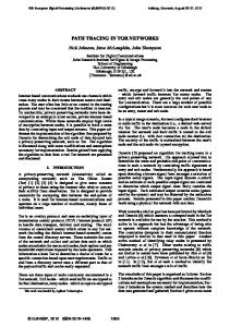
II. PATH C OMPUTATION E LEMENT: T HE BASICS The path computation element is “an entity (component, application, or network node) that is capable of computing a network path or route based on a network graph and applying computational constraints” [2]. This definition allows multiple configuration modes as explained in the following. A. Location The PCE can be part of the network management system (NMS) such that given a service request, the NMS requests a path to the PCE. The PCE requires the state information of the network which is stored in the traffic engineering database (TED). Once the PCE provides an answer to the NMS, the configuration is sent to the network elements to setup the service. This situation is depicted in Fig. 1
TED
Request Response Traffic Engineering Information
Path Establishment
I. I NTRODUCTION The recent attention that path computation element (PCE) architectures have received is mainly because of its potential to provide feasible solutions for multi-layer networks and to solve the interconnection of services into multiple domains [1]. In particular, complex routing problems emerge when lightpaths cross multiple domains combined with multi-layer traffic engineering. This work aims to provide an up to date overview of efforts made by the research community and the IETF standardization body to increase the performance of a complex PCE-based network architecture. The issues are considered both from the control and the management planes. The remaining is organized as follows: Section II provides the basics of the PCE and show its position in different kinds of networks. The PCE protocols are introduced as well as the efforts to extend these to support impairment-aware routing. Section III discusses the state-of-the-art in impairment-aware routing. The automation of the control and management plane based on a PCE is presented in section IV. Finally, the paper is summarized in section V.
PCE
Fig. 1.
Path computation element: Tool of the network management plane
Instead of adding the PCE functionality into the management plane (MP), the PCE can also be located into the control plane. If so, path computation client (PCC) is present which is an entity that requests paths to the PCE. Usually this PCC is an edge generalized multi-protocol label switching (GMPLS) router that can compute the route in a distributed way using standard GMPLS routing algorithms or it can request a path to the PCE when the routing algorithm is not standard. The PCE can be located with the PCC or it can be a separate server. Both cases are shown in Fig. 3 (a) and (b). The collocated solution is easier to implement and it does not require a request/response standard solution. On the other hand, the separated server solution uses the standard request/response protocol and it allows for a single PCE entity for multiple PCCs. B. Multi-layer and single-domain PCE interconnection There are two centralized and two distributed interconnection models for the PCE in multi-layer networks. The centralized models are the following two [3]: • Single multi-layer PCE: This architecture has a single PCE that is able to have information from all the layers in the network. This PCE may be located at any location in an integrated control plane or in the management plane. • PCE/virtual network topology manager (VNTM): The VNTM is the network topology shown to the upper layer [4] as shown in Fig. 2. The upper layer (IP; PCE) can ask for extra connections of the lower layer (optical cross connect, OXC; VNTM). Moreover, the VNTM could change the connections to the upper layer if its policies indicate that it is a better option. The operation mode of the VNTM could be any solution even using another PCE.
IP Router TE Information
PCE
TE Info
TED
OXC
PCE
VNT Manager Path Request
Fig. 2.
TE Information
PCE/VNTM configuration
TE Information
TED
Request Response
PCC
PCC
GMPLS
GMPLS
GMPLS
TED
Path Request
GMPLS
Network Element
(a) PCE co-located with the PCC
Fig. 3.
PCC
PCC
GMPLS
GMPLS
Network Element
•
Network Element
Fig. 4.
PCE in a multi-layer multi-domain network environment
Network Element
(b) PCE as separate server
Two different path computation element configurations
Regarding the distributed solutions for the PCE, the following two can be distinguished [3]: •
Network Element
Request /Response
PCC
Network Element
PCE
PCC
Network Element
GMPLS
Request /Response
PCE
PCE
Path Request
TED
Multiple cooperating single-layer PCEs: This option uses a PCE at each layer and they can exchange requests, when it is required. Because of this request exchange, the upper layer can ask for connections to the lower layer, so they can modify the upper layer topology. Besides, as there are two PCEs, this solution requires a lower computation complexity in the algorithms at each PCE. Multiple multi-layer PCE: This architecture has multiple multi-layer PCEs so all the PCEs have information about each layer in the network. The PCCs can request a path computation to any of the PCEs, but most likely the closest one. A second option is that the PCCs send queries to a given PCE which in turn can forward the request to any of the other PCEs, thus reducing computation time.
Authors in [5] compare some single-layer and multi-layer PCE architectural proposals, and [6] briefly describes the characteristics of 5 PCE approaches and assess them in terms of set-up delay. C. Multi-layer and multi-domain PCE interconnection The main motivation behind PCEs deployment is to tackle the problem of multi-domain label switched paths (LSPs) establishment. As a result, it is then possible to compute paths through multiple domains. The interconnection model for a multi-domain PCE scenario is shown in Fig. 4. Authors in [7] provide an overview of the developments in the area of PCE-based traffic engineering in GMPLS networks, analyze the PCE approach in multi-domain networks in detail, and compare its performance with existing solutions.
1. Path Request
Path Response
2. Path Establishment
Fig. 5.
3. Path Request
Path Response
4. Path Establishment Domain 2
Per-domain path computation by a PCE
Fig. 4 shows that there is at least one PCE at each domain and the interconnection model between the PCEs is based on the request/response protocol. When there is a request from the domain A to the domain B, the PCC sends the request to the PCE A, which forwards this request to PCE B. The PCE B provides a path or a failure in the procedure. This is the general procedure, but there are three different computation methods namely the per-domain path computation, simple cooperating PCEs and backward recursive path computation (BRPC). Each method is discussed in the following. 1) Per-domain path computation: At this approach, each PCE computes the path from its ingress to egress router in its domain. Consequently, all domains from the source to the destination must be known beforehand by the PCE in the source domain. This is an issue, since there is not a mechanism to choose the most suitable domains from the source to the destination. Moreover, if there are multiple connections between the domains, the PCE1 may provide a path that is optimal locally, but not overall (Fig 5). 2) Simple cooperating PCEs: The cooperating PCEs configuration allows the PCEs to exchange information in order to find a better end-to-end connection. Each PCE sends the best solution to the next PCE in the chain, but the neighboring PCE can suggest another connection to the former PCE. However, each connection is chosen locally which means that when the optimum end-to-end path does not use the local optimum paths, then the global solution cannot be found (Fig. 6).
2. Path Computation Domain 1
Top PCE
4. Path Computation Domain 2
Path Request
3. Path Request in Domain 2
1. Path Request In Domain 1
5. Path Response in Domain 2
6. Path Response in Domain 1
PCE 2
PCE 1 Node 1-2 A 8. Path Request in Domain 2
9. Path Response in Domain 2
Node 2-1 A
PCE 3 Node 2-3 A
Node 3-2 A Egress Node
Ingress Node
Node 1-2 B
Node 2-1 B
Node 2-3 B
Node 3-2 B
PCE 4 Node 4-1 A
7. Path Establishment in Domain 1
10. Path Establishment Domain 2
Fig. 6.
Simple cooperating PCEs PCE 2
PCE 1 Node 1-2 A
Node 2-1 A
Node 4-1 B
Fig. 8.
PCE 3 Node 2-3 A
Node 1-2 B
Fig. 7.
Node 2-1 B
Node 2-3 B
Node 4-3 B
Hierarchical multi-domain path computation element configuration
Node 3-2 A Egress Node
Ingress Node
Node 4-3 A
Node 3-2 B
Backward recursive path computation
3) Backward recursive path computation: The BRPC method starts at the destination domain, which sends to his neighbor the cost from the edge router to the destination node hence termed backwards [8]. As a result, the neighboring domain can create a tree with its egress nodes and the destination node. This process continues until the origin domain which then selects the best end-to-end path. Fig. 7 depicts three connected domains with one PCE per domain. Using BRPC, PCE1 sends a request to PCE2, which forwards it to the PCE3. The PCE3 replies with the distance from its border nodes (Q and R) with the domain 2. The PCE2 carries out the same operation sending a tree with the possible combinations from 1 to 3. When multiple domains are interconnected such information exchange can be complicated. If the intermediate domains are known, this process is easier. Border gateway protocols (BGPs) can be used to select the possible domains to check this PCE based computation. Unfortunately, BRPC does not scale with complex multi-domain topologies. Fig. 8 shows an example of a hierarchical PCE architecture. In this architecture there are some PCEs, and they are organized in multiple levels. Hierarchical PCEs do not have information of the whole network, but are only aware of the connectivity among the domains and provide coordination to the PCEs. The path request is sent to an upper-hierarchically PCE, which ask to the subsidiary PCE about their connectivity between the candidate inter-domain connections. Once this answer is known, the best solution is selected and it is transmitted to the source PCE. Such scenario is shown in Fig. 8. This hierarchical model fits with the model for the automatic switched optical network (ASON), since the networks are composed by sub-networks and the routing areas have relationship between peers. D. Discovery The previous architecture definition assumes that the PCCs are able to detect where the PCEs are located. However, such
assumption requires a mechanism to discover the PCEs that are operating in a given domain. Moreover, it is important to advertise the capabilities of each PCE. Such information allows PCCs and PCEs to carry out load balancing and to select the most appropriate computation algorithm for a given service. An option to solve this problem is to manually configure the PCCs, but this increases the management overhead. Extension of the interior gateway protocol (IGP) enables these functionalities. The extensions for “advertising optional router capabilities” in [9], [10] allow the open shortest path first (OSPF) and intermediate system-intermediate system (IS-IS) protocols to inform their neighbors with extra information. Moreover, these extensions are also included in [11], [12]. The information is included in type-length-value (TLV) objects, which inform about the IP address of the PCE, its operation domain, the neighbor domains. As a result, a PCC can select the most suitable PCE to solve a path computation request. E. PCEP Protocol and extensions to WSONs The path computation element protocol (PCEP) is a request/response based protocol. It is a session-based protocol and operates over the transport control protocol (TCP) [13], [14]. First the PCE and PCC open a session and they negotiate parameters by using seven possible messages namely Open, Keepalive, Request, Response, Notify, Error and Close. These are all used in six different situations denoted Session creation, Session keepalive, Patch computation, Notification messages, Error messages, and Session close [14]. Based on the description of the PCEP protocol, a PCC could be permanently connected to the PCE or only when there is a request. Depending on the number of requests, one solution can be more suitable than the other. PCEP may also be used between cooperating PCEs. In the following, the requirements are discussed in order to support wavelength switched optical networks (WSONs) by PCEP, and consequently to support PCE deployment in such network scenario [15]. 1) Resource allocation in WSONs: Currently, optical transport network (OTNs) are evolving from point-to-point (PTP) dense wavelength division multiplexing (DWDM) links to wavelength switched or routed optical networks (WSONs;
WRONs) where optical wavelengths may be all-optically switched or routed before being optically-electrically converted, optically converted to another wavelength, or 3R (reamplification, reshaping, retiming) regenerated. The path established by a single wavelength in a WSON is denoted as a lightpath because the wavelength passes through at least one optically transparent node. A lightpath is limited in its reach and therefore “islands of transparency” can be defined [16]. The growth in size of such islands is driven by reducing capital and operational expenditures in the network, i.e. in most cases it is cheaper to route the lightpaths in the optical domain instead of processing them at higher (electronic) layers. However, the all-optical routes give rise to a wavelength-continuity constraint in the network. It may be intuitively understood that impairments experienced by a lightpath during transmission may accumulate to unacceptable levels. So not only a routing and wavelength assignment (RWA) problem has to be solved, but also the impairments of the optical physical layer have to be taken as a constraint. In the latter case the RWA problem becomes the impairment-aware RWA (IA-RWA) problem. The RWA problem is well-known and can be solved using many different schemes [17] while the IA-RWA problem currently receives much interest. For example, [18], [19] present recent research on such algorithms. Which impairments of the optical layer should be taken in to account strongly depends on the reference network, the IA-RWA algorithm and the computational requirements of the PCE. 2) Extending PCEP for IA-RWA in WSONs: If PCEP is to support IA-RWA algorithms, it needs to fulfill additional requirements. The PCEP session initiated at the PCC should allow to set up a WSON RWA request and additional attributes are needed in the PCEP messages to allow for IV-information. 3) Computational requirements: The RFC [13] defines 6 types of objective functions that must be supported in a PCEP which are grouped by unsynchronized and synchronized functions. The former consists of the shortest path, least loaded path, and maximum available bandwidth path. The latter consists of minimize aggregate bandwidth consumption on all links, maximize the residual bandwidth on the most loaded link, and minimize the cumulative cost of a set of diverse paths. Then, the RFC [20] defines in detail that list of functions; however, as mentioned in [13] in section 5.1.14, new algorithms may be implemented without impacting PCEP. III. I MPAIRMENT- AWARENESS IN WSON S It is of increasing importance to monitor the status of the physical layer and to determine the influence of impairments on an ad-hoc or real-time basis such that this information can be taken into account when a routing decision has to be made. As mentioned in [21], the optical characteristics of the optical network elements should be made available to the entity which makes the IA-RWA decisions. Such entity can be a single PCE unit centrally located in the network or several PCEs in a cooperative way which store(s) the data in the TED. The most important linear impairments are optical signal to noise
ratio (OSNR), residual chromatic dispersion (CD), polarization mode dispersion (PMD) and cumulative penalties due to filter cascading or wavelength converters while also a large number of non-linear effects exist such as phase noise, self-phase and cross-phase modulation, and four-wave mixing [22]. It is common to take a single value for the linear and non-linear effects, in dB and rad/s respectively. Many vendors of stand-alone optical monitoring equipment can be found that monitor one or more of the following characteristics of the optical channel: the OSNR, the optical wavelength, and the optical power. The products are mostly denoted as optical channel monitoring (OCM) or optical performance monitoring (OPM) devices, and the output is mostly given on a per-wavelength basis. All routers are equipped with functionality to monitor the status of the optical links and typically a dedicated service channel is used to send this information across the link. An operator may have several modulation formats or bit rates active in its network, e.g. in case of a migration scenario or selected channel upgrading, so it may not be able to monitor all channels using a single OPM or OCM solution due to a trade-off between the cost and the performance of the devices. The main issue is the limited spectral resolution used (typically 0.1 nm) to reduce the costs, and different modulation formats used in adjacent wavelengths may then become undistinguishable, especially after traversing many fiber spans. Essentially, it is possible to measure the figures of merit simultaneously for different modulation formats [23]. The former may be a reason not to maintain a large variety in modulation formats in the network, and especially across adjacent lightpaths. Recently, the advances made in the processing power of analog-to-digital and digital-to-analog converters has enabled the usage of complex signal processing techniques in order to compensate for accumulated CD and PMD. In principle, electronic CD compensation can be done without deploying any dispersion compensating fiber along the transmission path, for example by using maximum likelihood sequence estimation [24]. Coherent detection in combination with digital signal processing is to become the de-facto means of transmission using advanced constellation modulation formats such as differential quadrature phase shift keying (DQPSK) on polarization multiplexed channels. These techniques provide a large throughput at moderate symbol rates with an increased robustness against optical impairments and/or compensation on a real-time basis. To that respect, these are powerful techniques to reduce the cost of the optical layer in an IARWA algorithm if several impairments are fully compensated for. Recent work shows a PCE test-bed, which computes wavelength routing with shared path projection [25]. Authors in [26] analyze a PCE-based solution to take optical link impairments into account during path computing in contrast to using the routing (OSPF-TE) or the signaling protocol (RSVP-TE) for this matter. A physical parameter database (PPD) is created which contains any type of information
PCEP
PCE
TED filled in with OSPF-TE
TED filled in with SNMP info PCE
PCC
OXC
SNMP manager
Equipment information
IP router
UNI
Management plane Control plane Data plane
Multi-layer capable router Network Element Controller
PCEP PCC
OXC IP router
UNI Control plane Data plane
Fig. 9.
PCE architecture based on GMPLS solutions
about the physical properties of the network links. In that paper, only link length is considered and optical time domain reflectometry is used to collect the information. Based on the architecture proposed in [26], [27] considers impairmentaware traffic engineering using a so-called signaling approach (SA; via OSPF or RSVP) or a PCE and include OSNR into the PPD. The main objective of that work is to compare the SA (centralized) and the PCE (distributed) approaches. IV. AUTOMATION OF THE CONTROL PLANE The PCE requires information about the network state for the path computation. Traditionally, such collection process is done using the link state protocols, but there are other alternatives [28]. GMPLS networks compute the paths based on the state information transmitted in a distributed way via the IGP, OSPF-traffic engineering (TE) or ISIS-TE. However, as PCE extends this computation process with more complex algorithms, it requires new information that may not be present at each network node. For instance, IA-RWA algorithms require some state information and the physical impairments which add more parameters to such computational process. In the definition of PCE architecture [2], there is no definition about how to fill in such TED. Authors in [28] propose alternatives to carry out such information collecting process. A. TED architectural solutions The main solution for filling TED is based on IGP-TE protocols. IGP-TE protocols exchange two kinds of information which is link state (LS) and TE, so two databases exist namely the link state database (LSDB) and the traffic engineering database (TED). The TED is a subset of the LSDB. The IP protocol only uses LS information, but MPLS and GMPLS can also use TE information next to LS information. Each node knows accurately the local link information; however, it should not be flooded across the network since not all nodes are interested on this information but only the PCEs. In GMPLS enabled networks, TE information is sent via the opaque link-state advertisements (LSA) [29]. This selective sharing information process reduces the requirements of the nodes in terms of CPU, bandwidth, etc. Additionally reutilizing IGP-TE protocols allows the integration with the currently deployed equipment in the networks. There are 3 ways to do such information exchange, namely 1) All PCEs informed, 2) A server informed, and 3) A PCE informed [28].
Multi-layer capable router Network Element Controller
Fig. 10.
PCE architecture operating in the management plane
B. Model based on GMPLS The GMPLS framework operates with a signaling protocol (RSVP-TE or CR-LDP) and an IGP-TE protocol (like ISIS-TE or OSPF-TE). Fig. 9 depicts how the PCE can be placed into the control plane. Accordingly, the PCE can sniff the LSA messages that are transmitted using OSPF-TE. In GMPLSenabled networks and when there is a new path request, it is made via the UNI interface as in Fig. 9. The edge routers should add the PCC functionalities, so they can request the PCE for the new path. Using the control plane links, the PCEP messages are transmitted. The RFC [30] defines the extension of OSPF to add traffic engineering capabilities to OSPF v2. The LSA messages are not modified in OSPF v3. The TE LSAs are sent frequently depending on their utilization. Even though GMPLS readily supports WSON signaling [31], [32], extensions are required to allow a specific identification of wavelengths and signals [33]. Nowadays, it is possible to select a wavelength using GMPLS, but extensions are required to send information on the modulation format and bit rate. C. Model based on SNMP Not all equipment readily deployed in the network is GMPLS enabled. It is possible to monitor the status of the network via SNMP protocol. Fig. 10 illustrates the PCE architecture when it is located into the management plane (MP). An SNMP manager is located in the MP and monitors the status of the network equipment. The TED can be filled using the information obtained via SNMP, i.e. the status of the IP and optical layer. The communication between the PCC and PCE remains similar to the GMPLS-based case. Once there is a path request from the UNI interface (or the NMS), the PCC requests a computation that is solved by the PCE. V. S UMMARY A detailed overview is provided of state-of-the-art in path computation elements to be placed in high capacity WDM networks using lightpaths by reviewing developments in research and activities in the IETF standardization body. The following topics are reviewed: multi-layer and multi-domain traffic engineering, implications on the control plane for GMPLS and SMNP, impairment-aware RWA, and the PCEP protocols.
ACKNOWLEDGEMENTS We gratefully acknowledge Jorge L´opez de Vergara for valuable discussions. This research was carried out with the support of BONE (“Building the Future Optical Network in Europe”), a Network of Excellence funded by the European Commission through the 7th ICT-Framework Programme, the Spanish Multilayer networks (TEC2008-02552-E) project and the Spanish MICINN Juan de la Cierva post-doc program. R EFERENCES [1] IETF PCE working group home page. Online (Dec. 2009): http://www.ietf.org/html.charters/pce-charter.html. [2] A. Farrel, J.P. Vasseur, and J. Ash, “A path computation element (PCE)based architecture,” IETF RFC 4655, pp. 1–40, August 2006. Online (Dec. 2009): http://tools.ietf.org/html/rfc4655. [3] E. Oki, T. Takeda, J.L. le Roux, and A. Farrel, “Framework for PCE-based inter-layer MPLS and GMPLS traffic engineering,” IETF RFC 5623, pp. 1–34, September 2009. Online (Dec. 2009): http://tools.ietf.org/html/rfc5623. [4] K. Shiomoto, D. Papadimitriou, J.L. le Roux, M. Vigoureux, and D. Brungard, “Requirements for GMPLS-based multi-region and multilayer networks (MRN/MLN),” IETF RFC 5212, pp. 1–28, July 2008. Online (Dec. 2009): http://tools.ietf.org/html/rfc5212. [5] F. Cugini, A. Giorgetti, N. Andriolli, F. Paolucci, L. Valcarenghi, and P. Castoldi, “Multiple path computation element (PCE) cooperation for multi-layer traffic engineering,” in Proc. OFC 2007, paper OWK5, March 2007, Anaheim, CA, USA. [6] S. Gunreben and F. Rambach, “Assessment and performance evaluation of PCE-based inter-layer traffic engineering,” in Proc. ONDM 2008, pp. 1-6, March 2008, Vilanova i la Geltr´u, Spain. [7] S. Dasgupta, J.C. de Oliveira, and J.P. Vasseur, “Path-computationelement-based architecture for interdomain MPLS/GMPLS traffic engineering: Overview and performance,” IEEE Network, vol. 21, no. 4, pp. 38–45, July 2007. [8] J.P. Vasseur, R. Zhang, N. Bitar, and J.L. le Roux, “A backwardrecursive PCE-based computation (BRPC) procedure to compute shortest constrained inter-domain traffic engineering label switched paths,” IETF RFC 5441, pp. 1–18, April 2009. Online (Dec. 2009): http://tools.ietf.org/html/rfc5441. [9] A. Lindem, N. Shen, J.P. Fasseur, R. Aggarwal, and S. Shaffer, “Extensions to OSPF for advertising optical router capabilities,” IETF RFC 4970, pp. 1–13, July 2007. Online (Dec. 2009): http://tools.ietf.org/html/rfc4970. [10] N. Shen, J.P. Fasseur, and R. Aggarwal, “Intermediate system to intermediate system (IS-IS) extensions for advertising router information,” IETF RFC 4971, pp. 1–9, July 2007. Online (Dec. 2009): http://tools.ietf.org/html/rfc4971. [11] J.L. le Roux, J.P. Fasseur, Y. Ikejiri, and R. Zhang, “OSPF protocol extensions for path computation element (PCE) discovery,” IETF RFC 5088, pp. 1–17, January 2008. Online (Dec. 2009): http://tools.ietf.org/html/rfc5088. [12] ——, “IS-IS protocol extensions for path computation element (PCE) discovery,” IETF RFC 5089, pp. 1–20, January 2008. Online (Dec. 2009): http://tools.ietf.org/html/rfc5089. [13] J. Ash and J.L. le Roux, “Path computation element (PCE) communication protocol generic requirements,” IETF RFC 4657, pp. 1–21, September 2006. Online (Dec. 2009): http://tools.ietf.org/html/rfc4657. [14] J.L. le Roux and J.P. Vasseur, “Path computation element (PCE) communication protocol,” IETF RFC 5440, pp. 1–87, March 2009. Online (Dec. 2009): http://tools.ietf.org/html/rfc5440. [15] Y. Lee, G. Bernstein, J. Martensson, T. Takeda, and T. Tsuritani, “PCEP requirements for WSON routing and wavelength assignment,” IETF RFC draft, pp. 1–16, September 2009. Work in progress (Dec. 2009): http://tools.ietf.org/html/draft-ietf-pce-wson-routing-wavelength-00. [16] A.A.M. Saleh, “Islands of transparency-an emerging reality in multiwavelength optical networking,” in Proc. IEEE/LEOS Summer Topical meeting on Broadband Optical Networks and Technologies, pp. 36, July 1998, Montrey, CA, USA. [17] H. Zang, J.P. Jue, and B. Mukherjee, “A review of routing and wavelength assignment approaches for wavelength-routed optical WDM networks,” Opt. Netw. Mag., no. 1, pp. 47–60, January 2000.
[18] M. Gagnaire and S. Al Zahr, “Impairment-aware routing and wavelength assignment in translucent networks: State of the art,” IEEE Commun. Mag., vol. 47, no. 5, pp. 55–61, May 2009. [19] K. Manousakis, K. Christodoulopoulos, E. Kamitsas, I. Tomkos, and E.A. Varvarigos, “Offline impairment-aware routing and wavelength assignment algorithms in translucent WDM optical networks,” IEEE/OSA J. Lightw. Technol., vol. 27, no. 12, pp. 1866–1877, June 15 2009. [20] J.L. le Roux, J.P. Vasseur, and Y. Lee, “Encoding of objective functions in the path computation element communication protocol (PCEP),” IETF RFC 5541, pp. 1–23, June 2009. Online (Dec. 2009): http://tools.ietf.org/html/rfc5541. [21] Y. Lee, G. Bernstein, and M. Kattan, “Information model for impaired optical path validation,” IETF RFC draft, pp. 1–18, July 2009. Work in progress (Dec. 2009): http://tools.ietf.org/html/draft-bernstein-wsonimpairment-info-02. [22] D. van den Borne, “Robust optical transmission systems: modulation and equalization,” Ph.D. dissertation, Eindhoven University of Technology, 2008. Available online: Eindhoven University Library. [23] Y.K. Lize, J. Yang, L.C. Christensen, X. Wu, S. Nuccio, T. Wu, A.E. Willner, R. Kashyap, and F. S´eguin, “Simultaneous and independent monitoring of OSNR, chromatic and polarization mode dispersion for NRZ-OOK, DPSK, and duobinary,” in Proc. OFC 2007, paper OThN2, March 2007, Anaheim, CA, USA. [24] M. Alfiad, D. van den Borne, A. Napoli, A.M.J. Koonen, and H. de Waardt, “A DPSK receiver with enhanced CD tolerance through optimized demodulation and MLSE,” IEEE Photon. Technol. Lett., vol. 20, no. 10, pp. 818–820, May 15 2008. [25] R. Casellas, R. Mu˜ noz, and R. Martinez, “A path computation element for shared path protection in GMPLS-enabled wavelength switched optical networks,” in Proc. ECOC 2008, paper Th.1.E.4, September 2008, Brussels, Belgium. [26] F. Cugini, F. Paolucci, L. Valcarenghi, and P. Castoldi, “Implementing a path computation element (PCE) to encompass physical impairments in transparent networks,” in Proc. OFC 2007, paper OWK6, March 2007, Anaheim, CA, USA. [27] P. Castoldi, et al., “Centralized vs. distributed approaches for encompassing physical impairments in transparent optical networks,” Lecture Notes in Computer Science, vol. 4534/2007, pp. 68–77, July 2007. [28] Y. Lee and G. Bernstein, “Alternative approaches to traffic engineering database creation and maintenance for path computation elements,” IETF RFC draft, pp. 1–20, May 2009. Work in progress (Dec. 2009): http://tools.ietf.org/html/draft-lee-pce-ted-alternatives-02. [29] L. Berger, I. Bryskin, A. Zinin, and R. Coltun, “The OSPF opaque LSA,” IETF RFC 5250, pp. 1–17, July 2008. Online (Dec. 2009): http://tools.ietf.org/html/rfc5250. [30] D. Katz, K. Kompella, and D. Yeung, “Traffic engineering (TE) extensions to OSPF version 2,” IETF RFC 3630, pp. 1–14, September 2003. Online (Dec. 2009): http://tools.ietf.org/html/rfc3630. [31] L. Berger, “Generalized multi-protocol label switching (GMPLS signaling functional description),” IETF RFC 3471, pp. 1–34, January 2003. Online (Dec. 2009): http://tools.ietf.org/html/rfc3471. [32] D. Papadimitriou, “Generalized multi-protocol label switching (GMPLS) signaling extensions for G.709 optical transport networks control,” IETF RFC 4328, pp. 1–23, January 2006. Online (Dec. 2009): http://tools.ietf.org/html/rfc4328. [33] Y. Lee and G. Bernstein, “Framework for GMPLS and PCE control of wavelength switched optical networks (WSON),” IETF RFC draft, pp. 1–45, September 2009. Work in progress (Dec. 2009): http://tools.ietf.org/html/draft-ietf-ccamp-rwa-wson-framework-03.