H. S. Ahn et al.: PDA-Based Mobile Robot System with Remote Monitoring for Home Environment
1487
PDA-Based Mobile Robot System with Remote Monitoring for Home Environment Ho Seok Ahn, In-Kyu Sa, and Jin Young Choi, Member, IEEE Abstract —1This paper proposes a home automation system
using a PDA(Personal Digital Assistants)-based intelligent robot system architecture which consists of three layers; a user layer, a manager layer, and an action layer. In the user layer, users manage and control the robot, and get visual information via the remote monitoring system. In the case of showing maps with the status of the robot, synchronization is very important. In the manager layer, there are three parts; a server part, a home appliances part, and a storage part. The server part manages all the status information of the house, the home appliances part controls all appliances, and the storage system stores all the status information of the house. In the action layer, the main robot system uses a PDA instead of a computer. As a PDA has limited performance, simple algorithms are required. It has an intelligent functional engine for SLAM(Simultaneous Localization And Mapping) and vision processing. We have developed the PDA-based mobile robot system for home automation based on this architecture in order to verify its efficiency. Index Terms — Home robot, PDA-based robot, home networking, home automation system, remote monitoring system.
I. INTRODUCTION Since the first home automation system was introduced during the 1933-1934 Chicago World’s Fair, numerous studies about home automation and home networking have been developed in many fields [1]. Village at Tinker Creek, Roanoke, Virginia provides a high level of control, although it is not suitable for people with disabilities [2]. Residents can control lighting, air conditioning and heating, as well as the security system, from anywhere with an internet connection. IT Condominiums in Stockholm address home management, family management, and condominium administration communication [3]. They provide a platform for food management, including shopping and meal preparation as well as basic control of the home. Van Berlo’s smart homes in the Netherland address security, care, and comfort, including access control using a camera, etc [4]. They provide numerous controlling functions, such as various sensor alarming, automatic lighting and water supplying, etc. But there were also number of problems with false alarms in unnecessary Ho Seok Ahn is with the School of Electrical Engineering and Computer Science, ASRI, Seoul National University, Seoul, Korea (e-mail:
[email protected]). In-Kyu Sa is with Samsung Electronics Co., Suwon, Korea (e-mail:
[email protected]). Jin Young Choi is with the School of Electrical Engineering and Computer Science, ASRI, Seoul National University, Seoul, Korea (e-mail:
[email protected]). Contributed Paper Manuscript received June 9, 2009
DTV
Speaker
DVD
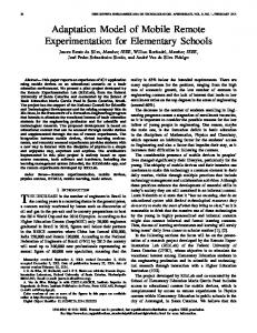
Fig. 1. The concept of the Home Automation system using the PDAbased Intelligent Robot System (HAuPIRS) architecture. The PDAbased mobile robot moves, manages, and controls home appliances, instead of human beings.
functions provided by the house. Microsoft has developed EasyLiving, which is focused on software functions, such as automatic person recognition [5]. Independent LifeStyle Assistant (ILSA) is designed to enable older adults as well as younger people with disabilities to live independently and safely at home [6]. These home automation systems are focused on constructing automatic home environments based on the Internet infrastructure. They assumed that there are some people to use them. By contrast, university labs focus on intelligence functions. Smart House Lab. at the University of Florida has built on the concepts of pervasive computing in order to assist older people with disabilities to live independently [7]. They use the smart phone as a universal interface at home. It has Matilda, which is robotic device and communicates with residents in the house. MARC (Medical Automation Research Center) at the University of Virginia has developed a communication module with a web-based data management server [1]. It analyzes the meal preparation patterns of people, including physiological signs such as heartbeat and body temperature. MavHome at the University of Texas in Arlington is for a home health monitoring system that will assist in daily basic activities [8]. MavHome sensors track vital signs, movement patterns, medicine taking schedules, and interaction with devices in the home. The Center for Future Health at the University of Rochester provides an emergency response service [9]. Aware Home at the Georgia Institute of Technology has focused on applications for supporting people with cognitive impairment in daily activities and communications [10]. Place Lab. of MIT has developed a portable kit that tracks movements of objects in the home,
0098 3063/09/$20.00 © 2009 IEEE
Authorized licensed use limited to: Sungkyunkwan University. Downloaded on February 25,2010 at 04:18:59 EST from IEEE Xplore. Restrictions apply.
IEEE Transactions on Consumer Electronics, Vol. 55, No. 3, AUGUST 2009
1488
such as furniture and kitchen tools [11]. Adaptive House at the University of Colorado focuses on designing a selfprogramming home system, based on the lifestyle, needs, and preferences of the residents [12]. Although they have numerous autonomous intelligence functions, it is difficult to add or change systems, such as cameras and automotive furniture, etc., which could increase the cost of building when the house is expanded. Numerous robotics institutes and universities are focusing on intelligent robot systems [13-20]. This makes it possible to reduce the cost of building home automation systems using the mobility of intelligent robot systems. But most of these mobile robot systems are not suitable for home environments. HERMES [13], at the Intelligent Robots Lab in University of Munich, is a humanoid robot system offering service to human beings. It has good mobility and high intelligence, but it is too heavy (250kg) and too tall (185cm) to use in a home environment. It uses two personal computers for operating all functions, and this leads to high costs (about $230 000). CareO-Bot, which is from the Swiss Fraunhafer, is a sliver-mate robot used to assist the movements of people [14]. It also uses personal computers for operating all functions and is too big to use for a home environment. PERSES [15], ISSAC [16], ETRO [17], SHR100 [18], MARY [19], and Guide Robot [20] are developed using personal computers or single board computers. These robots based on high performance platforms are only suitable for large buildings or specific purposes, such as in factories and museums, and are too unreliable to use in a home environment because of their great weight and size. There are also home robots of suitable size, such as ApriAlpha [21]. ApriAlpha is a communication robot between users and a home automation system based on speech recognition. It is a suitable robot in terms of the size, and specification. But it cannot monitor the home status, which is a necessary function of a smart home [1]. MostItech creates a home security and home automation robot which provides remote monitoring and controlling functions [22]. The problem with this robot is its lack of intelligence. It has the capability to move by remote controlling but it is unable to judge an emergency situation. It is useless if there are no human beings monitoring the system. Cleaning robots also have good specifications for a home environment, but they have no remote monitoring and controlling functions [23-25]. In this paper, we have designed the Home Automation system using the PDA-based Intelligent Robot System (HAuPIRS) architecture. HAuPIRS has an intelligent mobile robot system with remote monitoring and controlling functions for a home environment such as that shown in Fig. 1. HAuPIRS has overcome passiveness, which is the problem of the conventional home automation system, using the mobility of an intelligent mobile robot. HAuPIRS uses a PDA for the main operating system instead of a personal computer or single board computer in order to reduce the size and weight. We have developed simple algorithms for a PDA, as it has low performance and it is unable to use normal algorithms
which are implemented on personal computers. HAuPIRS has a home server system to manage and store the information about the home status. Users can monitor the home from the outside using the remote controlling and monitoring system, which is based on a 3D map. In Section II, we explain the Home Automation system using the PDA-based Intelligent Robot System (HAuPIRS) architecture. In Section III, we introduce the PDA-based Mobile Robot (PBMoRo) system. In Section IV, we present our experimental results. Finally, we conclude this paper in Section V.
II. HAUPIRS ARCHITECTURE We have designed the HAuPIRS Architecture. It consists of two parts; the residential gateway for home networking and the PDA-based mobile robot system. A. Home Network using the Residential Gateway Home networking is an essential condition for a home automation system [1]. It makes it possible to control and manage the home from anywhere. Fig. 2 shows the residential gateway for a home network. The residential gateway is connected with the internet and it is possible to connect with multi-devices, such as PCs, mobile phones, and PDAs, etc. Most home appliances and systems are connected in the residential gateway with wired or wireless networks. We can control and manage home appliances using this system, even from the outside. Fig. 2 is based on the assumption that most home appliances and systems are connected with the residential gateway. And this should consider which appliances and systems are used for a home before it is built. If there is any
Fig. 2. A residential gateway-based home networking system. It plays the role of a bridge to connect the home to an outside network and manage home appliances.
Fig. 3. A home network with a residential gateway using a mobile robot system. The HAuPIRS architecture provides mobility using a mobile robot and it provides visual information to users without any need for cameras in a home environment.
Authorized licensed use limited to: Sungkyunkwan University. Downloaded on February 25,2010 at 04:18:59 EST from IEEE Xplore. Restrictions apply.
H. S. Ahn et al.: PDA-Based Mobile Robot System with Remote Monitoring for Home Environment
disconnection in a home network, a home automation system is useless. If there is no camera, it just provides the status of the home appliances without visual information, which provides visual confirmation to users. The HAuPIRS architecture has a mobile robot system between the residential gateway and home appliances. Fig. 3 shows the residential gateway with a mobile robot system. Home appliances are connected with the residential gateway, and a mobile robot is used when there is disconnection of a home network and users want to check the home status using visual information. B. Home Automation system using PDA-based Intelligent Robot System (HAuPIRS) Architecture The Home Automation system using the PDA-based Intelligent Robot System (HAuPIRS) architecture is shown in Fig. 4. It can be divided into three layers; the user layer, the manager layer, and the action layer. The user layer is for the user interface including remote and local control. The user can monitor a home with the status information from the residential gateway and the visual information from a mobile robot. Especially, it is possible to connect with multi-devices, such as PCs, mobile phones, PDAs, etc. The manager layer is for managing the home status, and consists of three parts; a server part, a home appliances part, and a storage part. The server system is the residential gateway, and connects with multi-devices in the user layer. It manages most of the information of the home, analyzes the home status information, and sends it to the remote monitoring system. If visual information is needed or the home network is disconnected, the server system commands the robot system to move and control the home appliances, and gets visual information from the camera of the mobile robot, as shown in Fig. 5. The home appliances part controls all appliances, and the storage system stores all the status information of the house. The action layer has a robot system which is a PDA-based platform and has two intelligent functions; a SLAM engine and a vision processing engine. The robot system always connects with the server system and shares all information. The robot actuator is for physical processes, such as controlling the motor, camera, sensors, etc. It gets commands from the intelligent functional engine, and sends new information to the server system. It has its own controller and algorithms to achieve the jobs. The HAuPIRS architecture uses a PDA instead of personal computers or single board computers as a main system. As this leads to a reduction in the power consumption of the robot system, it uses a small battery instead of a heavy lead battery. Consequently, the robot system becomes smaller and lighter, and this leads to an increase in its driving time. It is a suitable size for a home environment and a low cost robot system. On the other hand, a PDA has lower performance and insufficient memory. To deal with lower performance, the HAuPIRS architecture needs simple algorithms for SLAM and vision processing, and it uses the residential gateway to store
1489
information for dealing with insufficient memory. The HAuPIRS architecture is efficient in case of upgrading a home automation system. It is difficult to upgrade after building of conventional systems is completed. If a house is expanded, the cost is increased, because more cameras and sensors are needed. On the other hand, the HAuPIRS architecture has a robot system with cameras and various sensors, and it has the capability to get information of the house by moving around. Consequently, as no additional hardware such as cameras is needed, it is possible to reduce the cost and time for building. Moreover, there is no blind spot, because the robot has a pan-tile camera system. Users control the robot and the pan-tilt camera, and HAuPIRS provides visual information without a blind spot. If there is a trespasser, the robot records the trespasser using visual information, by following him/her.
PC based Monitoring System Control UI
PDA based Monitoring System
3D Map
2D Map
User Layer
Server System Communication Threading Pool
Home Appliances
Packet Relay
Home Control
Information Data Mining
Electrical Fan
Storage Communication Module
Lamp TV
Manager Layer
Robot System
...
Communication Module Intelligent Functional Engine S L A M
Obstacle Avoidance Navigation Motion Generation
V I S I O N
Face Recognition Object Detection Landmark Detection
Robot Actuator
Action Layer
Fig. 4. Home Automation system using the PDA-based Intelligent Robot System (HAuPIRS) architecture. It consists of three layers; the user layer, the manager layer, and the action layer. A lower layer is closer to the actual physical mechanics, motors and sensors, than an upper layer.
Fig. 5. A common scenario of robot movement in home network and home automation environment. The robot controls home appliances and navigates according to a user’s needs. Whenever the robot is operating, it communicates with the residential gateway via a wireless network.
Authorized licensed use limited to: Sungkyunkwan University. Downloaded on February 25,2010 at 04:18:59 EST from IEEE Xplore. Restrictions apply.
IEEE Transactions on Consumer Electronics, Vol. 55, No. 3, AUGUST 2009
1490
III. PBMORO SYSTEM We have developed a system which is based on the HAuPIRS architecture. We call this system the PBMoRo system (PDA-based Mobile Robot System). Fig. 6 shows the PBMoRo system architecture. It consists of two parts; the mobile robot system, and the server system. The mobile robot
system uses a PDA for the main computing system, and has a motion controller board to move around and a CF (Compact Flash) camera to get visual information. The PDA-based mobile robot has various sensors and patrols a home using security functions. It connects to the server system via wireless internet. As it uses a PDA with low computational capability, simple algorithms are required. The server system plays the role of the residential gateway and manages all information of the home. It provides a remote monitoring system for users outside of the home. It is also possible to connect with multi-mobile devices such as PDAs, mobile phones and PCs via the internet. A. Robot System Fig. 7 shows the PDA-based mobile robot system. It has a suitable size (300 x 400 x 300 mm (w x d x h)) and weight (8 kg) for a home environment. The body is made of aluminum and acryl. The actuator and the pan-tilt system have two motors each. It has a CF camera, which has 1.3 mega-pixels and processes 30 frames/sec, five ultrasonic sensors, a CO2 sensor, and a VOC (Volatile Organic Compounds) sensor. It uses two 15 V Li-ion batteries. In the robot system, the most important issue is to calculate accurate current coordinates of the robot, as the system should be synchronized with the remote monitoring system. The motion generator uses a position control method, and we can get the current coordinates of the robot as follows. θGR , the angle between the robot, and the goal position, is formulated as follows:
θG − θR = θGR ,
(1)
where θG is the angle between the position of the goal and the origin, and θR is the angle between the robot and the origin. The moving distance per sampling time is calculated using the motor encoder information, and we can get the velocity of both wheels of the robot. VL , the velocity of the left wheel, and VR , the velocity of the right wheel, are expressed as: Fig. 6. PBMoRo System Architecture. It consists of two parts; the mobile robot system, and the server system.
VL = δL , T VR = δR , T
(2) (3)
where δL is the moving distance of the left wheel per sampling time, δR is the moving distance of the right wheel per sampling time, and T is the sampling time. moving angle per sampling time, is given by: Fig. 7. PDA-based mobile robot system. The left-hand robot has no shell and the right-hand robot has a shell which is designed to be human friendly. It prevents injuries to users and damage to the robot system.
δθ
−δL , δθ = δRω
Authorized licensed use limited to: Sungkyunkwan University. Downloaded on February 25,2010 at 04:18:59 EST from IEEE Xplore. Restrictions apply.
, the
(4)
H. S. Ahn et al.: PDA-Based Mobile Robot System with Remote Monitoring for Home Environment
where ω is the width of the robot. Using (2), (3), and (4), VC , the linear velocity of the robot, and Vω , the angular velocity of the robot, are calculated as follows:.
VC = VR+VL = δR+δL , 2 2T
(5)
Vω = δθ = δR −δL , T T ⋅ω
(6)
Using equations (4)-(6), we can get the current coordinates of the robot. OX (k + 1) , the current coordinate x, OY (k + 1) , the current coordinate y, and Oθ (k + 1) , the current angle of the robot, are determined as follows:
OX (k + 1) = OX (k ) + δR +δL ⋅ cos(Oθ (k )) , 2 δ R +δL OY (k + 1) = OY (k ) + ⋅ sin (Oθ (k )) , 2 ω
(7)
(8)
Oθ (k + 1) = ω Oθ (k ) + δθ ,
(9)
1491
[26]. But as a PDA has lower performance than a computer, it should use simple algorithms. The PDA system controls the actuator part of the robot system, and uses three threads; image processing, serial communication, and wireless communication. Fig. 8 shows the flow chart of the PDA system. If the robot cannot detect obstacles and fails to update the map for path planning with a given goal position, it collides with obstacles and this results in the slip problem. To solve this problem, the robot system should have simple obstacle avoidance and map updating functions for the PDA environment. Fig. 9 shows the site plan of the robot’s five ultrasonic sensors and divides the circumference into four sections. Fig. 10 shows the flow chart of the map updating system. The PDA system updates the map using sensor data, and the position of a detected obstacle is calculated as follows:
XO = XR + α [ n ] ⋅ cos⎛⎜θR + θ [ n ] ⎞⎟ , ⎠ ⎝ YO = YR + α [ n ] ⋅ sin ⎛⎜θR + θ [ n ] ⎞⎟ , ⎝ ⎠
(10) (11)
B. PDA System The biggest difference between a computer-based robot and a PDA-based robot is the processing performance. A PDA is 10x cheaper than a computer and consumes 30x less power System ON
Input Vision Data With Camera
Vision Preview
OFF
Input Robot Control With PDA
Input Robot Control With Server
Get Control Data
Wireless Comm
ON
Vision Display
Vision Data Trans with UDP
Fig. 9. The site plan of the robot’s five ultrasonic sensors. It divides the circumference into four sections.
ON
Vision Thread Get Vision Data
OFF
TCP Thread Process Control Robot
Get Control Data
Send Control Data
Control Data Trans with TCP
Serial Comm
OFF
ON Serial Thread Control Robot
System OFF
Fig. 8. The flow chart of the PDA system. It consists of three parts; the image processing part, the robot control part, and the wireless communication part. Each part uses a thread and influences the others.
Fig. 10. The flow chart of the map updating system. This is a simple algorithm compared with map building algorithms in order to reduce the processing load.
Authorized licensed use limited to: Sungkyunkwan University. Downloaded on February 25,2010 at 04:18:59 EST from IEEE Xplore. Restrictions apply.
IEEE Transactions on Consumer Electronics, Vol. 55, No. 3, AUGUST 2009
1492
where θ[n] is the setting angle of each of the ultrasonic sensors which are; -90°, -45°, 0°, 45°, 90°, and α [n ] is the sensing distance of each of the sensors, and θR is the angle of the robot. The PDA system makes the temporal goal position to avoid the detected obstacles, instead of recalculating the path of the robot to the goal position, in order to reduce the processing load. C. Server System and Remote Monitoring System The server system is important, since it plays the role of a bridge between the robot system and the remote monitoring system. Consequently, data transition is the core process of the server system, and Fig. 11 shows the diagram of the data flow in the server system, which is based on the HAuPIRS architecture. The PBMoRo system has two kinds of remote monitoring system; the PDA-based system (left-hand figure of Fig. 12), and the PC-based system (right-hand figure of Fig. 12 and Fig. 13). Users connect to the remote monitoring system via the login process for security (right-hand figure of Fig. 12). The PC-based remote monitoring system shows streaming images from the camera of the actual robot (righthand side of Fig. 13). It also shows the 3D map, which is synchronized with the actual robot. For drawing 3D maps, we have developed the map editor (Fig. 14). The remote monitoring system shows streaming images from the camera of the robot, and it is possible to control the pan-tile system. If the goal position is given, the robot moves autonomously, and users can verify that the robot is moving correctly. It is also possible to check the status of the home using visual information.
Fig. 13. The remote monitoring system. It provides a 3D map of the home and visual information from the robot’s camera.
Fig. 14. The 3D map editor. It is easy to draw the basic map of the house and it can be used in the remote monitoring system.
(a)
Fig. 11. The diagram of the data flow in the server system which is based on the HAuPIRS architecture.
(b) Fig. 12. The remote monitoring systems. The left-hand figure is the PDA-based system and the right-hand one is the login process of the PC based system.
Fig. 15. The experimental results of the motion generator. Figure (a) shows the path of the robot. The top figure of (b) is the linear velocity of the robot. The bottom figure of (b) is the angular velocity of the robot.
Authorized licensed use limited to: Sungkyunkwan University. Downloaded on February 25,2010 at 04:18:59 EST from IEEE Xplore. Restrictions apply.
H. S. Ahn et al.: PDA-Based Mobile Robot System with Remote Monitoring for Home Environment
IV. EXPERIMENTS
A. Robot Simulator We developed a robot simulator for testing our algorithms in the PDA environment. Fig. 15 shows the experimental results of the motion generator. It made the linear velocity and the angular velocity of the robot. Fig. 15 shows: (a) the path of robot calculated by the linear velocity, and (b) the angular velocity. We used the same method for the actual robot system, and verified that the data of the robot simulator was useful for this system. Fig. 16 shows the experimental results of obstacle avoidance and map updating in the robot simulator. This has five distance measurement sensors at the same position as the actual robot system. The robot simulator calculated the path to the goal position. If obstacles were detected by the sensors, it made the temporal goal position on the calculated path. After the robot reached the temporal goal position, it used the first calculated path. We used the same algorithms for the actual robot system.
1493
When the user set the goal position, the remote monitoring system sent the goal position to the robot system via the server system. Then the robot system calculated the path and the motion generator calculated the linear and angular velocity of the robot. The robot system sent the velocity and position information back to the remote monitoring system via the server system. In this process, it used the home appliances position as the landmarks, which were pre-decided, and the remote monitoring system compensated for the position of the robot. We verified that synchronization was achieved via this experiment.
(a)
(b)
(c)
(d)
Fig. 17. The experimental results about synchronization between the robot system and the PC based remote monitoring system. (a), (b), (d) The left-hand figure is the actual robot, and the right-hand one is the 3D remote monitoring system. (c) The right-hand part shows the streaming image from the actual robot.
Fig. 16. The experimental results of obstacle avoidance and map updating. It uses the same algorithms for the actual robot system. This includes the sensing information, the robot position, the goal position, and the velocity of the robot, etc.
B. Synchronization with Remote Monitoring System When using these monitoring systems, synchronization between the actual and virtual circumstances is the most important issue. We have devised synchronization experiments, and Fig. 17 shows the experimental results of synchronization between the robot system and the PC-based remote monitoring system. Fig. 17 (a), (b), and (d) shows the synchronization process (the left-hand figure is the actual robot, and the right-hand one is the 3D remote monitoring system). Fig. 17 (c) shows the image streaming process in the 3D remote monitoring system.
C. Obstacle Avoidance and Map Updating The PBMoRo system does not recalculate the path while moving in order to reduce the processing load. But if there are obstacles in the path or near the robot, an obstacle avoidance function is needed, as it is impossible to use the calculated path. We devised an experiment on obstacle avoidance and map updating, and Fig. 18 shows the experimental results. When the robot detected obstacles while moving along the calculated path (Fig. 18 (a)), it made the temporal goal position nearby the first calculated path. After arriving at the temporal goal position, it checked for the possibility of returning to the first calculated path, as shown in Fig. 18 (b). If this was possible, the robot returned to the first calculated path and moved to the goal position along the path (Fig. 18 (c)); otherwise the robot made the second temporal goal position nearby the first calculated path, and repeated this process until arriving at the final goal position. While the robot avoided obstacles, the map was also updated, as shown in Fig. 18 (d). In this process, it used the sensing data from the five ultrasonic sensors and sent the information obtained to the server system. The server system built a new map by this means, and this reduced the processing load. We verified that obstacle avoidance and the map updating
Authorized licensed use limited to: Sungkyunkwan University. Downloaded on February 25,2010 at 04:18:59 EST from IEEE Xplore. Restrictions apply.
IEEE Transactions on Consumer Electronics, Vol. 55, No. 3, AUGUST 2009
1494
(a)
appliances, as shown in Fig. 19 (c), (f), and (i), and sent streaming images to the monitoring system via the server system. We could ascertain the status of the home appliances via the monitoring system. Based on these experiments, we verified the performance of the HAuPIRS architecture in the home environment, and verified that the proposed architecture overcomes the limitations of conventional home automation systems.
(b)
(c)
(d)
Fig. 18. The experimental results of obstacle avoidance and map updating. (d) The result of updating the robot’s map.
function were effectively executed using the proposed simple algorithms. D. Home Appliances Control The PBMoRo system controls and manages home appliances using wireless communication. To get visual information, the robot system moves nearby home appliances and provides streaming images to users. We devised an experiment on this process, and Fig. 20 shows the experimental results. We used three home appliances: a fan (Fig. 19 (a) ~ (c)), a lamp (Fig. 19 (d) ~ (f)), and a TV (Fig. 19 (g) ~ (i)). When the user issued a command to turn on the home appliances on the remote monitoring system, it sent the command to the server system. When the home appliances were turned on, the server system sent a message with the status. When they were turned off, the server system ordered the robot system to move nearby them,, as shown in Fig. 19 (b), (e), and (h). The robot system controlled the home
(a)
(b)
(c)
(d)
(e)
(f)
(g)
(h)
(i)
Fig. 19. The experimental results of home appliances control. The top row shows controlling the fan. The middle row shows controlling the lamp. The bottom row shows controlling the TV.
V. CONCLUSIONS As conventional home automation systems build automatic environments using networks, the cost of expanding the new functions is high. A conventional intelligent robot system is unsuitable for a home environment, because it is heavy and expensive. To solve these problems, we have designed the Home Automation system using the PDA-based Intelligent Robot System (HAuPIRS) architecture. The HAuPIRS architecture uses the PDA-based mobile robot system for the home automation system. It ensures that there is no additional cost even though the house is expanded, using a mobile robot which has cameras and various sensors. As the HAuPIRS architecture uses a PDA for the main processing system, simple algorithms are needed. A PDA is small, light, and has a long driving time, but lower performance compared to the single board computer, which is usually used in intelligent service robots. As a consequence, we have developed simple algorithms suitable for the performance of a PDA. Moreover, as a PDA has a small storage space, the HAuPIRS architecture has a residential gateway, which is the server system between the robot system and the outer network system. All information and commands are transferred through this server system. We have developed the PBMoRo system (PDA-based Mobile Robot System). It has two parts; the robot system, and the server system with the remote monitoring system. The robot system has a motion generator using simple calculation to control the two wheels, and a pan-tilt system. We also have developed two remote monitoring systems; a PC-based system, and a PDA-based system. Especially, the PC-based system is 3D environment to enable easy understanding of the home status. We have easily built maps for the PC-based system using the map editor. We have tested the motion generator using the robot simulator, and used it for the actual robot. Users have sent commands to the robot system via the server system using the remote monitoring systems, and the robot moves to the goal position with synchronization. The robot has updated the map as well as avoided obstacles at the same time. The PBMoRo system has managed and controlled three home appliances with streaming camera images. These experiments have verified the performance of the proposed system.. In the future, we will develop more intelligent algorithms for the PDA environment.
Authorized licensed use limited to: Sungkyunkwan University. Downloaded on February 25,2010 at 04:18:59 EST from IEEE Xplore. Restrictions apply.
H. S. Ahn et al.: PDA-Based Mobile Robot System with Remote Monitoring for Home Environment
ACKNOWLEDGMENT
This research work has been supported by the Korean Ministry of Knowledge Economy, the BK21 program, the ASRI, and the Engineering Research Institute, Perception and Intelligence Laboratory, PIRC at Seoul National University.
REFERENCES [1] [2] [3] [4] [5] [6]
[7]
[8] [9] [10]
[11] [12] [13] [14] [15]
[16]
[17]
[18]
William, C. Mann, and Bradley, R. Milton, “Home automation and smart homes to support independence,” Smart technology for aging, disability, and independence, Wiley Interscience, pp. 33-66, 2005. Lawson, S., “IBM Builds a smart house,” PC World, 2004. http://www.e2home.com/new_main.asp Berlo, A., “Home networking and home automation for older people,” In the Proceedings of the International Conference on Aging, Disability and Independence, pp. 158, 2003. http://research.microsoft.com/easyliving Kiff, L., Krichbaum, K., Miller, C., and Wu, P., “Design philosophies applied in an elder home monitoring system,” In the Proceedings of the International Conference on Aging, Disability and Independence, pp. 143-145, 2003. Davenport, R., Helal, S., Mann, W., and Zabadani, H., “Assistive environments for elder care-integrating smart phones with smart homes,” In the Proceedings of the International Conference on Aging, Disability and Independence, pp. 128-129, 2003. Cook, D., Das, S., Gopalratnam, K., and Roy, A., “Health monitoring in an agent-based smart home,” In the Proceedings of the International Conference on Aging, Disability and Independence, pp. 154-155, 2003. Pentland, A., and Fauchet, P., “Personal health systems for the future,” In the Proceedings of the International Conference on Aging, Disability and Independence, pp. 176-177, 2003. Abowd, G., Bobick, A., Essa, I., Fisk, D., Mynatt, B., and Rogers, W., “Aware home for aging in place,” In the Proceedings of the International Conference on Aging, Disability and Independence, pp. 122-123, 2003. Intille, S., and Larson, K., “Designing and evaluating technology for independent aging in the home,” In the Proceedings of the International Conference on Aging, Disability and Independence, pp. 146-147, 2003. Mozer, M. C., “The adaptive house,” University of Colorado Department of Computer Science, 2004. Bischoff, R., and Graefe, V., “HERMES - a versatile personal robotic assistant,” Proceedings of the IEEE, vol. 92, pp. 1759-1779, 2004. Lenser, S., and Veloso, M., “Sensor resetting localization for poorly modeled mobile robots,” In the Proceedings of the International Conference on Robotics and Automation (ICRA), pp. 1225–1232, 2000. Gross, H.-M., Boehme, H.-J., and Wilhelm T., “Contribution to visionbased localization, tracking and navigation methods for an interactive mobile service-robot,” In the Proceedings of the IEEE International Conference on Systems, Man, and Cybernetics, pp. 672–677, 2001. Dong To Nguyen, Sang-Rok Oh, and Bum-Jae You, “A framework for Internet-based interaction of humans, robots, and responsive environments using agent technology,” IEEE Transactions on Industrial Electronics, vol. 52, Issue 6, pp. 1521-1529, 2005. Jeonghye Han, Jaeyeon Lee, and Youngjo Cho, “Evolutionary role model and basic emotions of service robots originated from computers,” In the Proceedings of the IEEE International Workshop on Robot and Human Interactive Communication (ROMAN), pp. 30-35, 2005. Moonzoo Kim, Kyo Chul Kang, and Hyoungki Lee, “Formal Verification of Robot Movements - a Case Study on Home Service Robot SHR100,” In the Proceedings of the IEEE International Conference on Robotics and Automation (ICRA), pp. 4739-4744, 2005.
1495
[19] Taipalus, T., and Kazuhiro K., “Development of service robot for fetching objects in home environment,” In the Proceedings of the IEEE International Symposium on Computational Intelligence in Robotics and Automation (CIRA), pp. 451-456, 2005. [20] Yoshikazu K., Takayuki K., Yasuyuki S., Kiyoshi K., and Hiroshi I., “An Approach to Integrating an Interactive Guide Robot with Ubiquitous Sensors,” In the Proceedings of the IEEE/RSJ International Conference on Intelligent Robots and Systems (IROS), pp. 2500-2505, 2004. [21] Yoshimi T. et. al., “Development of a concept model of a robotic information home appliance, ApriAlpha,” In the Proceedings of the IEEE/RSJ International Conference on Intelligent Robots and Systems (IROS), pp. 205-211, 2004. [22] MostItech, http:// www.mostitech.com [23] http://store.irobot.com/shop/index.jsp?categoryId=280460 [24] http://www.iclebo.com [25] http://trilobite.electrolux.com [26] Ho Seok Ahn, and Jin Young Choi, “Home Automation System using Intelligent Mobile Robot in Ubiquitous,” In the Proceedings of the International Conference on Ubiquitous Robots and Ambient Intelligence, pp. 6-11, 2005.
Ho Seok Ahn received his B.S. degree in Information and Communication Engineering from Sungkyunkwan University in 2005. He was a visiting researcher at the Intelligent Systems Research Institute at AIST in 2006. He is currently a Ph.D. candidate student at the School of Electrical Engineering and Computer science at Seoul National University, Korea, since 2005. He is a researcher of the Perception and Intelligence Research Center. His research interests include intelligent service robots, artificial emotional systems, modular robot systems, and visual surveillance. In-Kyu Sa received both his B.S. degree in Information and Communication Engineering, and his B.S. degree in physics from Sungkyunkwan University in 2003. He received his M.S. degree in Electrical Engineering from Sungkyunkwan University in 2006. He is currently a senior researcher at Samsung Electronics Co. His research interests include intelligent service robots, cognitive navigation, path planning and localization. Jin Young Choi received his B.S., M.S., and Ph.D. degrees in Electrical Engineering and Computer Science from Seoul National University in 1982, 1984, 1993, respectively. He was a researcher at the Electronics and Telecommunications Research Institute (ETRI) from 1984 to 1994. He was a visiting professor at the University of California, Riverside from 1998 to 1999. He is currently a professor at the School of Electrical Engineering and Computer science at Seoul National University, Korea. He is a director of the Perception and Intelligence Research Center. His research interests include visual surveillance, intelligent systems, and adaptive control.
Authorized licensed use limited to: Sungkyunkwan University. Downloaded on February 25,2010 at 04:18:59 EST from IEEE Xplore. Restrictions apply.