Many Integrated Core (MIC) architecture.3. For example ..... with a roaming data pointer (RDP) struc- ture. ... similar to Intel's MIC architecture,3 a. 32-core ...
[3B2-14]
mmi2010060025.3d
8/12/010
15:51
Page 25
..........................................................................................................................................................................................................................
PERFORMANCE AND ENERGY IMPLICATIONS OF MANY-CORE CACHES FOR THROUGHPUT COMPUTING ..........................................................................................................................................................................................................................
PROCESSORS THAT TARGET THROUGHPUT COMPUTING OFTEN HAVE MANY CORES, WHICH STRESSES THE CACHE HIERARCHY. LOGICALLY CENTRALIZED, SHARED DATA STORAGE IS NEEDED FOR MANY-CORE CHIPS TO PROVIDE HIGH CACHE THROUGHPUT FOR HEAVILY READ-WRITE SHARED LINES. TECHNIQUES TO REDUCE ON-DIE AND OFF-DIE TRAFFIC HAVE A DRAMATIC ENERGY BENEFIT FOR MANY-CORE CHIPS.
......
Throughput computing,1 which is also referred to as general-purpose computing on graphics processing units (GPGPU) computing, is gaining prominence. Consequently, architects are beginning to examine how to best design systems for throughput computing applications. These applications span many domains and are already critical on a variety of platforms from highperformance computing (HPC) machines to client machines. They involve performing a huge number of calculations with a large amount of parallelism. This makes them a natural fit for processors with many cores, such as NVIDIA’s Fermi2 and Intel’s Many Integrated Core (MIC) architecture.3 For example, scientific computing applications, such as computational fluid dynamics, seismic processing, and molecular dynamics increasingly use GPUs. Nonscientific domains such as financial analytics, computer vision, and image processing and recognition also use GPUs. A chip with many processor cores has enormous peak arithmetic capabilities, but using those capabilities effectively is difficult.
To keep the many cores busy, the memory system must feed and facilitate communication between the cores efficiently. The cache hierarchy is perhaps the most critical component of many-core memory systems. It hides the latency of the rest of the memory system, provides fast core-to-core communication, and provides sufficient bandwidth to keep the cores busy. Although GPUs have traditionally eschewed a CPU-like cache hierarchy, this seems to be changing as they increase their focus on throughput computing. A recent study shows the value of caches for throughput computing.4 Also, NVIDIA’s Fermi incorporates a 64-Kbyte private cache per streaming multiprocessor and a 768-Kbyte shared cache. In this work, we study cache design for throughput computing by considering both power and performance. The most closely related work is on cache design for generalpurpose multicore processors.5-7 We leverage that work, but face two new challenges. First, because we focus on throughput computing, we consider significantly more cores. This stresses the intercore communication
Christopher J. Hughes Changkyu Kim Yen-Kuang Chen Intel Labs
...................................................................
�
0272-1732/10/$26.00 c 2010 IEEE
Published by the IEEE Computer Society
25
[3B2-14]
mmi2010060025.3d
8/12/010
15:51
Page 26
............................................................................................................................................................................................... THROUGHPUT COMPUTING
Table 1. Splash-2 benchmark summary.
Benchmark
Working set size
Cache miss
Prefetch
(Kbytes)
rate (%)
coverage (%)
Input
barnes
16,384 particles
64
1.2
0
cholesky
tk29.0 problem
128
1.1
50
fft
262,144 points
256
5.0
33
ocean
258 � 258 grid
512
4.4
59
radiosity
room model
128
0.6
16
radix
1 million keys
256
4.2
30
water-spatial
512 molecules
64
0.2
4
Table 2. Throughput computing kernels summary.
Benchmark binomial
Option pricing with 1D binomial tree
gauss
Working
Miss
Prefetch
set size
rate (%)
coverage (%)
128 Kbytes
10.0
64
512 � 512 grid
64 Kbytes
6.5
87
Description
Solves boundary value
Input 256 options, 1,024 time steps
problem with red-black Gauss-Seidel kmeans
Clusters data using
17,695 points, 20 dims,
2 Mbytes
0.7
64
mmm
K-means algorithm Multiplies two dense
21 clusters 1,024 � 1,024 matrices
256 Kbytes
3.7
0
640 � 480 video, three
256 Kbytes
3.7
52
70 � 45 � 55 grid
2 Mbytes
5.4
63
512 � 1,024 matrix
128 Kbytes
30.0
83
Detects faces in image using
256 � 256 image, 24 � 24
2 Mbytes
4.2
91
support vector machine
blocks, 500 vectors
matrices objectdetect
Detects objects in video using boosted cascade of Haar features
pcg
Solves for fluid velocities in a
scales, three stages, 793 features
3D grid using precondisvd
tioned conjugate gradient Performs singular value decomposition with one-sided Jacobi method
svm
mechanism. Second, throughput computing applications are often latency tolerant. Thus, designs that minimize average access latency might not give the best performance.
Throughput applications We use throughput computing kernels formulated from recently proposed benchmark suites8,9 and traditional HPC workloads from Splash-2 scientific benchmarks.10 Tables 1 and 2 summarize our benchmarks and include some memory characteristics for 64thread runs. We determine the second-level
....................................................................
26
IEEE MICRO
per-thread working set size (the working set just beyond the first-level [L1] cache) by measuring miss rate for private caches of various sizes and finding the knee in the curve. For good parallel scalability, the working set should fit in cache. Thus, for benchmarks that use cache tiling, we set the tile size as 256 Kbytes (we model 256 Kbytes of second-level [L2] cache per core). The working set sizes range from 64 Kbytes to 2 Mbytes, which suggests that an L2 cache that is smaller than 2 Mbytes might give bad performance for some benchmarks.
[3B2-14]
mmi2010060025.3d
8/12/010
15:51
Page 27
80 60 40
1
2−7 R
8−63 R
64 R
2−7 RW
8−63 RW
svm
svd
pcg
objectdetect
mmm
kmeans
gauss
binomial
water
radix
radiosity
ocean
cholesky
fft
20 barnes
Lines/accesses (%)
100
64 RW
Figure 1. Data sharing characteristics. Percentage of L2 cache lines (left bar for each benchmark) and L2 cache accesses to data (right bar for each benchmark) shared by the given number of cores. (R ¼ read sharing; RW ¼ read-write sharing)
The cache miss rate column shows the miss rate for a 64-thread run in which each thread has a 32-Kbyte private cache and no prefetching. The miss rate is another measure of the importance of the rest of the cache hierarchy. Many of the benchmarks have significant miss rates, indicating that they will frequently access the L2 cache. Thus, their performance and/or energy might be sensitive to the behavior of the L2 cache and lower levels of the memory hierarchy. The prefetch coverage column gives some insight into memory access patterns. This is the percentage reduction in L1 misses when we add an L1 stride prefetcher to the system used to measure the miss rate. Most of the benchmarks see large reductions in misses (30 percent or more), indicating that they have strong streaming patterns. Figure 1 shows the degree of sharing for each benchmark’s data accesses. The data is from a simulated 64-thread run with private 32-Kbyte L1 caches and a shared L2 cache. The sharing degree for a cache line is the number of cores that access that line at the L2 cache within a window of 32 K L2 accesses. We show sharing degree in both the spatial and frequency domains. That is, the left bar for each benchmark shows the fraction of lines touched that have each sharing degree (spatial), and the right bar shows the fraction of accesses to lines with each
sharing degree (frequency). We also separate out read sharing (R) from read-write sharing (RW). A line is read-write shared if it is accessed by multiple cores and at least one of the accesses is a write. In the spatial domain, many of the benchmarks have significant fractions of shared data—nine out of 15 benchmarks have more than 10 percent shared lines—but most data is private for all except svm. In the frequency domain, shared data is far more prevalent. Also, we notice an important phenomenon: for some benchmarks, a very small set of heavily read-write shared lines accounts for a large fraction of accesses (the black portion of the bars). For example, in pcg, 0.1 percent of the lines are involved in global read-write sharing, but these lines account for 19 percent of L2 cache accesses. These lines are related to synchronization and dynamic task scheduling and, therefore, accesses to them are often on the benchmark’s critical path.
Cache designs We evaluate a range of data cache designs for throughput computing. Because the design space for caches is so large, we constrain the problem in the following ways. First, we assume two levels of caching: a private, L1 cache for each core, and a last-level cache (LLC), whose design will vary. We enforce
....................................................................
NOVEMBER/DECEMBER 2010
27
[3B2-14]
mmi2010060025.3d
8/12/010
15:51
Page 28
............................................................................................................................................................................................... THROUGHPUT COMPUTING
Core + L1
Private LLC Tag
Data Switch
Tag directory Tag (a)
Dir
Core + L1
Core + L1
Switch
Switch RDP
LLC partition
Shared LLC partition
Tag Ptr Tag Dir
Data
(b)
Tag
Dir
Data
(c)
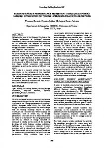
Figure 2. Tile designs with three last-level cache (LLC) designs: a private LLC (a), a flexible LLC that prohibits replication (b), and a shared LLC (c). (RDP ¼ roaming data pointer)
inclusion between the L1 cache and the LLC. Our findings are generally applicable to any hierarchy with one or more levels of private cache backed by an LLC. Second, we assume support for directory-based hardware cache coherence between the private caches. Third, we assume the processor has a tiled design, as shown in Figure 2. Each tile has a core plus L1 cache, a partition of the chip’s LLC, and a partition of the chip’s directory. We can define a spectrum of cache designs based on a key design criterion— flexibility regarding where a given line can reside in the LLC. For all designs we consider, any and all of the L1 caches might hold a given cache line (simultaneously, if clean). However, depending on the LLC design, only a (specific) subset of the tiles’ LLCs can hold a given line. A very flexible design permits all tiles to hold it while a very inflexible design permits only a single, specific tile to hold it. Flexibility is a key criterion because it impacts both performance and energy consumption. It affects the distance an LLC request and reply must travel through the on-die network. Access latency and ondie bandwidth usage might be lower for more flexible designs because data might be closer to a requesting core. Off-die bandwidth usage might be lower for less flexible designs because they allow fewer copies of a
....................................................................
28
IEEE MICRO
line to coexist on the chip. Thus, they have higher effective cache capacity.
Private Our private LLC design attempts to minimize LLC latency and energy by holding a core’s data as close to it as possible. The LLC in a core’s tile serves all misses from the core’s L1 cache. When a core accesses a line, it is brought into that tile’s LLC; that is, replicas of a read-shared line can co-exist in all LLC tiles simultaneously. This design can hold fewer unique cache lines than a less flexible design that limits replication, which can lead to more LLC misses. Figure 2a shows a tile using a private LLC. In addition to a core, L1 cache, and private LLC, each tile contains a tag directory. Each cache line is mapped via an address hashing function to a specific tile, called its home tile. The tag directory in the home tile maintains coherence for the line between the private LLCs. A tag directory holds an entry for each line in the aggregate LLC that maps to it. The entry contains a tag and directory state information. When an access misses in an LLC, the LLC sends a request to the home tag directory to see if the line is anywhere else on chip. If it is, the directory services the request with a cacheto-cache transfer regardless of whether the line is clean or dirty.
[3B2-14]
mmi2010060025.3d
8/12/010
15:51
Uncontrolled replication Our uncontrolled replication LLC design is similar to the private design, but it attempts to increase the number of unique lines held in the aggregate LLC. It allows unlimited replication of lines, but gives unique lines a chance to stay on chip if they are evicted. When a tile’s LLC evicts a line with only one sharer, it migrates the line to the home tile’s LLC unless the line is already at its home tile, in which case it is evicted from the chip. Uncontrolled replication uses the same physical design as a private LLC. It differs only in how it handles LLC evictions. When an LLC evicts a line, it notifies the tag directory. If this is the only copy of the line on the chip, the tag directory migrates the line to the LLC in the home tile. Uncontrolled replication was inspired by victim migration.7
Controlled replication Our controlled replication LLC design builds on the uncontrolled replication design and attempts to further increase the number of unique lines held in the aggregate LLC. It allows replication but deprioritizes certain replicas via the replacement policy. It attempts to detect when a private LLC is too small to hold a core’s working set. The design makes replicas that are part of such a working set next in line for replacement. Controlled replication uses the same physical design as a private LLC and includes the migration policy of uncontrolled replication. It augments each LLC line with a bit that indicates whether the line was reused after being inserted into the cache. A reused line is likely part of a working set that fits in a private LLC. When a line is evicted, the reuse bit is sent to the tag directory, which stores the bit with the directory information. When the tag directory initiates a clean cache-to-cache transfer (when a replica is created), it sends the reuse bit to the requester. If the reuse bit is not set, the LLC inserts the line into the least recently used (LRU) way to limit the space that replicas with no temporal locality can occupy. Controlled replication was inspired by cooperative caching.5
No replication Our no replication LLC design further limits flexibility by completely eliminating
Page 29
replication. That is, no replication allows a cache line to reside in at most one tile’s LLC at a time. No replication attempts to place private lines (those accessed by one core at a time) in the accessing core’s tile. It attempts to place shared lines in logically centralized storage (the lines’ home tiles) to make them easy to find and to prevent ping-ponging between tiles. Figure 2b shows a tile using no replication. The design holds shared lines in the home tile’s LLC, whereas it might place private lines in any tile’s LLC. Each LLC entry in this design includes not only tag and data, but also directory information so that the LLC can maintain coherence between L1 caches for shared lines. Thus, the LLC controller is also a directory controller. The design tracks private lines with a roaming data pointer (RDP) structure. The RDP in a line’s home tile will hold an entry with the tag and tile ID (pointer to the line). By default, lines are kept in their home LLC. However, if a line is only in use by one core and is reused by that core, the home LLC migrates the line to the requester’s LLC. When the home migrates a line, it deallocates its entry in the home LLC and allocates an entry in the RDP to record the line’s location. To exploit data migration, L1 misses check their local LLC before going to the home. If another core requests a line that has been migrated, it moves the line back to the home and deallocates the RDP entry. Also, when a migrated line is evicted for capacity or conflict reasons, it is moved to the home, similar to how uncontrolled replication and controlled replication treat unique lines.
Shared Our shared LLC design is the least flexible. It is similar to no replication, but this design keeps all lines in their home LLC. This maximizes unique lines in the LLC and makes data in the LLC easy to find. However, it can increase average access latency and on-die traffic for private lines. Figure 2c shows a tile using a shared LLC. It is similar to no replication but has no RDP. Shared is analogous to the S-NUCA design.11
....................................................................
NOVEMBER/DECEMBER 2010
29
[3B2-14]
mmi2010060025.3d
10/12/010
10:19
Page 30
............................................................................................................................................................................................... THROUGHPUT COMPUTING
Table 3. Simulated system parameters. Processor parameters Number of cores
64
Core width
2
Cache hierarchy parameters L1 cache
32 Kbytes, 4-way, 64-byte line
LLC
16 Mbytes total, 64 tiles, 8-way, 64-byte line
Interconnection network
Bidirectional ring
each benchmark’s stable state. We run the other benchmarks to completion and discard statistics from benchmark initialization. We compare different LLC designs through both performance (in cycles) and energy. We measure the dynamic energy consumption of the memory hierarchy, excluding the L1 caches and DRAM array accesses. We include four components:
Contentionless memory latencies
� storage energy—consisting of tag and
L1 hit
3 cycles
LLC hit (local tile) LLC hit (remote tile)
10 cycles 10 cycles + network latency
Tag directory/roaming data
4 cycles
cache line accesses of the LLC, tag directory, and RDP; � on-die data messages; � on-die coherence messages; and � off-die accesses.
pointer access Memory latency
200 cycles
Experimental setup We use a cycle-accurate, execution-driven simulator based on Asim12 for our experiments. It is a full system simulator running Linux (kernel version 2.4). The benchmarks and operating system use the IA-32 instruction set architecture, and the benchmarks are compiled with gcc 4.2.0 (with -O3). The benchmarks are parallelized using pthreads. Table 3 summarizes our simulated system configurations. We chose parameters similar to Intel’s MIC architecture,3 a 32-core throughput processor, including per-core cache sizes, on-die interconnect, and core width. We model a 64-core processor, in which each core is in order and has a private L1 cache. Each L1 cache has a hardware stride prefetcher that adapts to miss latency. The cores and LLC are connected with a bidirectional ring. The ring has 64 switches, each of which is attached to a part of the aggregate LLC and either a core or a tag directory. An entire cache line (64 bytes) plus message header can move one hop in one cycle. We assume that each data message carries an 8-byte header and all coherence messages are 8 bytes long. The chip has four memory controllers that are spaced equally around the ring. The chip routs a request to a controller based on an address hashing function. Tables 1 and 2 summarize our benchmarks. The gauss, kmeans, pcg, and svd benchmarks are iterative and run for many iterations. We capture an intermediate iteration to represent
....................................................................
30
IEEE MICRO
We estimate the energy consumption of six different events assuming a 45nanometer design at 2 GHz. Using CACTI 4.0,13 we estimate the energy for a tag access (1.86 pJ), cache line access from the LLC (38 pJ), and cache line access from a 256-byte, fully associative buffer at the tag directory (8 pJ). The use of the latter is explained later. From measurements of the CMP-NUCA,6 we estimate the energy for sending both coherence messages (13.37 pJ) and data messages (107 pJ) a single hop on the on-die interconnect. Finally, we extrapolate from Borkar’s work14 to estimate the memory controller and I/O pin energy of the processor and DRAM (6.4 nJ). The relative number of each type of access is different for different LLC designs.
Results Figure 3 shows the performance and energy consumption of the five LLC designs relative to shared. (We also show results for an additional design, called tag directory buffer, which we discuss later.) Overall, performance is best for the least flexible designs, whereas energy consumption is best for the most flexible designs.
Performance The key performance result is that the least flexible designs, in this case no replication and shared, have significantly better average performance (8 percent) than the private, uncontrolled replication, and controlled replication designs. This is somewhat counterintuitive given that the flexible
[3B2-14]
mmi2010060025.3d
Private (P)
8/12/010
15:51
Uncontrolled replication (U)
Page 31
Controlled replication (C)
No replication (N)
Shared (S)
Tag directory buffer (T) 0.92 0.93 0.93 1.00 1.00 1.03
Speedup vs. shared
1.25
1.00
0.75
0.50
0.25
barnes cholesky
fft
ocean radiosity
radix
water
binomial
gauss
kmeans
mmm
objdtct
pcg
svd
svm
PUCNST
PUCNST
binomial gauss
kmeans
GeoMean
PUCNST
PUCNST
PUCNST
PUCNST
PUCNST
PUCNST
mmm
objdtct
pcg
svd
svm
GeoMean
(a) 1.25 Storage access
Off-die
On-die coherence
On-die data
1.00
Total
0.50
0.45
0.61
0.75
0.46 0.44 0.42
Energy vs. shared
1.00
0.25
PUCNST
PUCNST
barnes cholesky
PUCNST
fft
PUCNST
PUCNST
ocean radiosity
PUCNST
PUCNST
radix
water
PUCNST
(b)
Figure 3. The last group of bars in each graph shows the geometric mean across all benchmarks.
designs are intended to minimize access latency (at least, for private data), and maximize performance. However, for throughput computing, hardware often hides cache miss latency, either via multithreading or, in our case, prefetching. The least flexible designs give better overall performance because they provide higher throughput for accesses to heavily readwrite shared lines. As discussed earlier, accesses to these lines are often on the critical path. These key lines are frequently read and less frequently written. When a thread writes one of these lines, it invalidates the readers, thus triggering a burst of read requests for the line. The throughput of handling the read requests can limit performance. The least flexible designs we consider— the no replication and shared designs—are based on shared caches and have centralized data storage. These designs can process
multiple read misses to the same line at the maximum throughput of the LLC. This is because the home tile directly responds to requests and requires no acknowledgment. In contrast, the more flexible designs we consider are all based on private caches and have no (logically) centralized data storage. In private-based designs, a read that misses in a local tile and hits in a remote tile results in a cache-to-cache transfer. Typical coherence protocols do not allow overlapping multiple cache-to-cache transfers for the same line. Thus, when many cores simultaneously incur read misses (in their local tile) for the same line, these misses are handled in a serial manner. The requests go to the tag directory, which will delay (nack or buffer) most of the requests because only one can be processed at a time. The tag directory must receive an acknowledgment from the tile that is sending a copy of the
....................................................................
NOVEMBER/DECEMBER 2010
31
[3B2-14]
mmi2010060025.3d
8/12/010
15:51
Page 32
............................................................................................................................................................................................... THROUGHPUT COMPUTING
line before it will process another request for the line. For some benchmarks, the prefetcher cannot fully capture the access pattern (such as barnes—see Tables 1 and 2). In this case, the more flexible designs have the potential to provide higher performance by reducing access latency. However, in most of these benchmarks (all but barnes), this effect is offset by accesses to heavily read-write shared lines. If we can provide high throughput for accesses to those lines, a flexible design should be able to maximize performance.
Energy The key energy result is that the most flexible designs (private, uncontrolled replication, and controlled replication) have significantly smaller energy consumption (at least 25 percent less, on average) than the other designs (no replication and shared). They achieve these savings by minimizing on-die traffic. Shared is much worse than all other designs because of its inflexibility. All LLC accesses are to centralized data storage, which incurs high on-die traffic. In contrast, the most flexible designs allow data replication, which has the potential to minimize on-die traffic because L1 cache misses from a core can be satisfied by the local LLC. The cost of replication is increased off-die traffic from extra LLC misses because the aggregate LLC might hold fewer unique lines. However, for most of our benchmarks, we see only a small increase in off-die traffic. As Figure 1 shows, this is because most shared lines for those benchmarks have relatively few sharers (fewer than 8). Thus, the benefits of replication far outweigh the cost. No replication provides some on-die traffic reduction (relative to shared) via data migration. However, no replication is worse than more flexible designs because migration provides no benefits for shared data, unlike replication. Controlled replication is the best of the most flexible designs. All three of the most flexible designs use replication. However, uncontrolled replication and controlled replication limit replication’s impact on the number of unique lines in the aggregate LLC, with controlled replication doing a better
....................................................................
32
IEEE MICRO
job of this. This reduces off-die accesses, which reduces off-die energy consumption as well as on-die energy consumption, such as from traffic between the LLCs and the memory controllers. The best example of this is pcg, in which controlled replication reduces off-die energy consumption by 78 percent relative to private and 36 percent relative to uncontrolled replication.
Designing for performance and energy We cannot declare an outright winner among the designs we have considered so far. The least flexible designs provide the best performance, but have the worst energy consumption. Therefore, we explore how to overcome the performance disadvantage of the more flexible designs: poor throughput for heavily shared lines. We can enhance controlled replication, which is the most energy-efficient design, to increase the parallelism of processing multiple read requests for the same line. This enhanced design gives us the best of both worlds.
Adding a shared buffer We increase the parallelism of read requests by adding a small, fully associative buffer that sits at each tag directory and can only hold clean lines. The directory checks this tag directory buffer for a copy of the line when it receives a read request. If the line is present, it sends the data directly back to the requester. This emulates the behavior of a shared-based cache for lines in the tag directory buffer. We place lines in the buffer when they become read-shared (go from having one sharer to two). The directory sends a special cache-to-cache transfer request that tells the LLC tile with the line to send the line to the second sharer and to send a copy to the directory. Our tag directory buffer design only holds lines that previously had at least three concurrent sharers. To enforce this, we add a bit in each line’s directory entry to indicate whether the line has ever had at least three concurrent sharers. This heuristic saves buffer space for the neediest lines and also limits the amount of additional data traffic sent to the directory. We also consider a design in which we place all read-shared lines in the tag directory buffer, called tag directory buffer-all.
mmi2010060025.3d
8/12/010
15:51
Figure 4 shows the tag directory buffer hit rates for the tag directory buffer design for buffers sized from one to 16 entries (for the benchmarks most affected by the buffer). Because the tag directory checks the buffer for all read requests, many factors (such as the fraction of reads to data with low sharing degree, which the buffer never holds) affect the hit rate. The hit rate, and corresponding performance, is almost flat in all cases. The exception is pcg, which sees a significantly lower hit rate with one entry (13 percent) than with two or more (16 percent). This leads to a 9 percent speedup when going from one entry to two. We evaluate a four entry buffer (256 bytes) for both the tag directory buffer and tag directory buffer-all designs and include its energy overhead.
Page 33
100 Tag directory buffer hit rate (%)
[3B2-14]
80
60
40
20
1 2 4 8 16 fft
1 2 4 8 16 radix
1 2 4 8 16 gauss
1 2 4 8 16 pcg
Figure 4. Tag directory buffer hit rates. This is the percentage of read requests at the tag directory serviced by the tag directory buffer.
Alternative methods We consider two alternatives to increase read parallelism: � copying read-shared lines to the home
LLC tile, and � modifying the coherence protocol to
support parallel clean cache-to-cache transfers for the same line. Our first alternative is similar to adding a tag directory buffer, except that it places a copy of read-shared lines into the home tile’s LLC rather than in a buffer at the tag directory. We call the corresponding designs sharing migration and sharing migration-all. For these designs, the directory can satisfy future read requests with cache-to-cache transfers from the home tile, which will reduce the line’s time in a pending state and therefore improve read throughput. However, with this approach, the read throughput for a given line is still much worse than with the tag directory buffer designs. This is because in the sharing migration designs, the directory still waits for an acknowledgment from the home tile for each cache-to-cache transfer before it is ready to process the next request to the line. Our second alternative is to modify the coherence protocol and directory hardware to allow simultaneous cache-to-cache transfers for the same line from reads. This parallel reads scheme improves read throughput
as much as the tag directory buffer schemes, but has two drawbacks. First, it requires significant changes in the coherence protocol and directory hardware because now the directory must support multiple pending requests for a line. Second, it can result in worse performance than a tag directory buffer because read hits for parallel reads still require a cache-to-cache transfer. Cache-to-cache transfers have longer latency than data replies directly from the tag directory. Further, a write following a read must wait for the cache-to-cache transfer to complete before being processed. On the other hand, the parallel reads scheme does not increase data traffic like the other schemes— it simply overlaps cache-to-cache transfers that would happen anyway.
Impact of increased read parallelism Figure 5 shows the performance and energy consumption of the schemes that attempt to increase read parallelism. Tag directory buffer, tag directory buffer-all, and parallel reads all erase the performance deficit of controlled replication relative to shared-based designs. Tag directory buffer is the fastest design, but it does increase energy consumption over controlled replication by 6 percent on average. Parallel reads is significantly slower than tag directory buffer in two cases (6 percent for gauss and 9 percent
....................................................................
NOVEMBER/DECEMBER 2010
33
[3B2-14]
mmi2010060025.3d
8/12/010
15:51
Page 34
............................................................................................................................................................................................... THROUGHPUT COMPUTING
Controlled replication (C)
Sharing migration-all (s)
Sharing migration (S)
Tag directory buffer-all (t)
Tag directory buffer (T)
Parallel reads (P)
0.93 0.92 0.93 1.01 1.03 1.02
Speedup vs. shared
1.25
1.00
0.75
0.50
0.25
barnes cholesky
fft
ocean radiosity
radix
water
binomial gauss
kmeans
mmm
objdtct
pcg
svd
svm
GeoMean
CsStTP
CsStTP
CsStTP
CsStTP
CsStTP
CsStTP
C s S t T P
kmeans
mmm
objdtct
pcg
svd
svm
GeoMean
(a) 1.25 Total
Storage access
Off-die
On-die coherence
On-die data
0.75 0.42 0.49 0.43 0.52 0.45 0.42
Energy vs. shared
1.00
0.50
0.25
CsStTP
CsStTP
CsStTP
barnes cholesky
fft
CsStTP
CsStTP
ocean radiosity
CsStTP
CsStTP
radix
water
CsStTP
CsStTP
binomial gauss
(b)
Figure 5. Performance (a) and energy consumption (b) for designs that attempt to increase read parallelism. Controlled replication is shown for reference.
for pcg), but has the same energy consumption as controlled replication. Sharing migration and sharing migration-all provide no performance boost over controlled replication, while increasing energy consumption by 3 percent and 16 percent, respectively. These designs do not sufficiently increase read throughput to improve performance. Therefore, a small shared buffer is an effective way to provide read parallelism to many-core caches, and concurrent clean cache-to-cache transfers are a viable alternative. Tag directory buffer increases energy consumption compared to controlled replication for two main reasons. First, copying data back to the home tile increases on-die data traffic. Second, a data reply from the tag directory might travel farther than the cache-to-cache transfer it replaces.
....................................................................
34
IEEE MICRO
Figure 3 compares the tag directory buffer design to the five designs discussed earlier. On average, it provides the highest performance and close to the least energy consumption (within 6 percent of the most energy-efficient design). It is on average 10 to 11 percent faster than the other privatebased designs and saves 55 percent energy compared to shared.
W
e plan to continue exploring ways to increase energy efficiency and performance for throughput computing by improving the cache hierarchy. In this work, we looked at optimizing existing cache hierarchies with at most one level of shared cache. We will look at optimizing more complex hierarchies, as well as making more fundamental changes to the hierarchy, such as adding MICRO levels using new memory technologies.
[3B2-14]
mmi2010060025.3d
9/12/010
14:59
Page 35
.................................................................... References 1. W.J. Dally, ‘‘The End of Denial Architecture and the Rise of Throughput Computing,’’ keynote, Design Automation Conf., 2010; h t t p : / /v i de o s . d a c .c o m/ 4 6t h / w e dk e y / dally.html. 2. NVIDIA, ‘‘NVIDIA’s Next Generation CUDA Compute Architecture: Fermi,’’ white paper, 2009; http://www.nvidia.com/content/ PDF/fermi_white_papers/NVIDIA_Fermi_ Compute_ Architecture_Whitepaper.pdf. 3. Intel News Release, ‘‘Intel Unveils New Product Plans for High-Performance Computing,’’ 2010; http://www.intel.com/pressroom/ archive/releases/20100531comp.htm. 4. V.W. Lee et al., ‘‘Debunking the 100X GPU vs. CPU Myth: An Evaluation of Throughput Computing on CPU and GPU,’’ Proc. Ann. Int’l Symp. Computer Architecture (ISCA 10), ACM Press, 2010, pp. 451-460. 5. J. Chang and G. Sohi, ‘‘Cooperative Caching for Chip Multiprocessors,’’ Proc. Ann. Int’l Symp. Computer Architecture (ISCA 06), IEEE Press, 2006, pp. 264-276. 6. J. Huh et al., ‘‘A NUCA Substrate for Flexible CMP Cache Sharing,’’ IEEE Trans. Parallel and Distributed Systems, vol. 18, no. 8, Aug. 2007, pp. 1028-1040. 7. M. Zhang and K. Asanovic, Victim Migration: Dynamically Adapting Between Private and Shared CMP Caches, tech. report MITCSAIL-TR-2005-064, Computer Science and Artificial Intelligence Laboratory, Mass. Inst. of Technology, 2005. 8. C. Bienia et al., ‘‘The Parsec Benchmark Suite: Characterization and Architectural Implications,’’ Proc. Int’l Conf. Parallel Architectures and Compilation Techniques, ACM Press, 2008, pp. 72-81. 9. Y.K. Chen et al., ‘‘Convergence of Recognition, Mining, and Synthesis Workloads and Its Implications, Proc. IEEE, vol. 96, no. 5, 2008, pp. 790-807. 10. S.C. Woo, ‘‘The Splash-2 Programs: Characterization and Methodological Considerations,’’ Proc. Ann. Int’l Symp. Computer Architecture (ISCA 95), ACM Press, 1995, pp. 24-36. 11. C. Kim, D. Burger, and S.W. Keckler, ‘‘An Adaptive, Non-Uniform Cache Structure for Wire-Delay Dominated On-Chip Caches,’’ Proc. Int’l Conf. Architectural Support for Programming Languages and Operating
Systems (ASPLOS 02), ACM Press, 2002, pp. 211-222. 12. J. Emer et al., ‘‘Asim: A Performance Model Framework,’’ Computer, vol. 35, no. 2, Feb. 2002, pp. 68-76. 13. D. Tarjan, S. Thoziyoor, and N.P. Jouppi, CACTI 4.0: An Integrated Cache Access Time, Cycle Time, Area, Leakage, and Dynamic Power Model, tech. report HPL-2006-86, HP Labs, 2006. 14. S. Borkar, ‘‘Hundreds of Cores: Scaling to Tera-scale Architecture,’’ Intel Developer Forum, Sept. 2006.
Christopher J. Hughes is a staff researcher at Intel Labs in Santa Clara, California. His research interests include parallel computer architecture and emerging workloads, in particular, memory systems for processors with many cores and wide single instruction, multiple data execution. Hughes has a PhD in computer science from the University of Illinois at Urbana-Champaign. He is a member of IEEE. Changkyu Kim is a research scientist at Intel Labs in Santa Clara, California. His research interests include high-performance microprocessors, memory systems, parallel processor architectures, and throughput computing. Kim has a PhD in computer science from the University of Texas at Austin. He is a member of IEEE. Yen-Kuang Chen is a principal research scientist at Intel Labs in Santa Clara, California. His research interests include developing innovative multimedia applications, studying the performance bottlenecks in current computer platforms, and designing next-generation processor/platforms with multiple cores. Chen has a PhD in electrical engineering from Princeton University. He is a senior member of IEEE. Direct questions and comments about this article to Christopher J. Hughes, 2200 Mission College Blvd, M/S SC12-303, Santa Clara, CA, 95054; christopher.j.hughes@ intel.com.
....................................................................
NOVEMBER/DECEMBER 2010
35