Mahdi Pourfath, Member, IEEE, and Siegfried Selberherr, Fellow, IEEE. AbstractâWe propose a new structure called a side-contacted field-effect diode (FED).
2378
IEEE TRANSACTIONS ON ELECTRON DEVICES, VOL. 58, NO. 8, AUGUST 2011
Performance Assessment of Nanoscale Field-Effect Diodes Negin Manavizadeh, Member, IEEE, Farshid Raissi, Ebrahim Asl Soleimani, Mahdi Pourfath, Member, IEEE, and Siegfried Selberherr, Fellow, IEEE
Abstract—We propose a new structure called a side-contacted field-effect diode (FED). The fabrication of this new structure is simple, and it offers good electrical characteristics. Furthermore, a comprehensive analysis of FEDs is presented. The effect of heavydoping-induced band-gap narrowing on the performance of FEDs is investigated. Our results show that the calculated Ion /Ioff ratio is at least two orders of magnitude larger than that obtained from models neglecting this effect. The figures of merit including intrinsic gate delay time, the energy–delay product, and the subthreshold slope have been studied. Our numerical investigations of the scaling of FEDs indicate that, in the nanometer regime, FEDs have a higher Ion /Ioff ratio. The results demonstrate that FEDs are interesting candidates for future logic applications. Index Terms—Band gap narrowing, double gate, field effect diode (FED), nano transistor, short channel effects, side-contacted.
I. I NTRODUCTION
F
AST switching and a high Ion /Ioff ratio are important characteristics required for nanoelectronic devices [1]. The scaling of Si complementary metal–oxide–semiconductor (CMOS) technology is motivated by a higher integration density, lower power consumption, and a higher speed. However, controlling short-channel effects is a challenge as the device channel lengths are scaled below 100 nm. Therefore, the miniaturization of such devices is limited, and new device structures are required to overcome these limitations. We have shown that field-effect diodes (FEDs) have superior characteristics over silicon-on-insulator metal–oxide–semiconductor field-effect transistors (SOI-MOSFETs) due to suppressed short-channel effects [2]–[4]. FEDs have been used for
Manuscript received January 31, 2011; revised March 24, 2011; accepted April 20, 2011. Date of publication May 31, 2011; date of current version July 22, 2011. The review of this paper was arranged by Editor G. Jeong. N. Manavizadeh is with the Faculty of Electrical and Computer Engineering, Khaje Nasir Toosi University of Technology, Tehran 19697, Iran, and also with the School of Electrical and Computer Engineering, University of Tehran, Tehran 19697, Iran. F. Raissi is with the Faculty of Electrical and Computer Engineering, Khaje Nasir Toosi University of Technology, Tehran 19697, Iran. E. A. Soleimani is with the School of Electrical and Computer Engineering, University of Tehran, Tehran 19697, Iran. M. Pourfath is with the School of Electrical and Computer Engineering, University of Tehran, Tehran, Iran, and also with the Institute for Microelectronics, Vienna University of Technology, 1040 Vienna, Austria. S. Selberherr is with the Institute for Microelectronics, Vienna University of Technology, 1040 Vienna, Austria. Color versions of one or more of the figures in this paper are available online at http://ieeexplore.ieee.org. Digital Object Identifier 10.1109/TED.2011.2152844
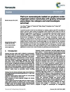
Fig. 1. Schematic cross-section of (a) regular, (b) modified, (c) side-contacted FED structures. (d) Mechanism of the reservoir function in the OFF-state. Reservoirs are heavily doped to have a low series resistance and to provide good contacts to the channel region.
electrostatic-discharge protection [5]–[7] and memory-cell applications [8], [9]. The structure of FEDs is similar to that of conventional MOSFETs with the exception of using two gates over the channel area and oppositely doped source and drain regions. However, as the channel length is scaled below 100 nm, the OFF-state current of regular FEDs increases [4]. To overcome this problem, modified FEDs (M-FEDs) have been proposed recently [10]. In this structure, oppositely doped regions called reservoirs are introduced to the source and drain areas [see Fig. 1(b)]. It has been demonstrated that FEDs have a higher speed and lower power consumption in comparison with MOSFETs [4], [11]. In this paper, the performance of M-FEDs is studied, including the band-gap-narrowing (BGN) effect. Furthermore, the possibility of replacing an M-FED with a suitable sidecontacted FED (S-FED) is investigated. The influence of the gate voltage and channel-length scaling on device performance is studied. The Ion /Ioff ratio, which is a very significant parameter in digital applications, is analyzed and compared with that of MOSFETs. We compare FED devices, including modified and side-contacted structures, with a MOSFET in terms of figures of merit, which are intrinsic speed, the energy–delay product, and the subthreshold slope, as a function of the gate length LG and intrinsic gate delay time as a function of Ion /Ioff ratio. These four metrics capture the four fundamental device parameters for logic applications, i.e., speed, switching energy, scalability, and OFF-state leakage, respectively.
0018-9383/$26.00 © 2011 IEEE
MANAVIZADEH et al.: PERFORMANCE ASSESSMENT OF NANOSCALE FIELD-EFFECT DIODES
TABLE I OPERATION MODES OF A FED
II. D EVICE S TRUCTURE A FED is a structure with two gates over its channel called GS and GD [see Fig. 1(a)] and oppositely doped source and drain regions. The gate contacts of FEDs can be biased such that either a p-n or n-p channel replaces the lightly doped or intrinsic region between the source and drain areas. Based on the gate, source, and drain voltages, five operation modes can be considered for FEDs (see Table I). The operation modes of interest are modes B and E, in which the source/channel/drain areas act as n+ -n-p-p+ and n-+ p-n-p+ structures, respectively. Fig. 1(a) shows a regular FED based on a SOI structure, where the source and the drain have n-type and p-type doping, respectively. This FED will be in the ON-state if positive and negative voltages are applied to GS and GD, respectively. By just reversing the gate-voltage polarities, the device will be turned off. In the OFF-state, the device has a structure similar to a silicon-controlled rectifier (n-p-n-p). However, as the channel length shrinks below 100 nm, regular FEDs cannot be turned off [10]. To suppress this problem, M-FEDs have been proposed [10]. In this structure, oppositely doped regions called reservoirs are introduced to the source and drain areas of regular FEDs [see Fig. 1(b)], where they assist the gate contacts to accumulate more holes and electrons under GS and GD, respectively, and induce a larger surface potential. In other words, in the OFF-state, the excess minority carrier injection takes place across the forward-biased n+ -p (source side) and n-p+ (drain side) junctions, causing an increase in the electron and hole concentrations in the p-region (under GS) and the n-region (under GD), respectively. This increase in the electron and hole concentrations obstructs the formation of a reverse-biased p-n junction in the channel. Therefore, to achieve a proper OFF-state current, excess electrons and holes under GS and GD should be reduced. The reservoirs connect the p-region under GS to the source and the n-region under GD. As a result, the forward bias of the n+ -p and n-p+ junctions decreases, and the carrier injection into the channel is reduced. This mechanism is shown schematically in Fig. 1(d). In a forward-biased FED, the drain voltage and the neighboring gate have opposite polarities; therefore, pinchoff does not occur in FEDs, and they do not suffer from hot-electron effects, unlike short-channel FETs [2], [12]. As we show in this paper, the Ion /Ioff ratio of FEDs can be at least two orders of magnitude higher than that of SOI-MOSFETs. Although the fabrication of M-FEDs is similar to the standard CMOS process, extra steps are inevitable to form reservoirs and source/drain regions. The source/drain regions can be introduced over the reservoirs using ion implantation. However,
2379
due to the demand for very shallow source/drain regions, this method may not be practically feasible. To make the fabrication of these devices more feasible, we propose an S-FED. As shown in Fig. 1(c), side contacts are created by utilizing trench technology. Creating side contacts to the source and drain areas can be performed by reactive ion etching and using an oxide layer as an etch stop. The subsequent deposition of Pt and the PtSi creation of the sidewalls can make side-contact deposition compatible with processes, which are used in regular CMOSfabrication steps. In this structure, source and drain contacts can be epitaxially grown [13]. III. M ODELING We employed the device simulator MINIMOS-NT [14] to analyze the current–voltage characteristics of M-FEDs and S-FEDs. We studied FEDs with a channel length of 75 nm, a gate length of 35 nm, a body thickness of 50 nm, and a gate-oxide thickness of 2 nm. The structure is considered to be fabricated on a buried oxide layer of 500 nm. The depths of reservoirs and source/drain regions are 50 and 25 nm, respectively [15], with a doping concentration of 1021 cm−3 and a device width of 1 μm. A. BGN Model BGN due to heavy doping is an important effect in bipolar transistors [16]. Various BGN models have been developed, including the Slotboom BGN model [17], [18], the Del Alamo BGN model [19], and the Bennett BGN model [20]. The Slotboom BGN model is widely used for the analysis of silicon devices and has been implemented in most device simulators such as MINIMOS-NT [14]. The Slotboom BGN model is used to describe the effective carrier concentration ni, eff at heavy doping using a Boltzmann statistics-based equation, despite the presence of degeneracy effects as follows: � � �Eg, app 2 2 (1) ni, eff = ni0 exp kT � � −Eg, 0 n2i, 0 = NC NV exp . (2) kT ni, 0 is the intrinsic carrier density at moderate doping levels, NC and NV are the conduction- and valence-band effective density-of-states, Eg, 0 is the band gap at moderate doping, and �Eg, app is the apparent BGN [21], which is a function of the doping level N as follows: ⎞ ⎛ �� �2 N 1 N �Eg, app = �Eg, 0 ⎝ln + + ⎠ . (3) ln N0 N0 2 The shift of the conduction- and valence-band edges is calculated by �EC · �Eg, app �Eg, app �EV = �Eg, app − �EC . �EC =
(4) (5)
�Eg, 0 , N0 , and �EC /�Eg, app are 9×10⁻⁴ eV, 1017 cm−3 and 0.5, respectively. For the given doping levels, �Eg, app ,
2380
IEEE TRANSACTIONS ON ELECTRON DEVICES, VOL. 58, NO. 8, AUGUST 2011
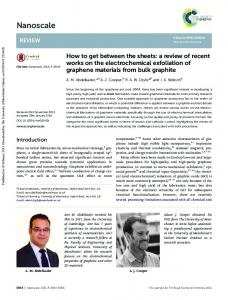
Fig. 2. IDS –VDS characteristics of MOSFETs, S-FEDs, and M-FEDs in the (a) ON- and (b) OFF-states. The insets show the band-edge profiles of the M-FED and the S-FED in the (a) ON- and (b) OFF-states.
Fig. 3.
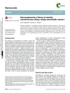
Carrier concentration profiles of the M-FED and the S-FED along the channel and 1 nm below the gate-oxide interface for the (a) ON- and (b) OFF-states.
�EC , and �EV can be approximated as 72.55×10⁻⁴ , 36.27× 10⁻⁴ , and 36.27×10⁻⁴ eV, respectively, using (3)–(5). IV. R ESULTS AND D ISCUSSION In this section, the electrical characteristics of MOSFETs, S-FEDs, and M-FEDs are compared. The scaling of these devices and the influence of short-channel effects on the performance of these devices are investigated. A. BGN Effect Fig. 2 compares the current–voltage characteristics of the M-FED with and without considering the BGN model. It is observed clearly that the predicted Ion /Ioff ratio, using the BGN model, is at least two orders of magnitude larger than that obtained with models neglecting this effect. In devices containing adjacent layers or regions with different doping concentration, doping-induced shifting of band edges can significantly influence the device characteristics [22], [23]. B. ON-State and OFF-State Characteristics Fig. 2 demonstrates that both S-FED and M-FED devices have similar current–voltage characteristics to that of a forwardbiased p-n-junction diode and a negligible OFF-state current. The ON-state current of the S-FED is slightly smaller than that of the M-FED, but its Ion /Ioff ratio is at least two orders of magnitude larger than that of the M-FED. Fig. 3 compares
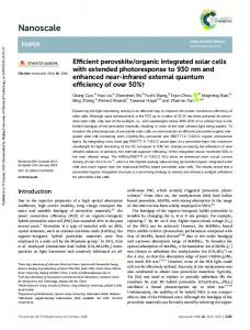
Fig. 4. Transfer characteristics of M-FEDs at different VDS . VG = VGS = −VGD .
the carrier-density profile along the M-FEDs and S-FEDs. The n+ -n-p-p+ and n+ -p-n-p+ -like behaviors can be observed in the ON- and OFF-states. In the ON-state, carrier concentrations are similar; however, in the OFF-state, the carrier concentrations are different. In this case, in the presence of the reservoirs in both structures, the forward-bias voltages of the n+ -p diode on the source side and the n-p+ diode on the drain side are reduced, and the excess minority carrier injection is reduced. In other words, by taking advantage of the n+ -p-n-p+ structure, the device is biased to maintain the silicon-controlled-rectifier mode in the OFF-state, which minimizes the leakage current. The contacts of the M-FED on the source, the drain, and
MANAVIZADEH et al.: PERFORMANCE ASSESSMENT OF NANOSCALE FIELD-EFFECT DIODES
2381
Fig. 5. Output characteristics of the M-FED as a function of the gate voltage in the (a) ON- and (b) OFF-states. The insets show the band-edge profiles along the channel of the M-FED in the (a) ON- and (b) OFF-states. VG = VGS = −VGD . The second inset in (a) shows the output characteristics in the ON-state.
Fig. 6. Output characteristics of the S-FED as a function of the gate voltage in the (a) ON- and (b) OFF-states The insets show the band-edge profiles along the channel of the S-FED in the (a) ON- and (b) OFF-states. VG = VGS = −VGD . The second inset in (a) shows the output characteristics in the ON-state.
their reservoirs can control the carrier injection to the channel, whereas in the new structure, the contacts have a weaker influence on the current, and the gates strongly affect the carrier transport through the channel. Fig. 2 also compares the output characteristics of FEDs and a MOSFET with similar geometrical parameters. Unlike MOSFETs, the drain currents of FEDs do not saturate at high drain voltages due to the absence of pinchoff in FEDs. Furthermore, the Ion /Ioff ratios of FEDs are at least two orders of magnitude higher than that of MOSFETs. The corresponding band-edge profiles along the channel of both structures are shown in the inset in Fig. 2. In both the ON- and OFF-states, the BGN effect is observed in the highly doped source and drain regions, where the band gap is smaller than that of the channel. In these structures, the reservoirs help the gates to induce a larger potential onto the channel and reduce the OFF-state current. In the case of optimized devices, the supply voltage VDD is applied between the drain and the source, i.e., VDS = VDD . A gate-voltage swing of VG from 0 V to VDD is applied between the gate and the source for transistor operation, i.e., VG goes from 0 to VDD . Ion is determined at VG = VDS = VDD , whereas Ioff is determined at VG = −VDS and VDS = VDD (VG = VGS = −VGD ). The transfer characteristics of the M-FED at different VDS are shown in Fig. 4. The subthreshold slope is approximately 140 mV/decade at VDS = 1.0 V.
C. Output Characteristics The effect of the gate voltage on the performance of both FED structures is investigated in this section. Figs. 5 and 6 show the output characteristics of the M-FED and S-FED at different gate voltages, respectively. As shown in Figs. 5 and 6, the increase in the ON-state current is slightly smaller for the S-FED because of a weaker influence of source and drain contacts. The Ion /Ioff ratio for the S-FED is at least one order of magnitude higher than that of the M-FED for various gate voltages and increases by increasing the gate voltages. This is due to more control of the gates on the ON- and OFF-state currents, where this control strongly affects the minority carrier injection in the S-FEDs. The corresponding band-edge profiles along the channel are shown in the insets in Figs. 5 and 6.
D. Channel-Length Influence We have compared the figure of merit of a MOSFET, an S-FED, and an M-FED, as a function of the channel length. The same geometrical parameters have been considered for all these structures. The results have been compared at a channel length of 35, 55, 75, 95, and 115 nm. Fig. 7 compares Ion as a function of Ioff for various channel lengths. Apparently, short-channel effects are less pronounced in FEDs, particularly for the S-FED. The Ion /Ioff ratio for the S-FED decreases from 107 to 10 as the channel length is scaled from 115 to 35 nm. Apparently,
2382
IEEE TRANSACTIONS ON ELECTRON DEVICES, VOL. 58, NO. 8, AUGUST 2011
Fig. 7. Comparison of Ion versus Ioff for the MOSFET, the S-FED, and the M-FED as a function of the channel length.
Fig. 9. Intrinsic gate delay time as a function of the physical gate length of the MOSFET and the FEDs. The inset shows the intrinsic gate delay time as a function of the Ion /Ioff ratio for various channel lengths.
Fig. 8. Intrinsic gate delay time as a function of Ioff for the MOSFET, the S-FED, and the M-FED.
for channel lengths shorter than 100 nm, FEDs show a better performance than MOSFETs. At a given Ion value, the Ioff of the FEDs is at least two orders of magnitude smaller than that of the MOSFET. E. Intrinsic Gate Delay Time The intrinsic gate delay time with respect to the Ion /Ioff ratio can be employed to compare devices with different geometrical and material parameters [24]. The gate delay time, which characterizes the switching response of a transistor, is an important metric for digital electronic applications. The gate delay time of a transistor is defined as the time taken to charge the constant gate capacitance CG to voltage VDD at constant current Ion as follows: τ=
CG VDD . Ion
Fig. 10. Comparison of the energy-delay product of a MOSFET, S-FED, and M-FED as a function of the physical gate length.
The intrinsic device speed of the MOSFET, the S-FED, and the M-FED with respect to the physical gate length is compared in Fig. 9. The gate length of FEDs is defined as the sum of two gate lengths and the spacer between them. The results shown in Fig. 9 indicate that FEDs exhibit a significant improvement over MOS devices. This improvement is primarily due to the suppression of short-channel effects in FEDs. Based on the presented data, the speed of S-FEDs is higher than that of M-FEDs at gate lengths shorter than 80 nm. The inset in Fig. 9 compares the gate delay time as a function of the Ion /Ioff ratio for the MOSFET, S-the FED, and the M-FED with different gate lengths. The results show that FEDs have a smaller gate delay time in comparison with MOSFETs at gate lengths below 100 nm.
(6)
Fig. 8 compares the gate delay time as a function of Ioff for MOSFETs, S-FEDs, and M-FEDs at VDD = 1 V. The intrinsic capacitance CG is calculated from the simulation results by the derivation of the total charge present in the channel with respect to VGS . The results shown in Fig. 8 demonstrate obvious advantages of FED devices.
F. EDP The EDP is another figure of merit important for logic applications. EDP is a design metric for optimizing both energy efficiency and high performance. A smaller value of EDP implies lower energy consumption at the same level of performance or, in other words, a more energy-efficient design. Fig. 10 compares the EDP of the MOSFET, the S-FED, and the
MANAVIZADEH et al.: PERFORMANCE ASSESSMENT OF NANOSCALE FIELD-EFFECT DIODES
Fig. 11. Subthreshold slope as a function of the physical gate length.
M-FED. Due to a higher ON-state current and a lower OFF-state current, both FEDs show a smaller EDP in comparison with MOSFETs.
G. Subthreshold Slope An important device parameter indicating the scalability of the device is the subthreshold slope. Fig. 11 compares the subthreshold slope of MOSFETs, S-FEDs, and M-FEDs as a function of the gate length. Apparently, the subthreshold slope of FEDs is steeper than that of MOSFETs for gate lengths below 100 nm.
V. C ONCLUSION The role of the BGN on the performance of M-FEDs has been investigated. Simulation results show that the Ion /Ioff ratio is at least two orders of magnitude larger than the results obtained with models neglecting this effect. To make the fabrication of M-FEDs more feasible, we propose a sidecontacted structure. Our numerical analysis indicates that S-FEDs have a slightly lower ON-state current than M-FEDs, whereas their OFF-state current shows a higher Ion /Ioff ratio than M-FEDs. Our results indicate that by appropriate selection of the applied gate voltage, the Ion /Ioff ratio can be increased to 107 for S-FEDs. Important figures of merit of FEDs for digital applications have been compared against those of MOSFETs. The results indicate that short-channel FEDs, particularly S-FEDs, outperform MOSFETs. S-FEDs can be considered as interesting candidates for future digital applications. R EFERENCES [1] D. Goldhaber-Gordon, M. S. Montemerlo, J. C. Love, G. J. Opiteck, and J. C. Ellenbogen, “Overview of nanoelectronic devices,” Proc. IEEE, vol. 85, no. 4, pp. 521–540, Apr. 1997. [2] F. Raissi, “A brief analysis of the field effect diode and breakdown transistor,” IEEE Trans. Electron Devices, vol. 43, no. 2, pp. 362–365, Feb. 1996. [3] I. Sheikhian and F. Raissi, “High-speed digital family using field effect diode,” Electron. Lett., vol. 39, no. 4, pp. 345–347, Feb. 2003. [4] I. Sheikhian and F. Raissi, “Simulation results for nanoscale field effect diode,” IEEE Trans. Electron Devices, vol. 54, no. 3, pp. 613–617, Mar. 2007.
2383
[5] S. Cao, A. A. Salman, J. H. Chun, S. G. Beebe, M. M. Pelella, and R. W. Dutton, “Design and characterization of ESD protection devices for high-speed I/O in advanced SOI technology,” IEEE Trans. Electron Devices, vol. 57, no. 3, pp. 644–653, Mar. 2010. [6] J. B. Ostinga, H. B. Heersche, X. Liu, A. F. Morpurgo, and L. M. K. Vandersypen, “Design and optimization of the SOI field effect diode (FED) for ESD protection,” Solid State Electron., vol. 52, no. 10, pp. 1482–1485, Oct. 2008. [7] S. Cao, S. G. Beebe, A. A. Salman, M. M. Pelella, J. H. Chun, and R. W. Dutton, “Field effect diode for effective CDM ESD protection in 45 nm SOI technology,” in Proc. IEEE Int. Rel. Phys. Symp., Montreal, QC, Canada, Apr. 26–30, 2009, pp. 594–601. [8] M. Amirmazlaghani and F. Raissi, “Memory cell using modified field effect diode,” IEICE Electron. Exp., vol. 6, no. 22, pp. 1582–1586, 2009. [9] Y. Yang, A. Gangopadhyay, Q. Li, and D. E. Ioannou, “Scaling of the SOI field effect diode (FED) for memory application,” in Proc. ISDRS, Dec. 2009, pp. 1–2. [10] F. Raissi and I. Sheikhian, “Nano-scale transistor device with large current handling capability,” European Patent EP1 965 437 (A1), Sep. 3, 2008. [11] I. Sheikhian and F. Raissi, “An improved differential comparator with field effect diode output stage,” J. Circuits Syst. Comput., vol. 14, no. 5, pp. 931–937, 2005. [12] J. J. Sanchez, K. K. Hsueh, and T. A. Demassa, “Drain-engineered hot-electron-resistant device structure: A review,” IEEE Trans. Electron Devices, vol. 36, no. 6, pp. 1125–1132, Jun. 1989. [13] T. A. Langdo and A. J. Lochtefeld, “Methods of fabricating semiconductor structures having epitaxially grown source and drain elements,” U.S. Patent 7 122 449, Oct. 17, 2006. [14] Institute for Microelectronics, TU WIEN, Vienna, Austria, MINIMOSNT 2.0 User’s Guide, 2002. [Online]. Available: http://www.iue.tuwien. ac.at/software/minimos-nt [15] N. Manavizadeh, F. Raissi, and E. A. Soleimani, “Study the effect of reservoir depth on the modified field effect diode performance,” in Proc. IUMRS-ICEM, Seoul, Korea, Aug. 22–27, 2010. [16] V. Palankovski, G. Kaiblinger-Grujin, and S. Selberherr, “Study of dopant-dependent band gap narrowing in compound semiconductor devices,” Mater. Sci. Eng. B, vol. 66, no. 1–3, pp. 46–49, Dec. 1999. [17] J. W. Slotboom, “The pn-product in silicon,” Solid State Electron., vol. 20, no. 4, pp. 279–283, Apr. 1977. [18] D. B. M. Klaassen, J. W. Slotboom, and H. C. D. Graaff, “Unified apparent bandgap narrowing in n- and p-type silicon,” Solid State Electron., vol. 35, no. 2, pp. 125–129, Feb. 1992. [19] J. del Alamo, S. Swirhun, and R. M. Swanson, “Simultaneous measurement of hole lifetime, hole mobility and bandgap narrowing in heavily doped n-type silicon,” in IEDM Tech. Dig., 1985, pp. 29–293. [20] H. S. Bennett and C. L. Wilson, “Statistical comparisons of data on bandgap narrowing in heavily doped silicon: Electrical and optical measurements,” J. Appl. Phys., vol. 55, no. 10, pp. 3582–3587, May 1984. [21] J. W. Slotboom and H. de Graaff, “Measurements of bandgap narrowing in Si bipolar transistors,” Solid State Electron., vol. 19, no. 10, pp. 857–862, Oct. 1976. [22] U. Lindefelt, “Doping-induced band edge displacements and band gap narrowing,” J. Appl. Phys., vol. 84, no. 5, pp. 2628–2637, Sep. 1998. [23] C. Persson, U. Lindefelt, and B. E. Sernelius, “Band gap narrowing in n-type and p-type 3H, 2H-, 4H-, 6H-SiC, and Si,” J. Appl. Phys., vol. 86, no. 8, pp. 4419–4427, Oct. 1999. [24] R. Chau, S. Datta, M. Doczy, B. Doyle, B. Jin, J. Kavalieros, A. Majumdar, M. Metz, and M. Radosavljevic, “Benchmarking nanotechnology for high-performance and low-power logic transistor applications,” IEEE Trans. Nanotechnol., vol. 4, no. 2, pp. 153–158, Mar. 2005.
Negin Manavizadeh (M’09) was born in Tehran, Iran, in 1980. She received the B.S. and M.S. degrees in solid-state physics from Khaje Nasir Toosi University of Technology (KNTU), Tehran, in 2003 and 2006, respectively. She is currently working toward the Ph.D. degree with the Department of Electrical Engineering, KNTU. Since 2003, she has worked as a Researcher with the Thin Film and Nanoelectronics Laboratory, University of Tehran, Tehran. Her research interests include micro- and nanoelectronics, and solar cells. Mrs. Manavizadeh is a member of the IEEE Electron Devices Society and IEEE Women in Engineering since 2009.
2384
IEEE TRANSACTIONS ON ELECTRON DEVICES, VOL. 58, NO. 8, AUGUST 2011
Farshid Raissi received the B.S. degree from Louisiana State University, Baton Rouge, in 1988 and the M.S. and Ph.D. degrees from the University of Wisconsin–Madison, Madison, in 1992 and 1995, respectively, all in electrical engineering. He is currently a Full-Time Associate Professor with the Department of Electrical Engineering, Khaje Nasir Toosi University of Technology, Tehran, Iran. His main research interests include fabricating digital circuits based on soliton transistors and nanoscale semiconductor devices.
Mahdi Pourfath (M’08) was born in Tehran, Iran, in 1978. He received the B.S. degree in electrical engineering and the M.S. degree from the Shariff University of Tehran, in 2000 and 2002, respectively and the Ph.D. degree in technical sciences from the Vienna University of Technology, Vienna, Austria, in 2007. Since October 2003, he has been with the Institute for Microelectronics, Vienna University of Technology, where he is currently working as a Postdoctoral Researcher. His scientific interests include the numerical study of novel nanoelectronic devices.
Ebrahim Asl Soleimani received the B.S. and M.S. degrees in physics from the University of Tehran, Tehran, Iran, in 1969 and 1971, respectively; the M.Tech. degree in physics and technology of semiconductor from Brunel University, Uxbridge, U.K., in 1976, and the Ph.D. degree in electronic engineering from Oxford University, Oxford, U.K., in 1979. He is currently a Full-Time Professor with the Department of Electrical and Comuter Engineering, University of Tehran. He has collaborated with different firms on applied projects. He is the author of a number of papers in well-rated international journals. His main research interests include device fabrication (on solar cells), device simulation, and energy.
Siegfried Selberherr (M’79–SM’84–F’93) was born in Klosterneuburg, Austria, in 1955. He received the M.S. degree in electrical engineering and the Ph.D degree in technical sciences from Vienna University of Technology, Vienna, Austria, in 1978 and 1981, respectively. Since 1984, he has been holding the authorization to teach on computer-aided design. Since 1988, he has been the Chair Professor with the Institute for Microelectronics, Vienna University of Technology. From 1998 to 2005, he was the Dean with the Faculty of Electrical Engineering and Information Technology, Vienna University of Technology. His current research interests include modeling and simulation of problems for microelectronics engineering.