Performance Evaluation of 3D Stacked Multi-Core Processors with Temperature Consideration Takaaki Hanada†, Hiroshi Sasaki††, Koji Inoue††, and Kazuaki Murakami†† †Graduate School of Information Science and Electrical Engineering, Kyushu University 744 Motooka, Nishi-ku, Fukuoka 819-0395, Japan Phone: +81-92-802-3794 FAX: +81-92-802-3796 E-mail:
[email protected] ††Faculty of Information Science and Electrical Engineering, Kyushu University 744 Motooka, Nishi-ku, Fukuoka 819-0395, Japan Phone: +81-92-802-3794 FAX: +81-92-802-3796 E-mail: { koji, murakami } @ait.kyushu-u.ac.jp,
[email protected] Abstract- 3D stacked multi-core processor is one of the applications of 3D integration technology. It achieves high bandwidth access to last level cache and allows to increase the number of cores while maintaining the package area. Although, 3D multi-core temperature increases with the number of stacked dies because of the escalating power density and thermal resistivity. Therefore, 3D multi-cores require lower clock frequencies for keeping the temperature under a safe constraint, so that performance is not always improved. In this paper, we evaluate the performance of 3D stacked multi-cores running under temperature constraints, and we show that there is a trade-off between clock frequency and parallel capability. I.
design method is a conservative and naive approach for ensuring a safe temperature without increasing cooling costs. If 3D stacked multi-cores are designed with the Thermal Design Power, the clock frequency is decreased with the number of stacked dies. Therefore, considering the processor temperature constraints, while stacking dies is expected to increase performance due to a higher number of cores and shorter wires, the required frequency decrease may lead to the opposite effect. In this paper, we evaluate the performance of 3D stacked multi-cores under a safe constraint. Then we highlight the performance trade-off between frequency and thread-level parallelism in various 3D stacked multi-cores. Finally, we evaluate 3D stacked multi-cores and 2D multi-cores with several workload for comparison. For that purpose, first, we perform processor thermal analysis in order to obtain the maximum clock frequency under temperature constraint. Then, we evaluate the performance of 2D and 3D stacked multi-cores with this maximum clock frequency through processor simulation. The main contributions of this paper are: Thermal analysis of 3D multi-cores assuming realistic temperatures; Performance evaluation of 3D multi-cores under temperature constraint using various realistic workloads. The rest of this paper is organized as follows. Section II discusses the related work. Section III explains the assumptions about 3D multi-cores made in this paper. Section IV gives thermal analysis and results. Section V provides performance evaluation. Finally, we give the conclusion of this paper and future work in Section VI.
I NTRODUCTION
Three-dimensional (3D) stacking is a novel technology which improves integration and shortens communication wires. It consists in stacking several dies and providing inter-die communications through vertical vias (e.g. Through-Silicon-Vias). By using the many vertical vias, 3D integrated circuits achieve shorter critical path and higher inter-layer communication bandwidth, thus many researchers and engineers have high hopes in this technology. One of the applications of 3D integration technology is 3D stacked multi-core processor [10]. Such a processor is constructed with conventional 2D multi-core dies and vertical shared buses. Compared with standard 2D multi-core processors, 3D stacked ones can include much more cores for a same package area and benefit from shorter wires. However, die stacking leads to temperature increase. It is because the heat density and the thermal resistance increase with the number of stacked dies. Rising temperature of integrated circuit causes negative effects: leading clock skews; increasing leakage; aging of the chip and so on. Therefore, temperature aware design is important for 3D integrated circuits. For that purpose, clock frequency selection under the Thermal Design Power is generally used [15]. This
II.
R ELATED W ORK
Many researchers have been addressing thermal issues of 3D-ICs [6][13][14][19]. Thermal issues of 3D stacked multi-cores is especially a hard challenge because of the increasing power density with the number of stacked cores. Awasthi et al. [4] discussed the thermal issues and worked on thermal analysis for 3D stacked multi-cores. They showed
1
Heat Spreader
Heat Sink
L2 Cache Bank
Through-Silicon-Via ( TSV )
Core
2D Multi-core (1Layer, 2Cores)
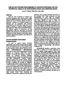
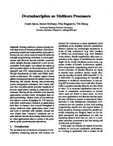
Face-to-Back Connect Fig. 1: Structure Overview of 3D Multi-Core Processor
Non-Flip Stacking
Table 1: Architecture Parameters of Multi-Core Processors
ISA Technology Node
Processor Core Alpha 21364 like
Flip Staking
3D Multi-core (2Layers, 4Cores)
Non-Flip Stacking
Flip Staking
3D Multi-core (4Layers, 8Cores)
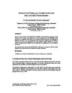
Fig. 2: Evaluated Multi-Core Processors Overviews
70 (nm) L1 I/D Cache
Table 2: Physical Parameters for Thermal Simulation
Size 64 (KByte) Latency 1.17 (ns) Associativity 2 (ways) Last Level Cache (Shared L2 Cache) 2 Cores 4 Cores 8 Cores Size 2 (MByte) 4 (MByte) 8 (MByte) Latency 2.85 (ns) 3.85 (ns) 5.41 (ns) Associativity 8 (ways) 8 (ways) 8 (ways)
Heat Sink Heat Spreader Processor Die Die-to-Die
Size (W ×D×H ) 50 × 50 × 25 (mm3 ) 30 × 30 × 1 (mm3 ) 8.0 × 7.3 × 0.033 (mm3 ) 8.0 × 7.3 × 0.002 (mm3 )
corresponding to a field in the address. In case the target bank is on a different layer from the accessing core, the shared TSV bus is used. Parameters of the considered 3D stacked multi-cores are showed in Table 1. The parameters of the L1 caches and the shared L2 cache are obtained by using the cache model named CACTI 5.3 [17]. For thermal analysis, it is necessary to consider the power. We assume that the power dissipation of a 3D multi-core is always at peak (which is actually the worst case). In this paper, we assume a base clock frequency of 120M Hz, and a base voltage of 1.10V . This voltage is referred from the ITRS road map assuming a 70nm technology [1]. Additionally, we assume that the 3D multi-core voltage depends on the frequency. In particular, we consider that the voltage varies by 0.05V per 200M Hz frequency transition. This voltage assumptions are referred from [2]. Also, in this paper, if we do consider the dynamic power, we do not include the leakage power. For mitigating the temperature, the stacking structure is an important factor in 3D multi-cores. We evaluate 2 cases of stacking structure.
that 3D stacked multi-core temperature is very high compared with 2D conventional multi-cores. They also remarked that the temperature of 3D stacked multi-cores is mitigated to some degree by using a thermal distribution oriented stacking structure. Such a temperature mitigating stacked structure is discussed in detail by Kursun et al. [9]. In terms of performance, several researchers focus on the performance of 3D-IC considering the temperature. Loi et al. [11] evaluated the performance of memory stacked processor with thermal consideration. Memory stacked processors achieve high bandwidth memory access compared with conventional processor-memory systems. Since the temperature of memory stacked processors rises with the number of stacked memory dies, the clock frequency is to be reduced accordingly to limit this increase. Their evaluation results show that memory stacked processors achieve good performance, even with temperature consideration, for memory intensive workloads. III.
Thermal Conductivity 240 (W/mK) 400 (W/mK) 28.1 (W/mK) 60.2 (W/mK)
OVERVIEW OF THE 3D M ULTI -C ORE P ROCESSOR
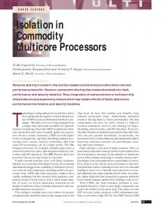
• Non-Flip : Layers are stacked with the same horizontal orientation, i.e., cores are stacked on each other and so are L2 cache banks. With this case, the dissipated power is concentrated on the cores, thus hotspots are likely to occur. • Flip : Layers are stacked with alternated horizontal orientation. Specifically, odd and even layers are oriented in opposite directions. With this case, the dissipated power is more uniformly distributed in the processor, thus hotspots should hardly occur.
In this paper, we assume a 3D multi-core which is constructed with conventional 2D multi-core dies and die-to-die connecting layers. Figure 1 shows the structure of such a 3D stacked multi-core. The dies are stacked by Face-to-Back topology, and connected to each other by vertical vias (e.g. TSVs). The die-to-die layers are filled with glue. In our evaluation, each die consists of 2 cores and a part of the globally shared L2 cache. This shared L2 cache is composed of banks, one per layer, connected through shared TSV buses. When referring the L2 cache, the bank is selected 2
2D (2Cores) 2Layers (4Cores) Flip 4Layers (8Cores) Flip
110
Non-Flip MIPS (left y-axis)
0
0.5
SP3.54 I 3 M2.5 de izl 1.52 a m ro0.51 N0 1
1.5 2 2.5 Clock Frequency (GHz)
3
3.5
4
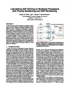
Fig. 3: Temperature of 2D and 3D Stacked Multi-Core Processors with Peak Power Dissipation
Configuration 2D 2 Cores
3D 4 Layers 8 Cores
Non-Flip Flip Non-Flip Flip
10 7.5 5 2.5
)s e ro C 2 ( D 2
)s e ro C 4 ( sr e ya L 2
FMM
Table 3: 2D and 3D Stacked Multi-Core Maximum Clock Frequency Under Temperature Constraint
3D 2 Layers 4 Cores
)s e ro C 8 ( sr e ya L 4
)s e ro C 2 ( D 2
)s e ro C 4 ( sr e ya L 2
Cholesky
)s e ro C 8 ( sr e ya L 4
)s e ro C 2 ( D 2
)s e ro C 4 ( sr e ya L 2
)s e ro C 8 ( sr e ya L 4
Radix
)s e ro C 2 ( D 2
)s e ro C 4 ( sr e ya L 2
)s e ro C 8 ( sr e ya L 4
0
CP I de izl a rm o N
Ocean
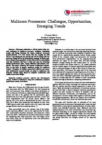
Benchmark Programs Fig. 4: Performance of 2D and 3D Stacked Multi-Core Under The Safe Temperature
Maximum Clock Frequency 3450 (MHz) 1450 (MHz) 1570 (MHz) 910 (MHz) 990 (MHz)
maximum safe clock frequencies for 2D and 3D stacked multi-cores obtained by thermal analysis. V.
P ERFORMANCE E VALUATION
For evaluating the performance, we use M IP S (Million Instructions Per Second) as an estimator. M IP S is calculated using the equation below:
Figure 2 shows the structures of the 2D and 3D stacked multi-cores used for the evaluations of sections IV. and V. IV.
Filp MIPS (left y-axis)
IPC (right y-axis)
Safe Temperature
) C ge 90 (d e r u ta 70 re p 50 m e T
30
2Layers (4Cores) Non-Flip 4Layers (8Cores) Non-Flip
T HERMAL A NALYSIS
M IP S = IP C × Fmax
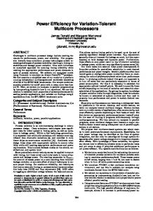
Thermal analysis is the first step of our evaluation methodology. It consists in performing thermal simulations with several clock frequencies in order to get the maximum safe frequency. This is done by using the thermal simulation tool named HotSpot 5.0 [16]. Table 2 summarizes the physical parameters for thermal simulation. Also, the physical parameters of the 3D multi-cores are referred from [6]. In this paper, we assume to use the usual cooling solutions of the general high power processors (e.g. heat sinks, heat spreaders, and so on) [3]. Additionally, the power characteristics of the cores are referred from [8]. Furthermore, we get the power figures of the L1 caches and the shared L2 cache by using CACTI 5.3 [17] assuming a 70nm technology. Figure 3 shows the temperature of the hotspots in the 2D and 3D stacked multi-cores assuming it is always the peak power which is dissipated. For this paper, we set the temperature constraint to 90◦ C. Also, we assumed an air temperature of 30◦ C. In the figure, the solid lines are the fitted curve based on the dot. The figure confirms that increasing the number of dies causes an important increase of the temperature, but also shows that the proposed thermal dissipation aware stacking structure (Flip) mitigates this increase. From the thermal analysis, we obtain the maximum safe clock frequency of the 2D and 3D stacked multi-cores. With the temperature constraint, Table 3 shows the resulting
(1)
In equation (1), IP C (Instructions Per Cycle) is calculated from cycle accurate processor simulation, and Fmax (maximum safe clock frequency) is obtained from Table 3. Then, we perform multi-core performance evaluation by using the processor simulator named M5 [5]. Additionally, we get the L1 cache and the shared L2 cache parameters by using CACTI 5.3 [17]. Table 1 summarizes these architecture parameters. Regarding the application, we selected parallelized programs from SPLASH-2 [18], a benchmark program set. Figure 4 shows the performance evaluation results under temperature constraint. In this figure, the IPC dots and the MIPS vertical bars are normalized by the 2D case. Additionally, the gray bars and dots are for the Non-Flip stacked configurations, and the white ones are for the Flip stacked configurations. As it can be seen in the figure, 3D multi-cores are not always more performant than 2D multi-cores. With programs with high parallelism (e.g. Ocean), 3D multi-cores achieve good performance. In this case, the numerous extra cores of the 3D processors can be efficiently used so that the drop in clock frequency is overcome. On the other hand, for programs with low parallelism (e.g. FMM), 3D multi-cores perform poorly compared with 2D ones. The lack of parallelism limits the usage of the extra cores of the 3D multi-cores while
3
the frequency is still reduced, so that global performance is reduced. It can be seen from these results that there is a trade-off to make between the clock frequency and the parallel capability of 3D multi-cores: ideally, the number of extra cores brought by additional layers should not exceed the parallelism level of the target application. Nonetheless, the results also show that a temperature aware stacking structure as simple as the one presented in this paper allows to use a clock higher frequency and gives therefore more margin when choosing the processor for given workloads. VI.
[7] D. Brooks, and M. Martonosi. ”Dynamic Thermal Management for High-Performance Microprocessors.” In Proc. of the Seventh International Symposium on High-Performance Computer Architecture (HPCA), pages. 171-182, Jan. 2001. [8] A. Jain, W. Anderson, T. Benninghoff, D. Berucci, M. Braganza, et al. “A 1.2 GHz Alpha microprocessor with 44.8 GB/s chip pin bandwidth.” In International Solid-State Circuits Conference (ISSCC) Digest of Technical Papers, pages 240-241, Feb. 2001. [9] E. Kursun, J. Wakil, and M. Iyengar. ”Analysis of Spatial and Temporal Behavior of Threedimensional Multi-Core Architectures Towards Run-Time Thermal Management.” In Proc. of the 12th Thermal and Thermomechanical Phenomena in Electronic Systems (ITherm), pages 1-8, June 2010.
C ONCLUSION
This paper gives performance evaluations of 3D multi-core processors with temperature consideration. 3D multi-cores have potential performance benefits due to the stacking of cores, but the power dissipation escalates with the number of stacked layers. From the evaluation, we showed that 3D multi-cores often achieve high performance processing, even if the clock frequency is scaled down for ensuring safe temperature. However, in case of low parallelism programs, the 3D multi-cores can achieve lower performance than 2D ones. For future work, we plan to use finer methods than the static thermal managements, for instance, the Dynamic Thermal Management of [7]. We also plan to consider the exact power dissipation instead of the peak power only.
[10] F. Li, C. Nicopoulos, T. Richardson, Y. Xie, V. Narayanan, and M. Kandemir. ”Design and Management of 3D Chip Multiprocessors Using Network-in-Memory,” In Proc. of the 33th Annual International Symposium on Computer Architecture (ISCA), pages 130-141, June 2006. [11] G. L. Loi, B. Agrawal, N. Srivastava, S. Lin, T. Sherwood, and K. Banerjee. ”A Thermally-Aware Performance Analysis of Vertically Integrated (3-D) Processor-Memory Hierarchy,” In Proc. of the 43rd Design Automation Conference (DAC), pages 991-996, July 2006.
ACKNOWLEDGMENT We gratefully acknowledge Prof. Lovic Gauthier Eric and our laboratory members with deepest appreciation for their feedback on the paper. This research was supported in part by Panasonic Corporation, New Energy and Industrial Technology Development Organization and the Grant-in-Aid for Young Scientists (A), 21680005.
[12] G. L. Loh. ”3D-Stacked Memory Architectures for Multi-Core Processors,” In Proc. of the 35th Annual International Symposium on Computer Architecture (ISCA), pages 453-464, June 2008. [13] K. Puttaswamy, and G. H. Loh. ”Thermal Analysis of a 3D Die-Stacked High-Performance Microprocessor.” In Proc. of the 16th ACM Great Lakes symposium VLSI (GLSVLSI), pages 19-24, May 2006.
R EFERENCES [1]
International Technology Roadmap for Semiconductors (ITRS), (http://www.itrs.net/)
[2]
intel Pentium M Data Sheet, (http://www.intel.com/)
[3]
intel Xeon 7100 Data Sheet, (http://www.intel.com/)
[4]
M. Awasthi, and R. Balasubramonian. ”Exploring the Design Space for 3D Clustered Architectures.” In 3rd IBM Watson Conference on Interaction between Architecture, Circuits, and Compilers, Oct. 2006.
[5]
N. L. Bunker, R. G. Dressings, L. R. Hus, K. T. Liam, A. G. Saudi, and S. K. Reinhardt. ”The M5 Simulator :Modeling Networked Systems.” In IEEE Micro, Vol. 26, No. 4, pages 52-60, Aug. 2006.
[6]
B. Black, M. Annavaram, N. Brekelbaum, J. DeVale, L. Jiang, G. H. Loh, et al. ”Die Stacking (3D) Microarchitecture.” In Proc. of the 39th International Symposium on Microarchitecture (MICRO), pages 469-479, Dec. 2006.
[14] K. Puttaswamy, and G. H. Loh. ”Thermal Herding: Microarchitecture Techniques for Controlling Hotspots in High-Performance 3D-Integrated Processors.” In Proc. of the 13th International Symposium on High-Performance Computer Architecture (HPCA), pages 193-204, Feb. 2007. [15] R. Rao, S. Vrudhula, and C. Chakrabarti. ”Throughput of multi-core processors under thermal constraints.” In Proc. of the International Symposium on Low Power Electronics and Design (ISLPED), pages 201-206, Aug. 2007. [16] K. Skadron, M. R. Stan, W. Huang, and S. Velusamy. ”Temperature-Aware Microarchitecture.” In Proc. of the 30th Annual International Symposium on Computer Architecture (ISCA), pages 2-13, June 2003.
4
[17] S. J. E. Wilton, and N. P. Joupages. ”CACTI: An enhanced cache access and cycle time model.” In IEEE Journal of Solid-State Circuits, vol. 31, No. 5, pages 677-688, May 1996. [18]
Architecture (ISCA), pages 24-36, June 1995. [19] Y. Xie, G. H. Loh, B. Black, and K. Bernstein. ”Design Space Exploration for 3D Architectures.” In ACM Journal on Emerging Technologies in Computing Systems (JETC), vol. 2, No. 2, pages 65-103, Apr. 2006.
S. C. Woo, M. Ohara, E. Torrie, J. P. Singh, and A. Gupta. ”The SPLASH-2 programs: characterization and methodological considerations.” In Proc. of the 22nd Annual International Symposium on Computer
5