Performance Measurements in a Manufacturing Communication System
Célio Vinicius Neves de Albuquerque Marcelo Dias Nunes Otto Carlos Muniz Bandeira Duarte Universidade Federal do Rio de Janeiro COPPE/EE - Programa de Engenharia Elétrica P.O. Box 68504 - CEP 21945-970 - Rio de Janeiro - RJ - Brasil FAX: +55 21 290.6626 - Email:
[email protected]
Abstract
This paper presents and analyses a low cost and high performance manufacturing communication system. It consists in the standard TOP profile implemented in single processor computer connected to a IEEE 802.3 LAN. High throughput is achieved by an efficient implementation architecture based on specific layer interfaces and data structures, specialized mechanisms of memory management, timer management and task scheduling. Performance measurement results show a throughput efficiency that attains, for MAC Layer user, 6 Mbit/s for a remote communication and 42 Mbit/s for loopback configuration. A throughput of 2 Mbit/s is obtained for the Presentation Layer user. The most important bottlenecks are analysed and consist, in important descending order, in the Transport acknowledgment step frequency, Transport checksum, LLC memory copy, memory management and task scheduling.
1
Introduction
Integration of the various elements in a manufacturing system has become an important issue. This has led to the development of Computer Integrated Manufacturing (CIM) concepts [1], where proper communication is necessary to ensure adequate functioning of all the elements. CIM was conceived in order to allow control and analysis of business data as well as technological data, faster design and development cycles for more sophisticated products and flexible manufacturing systems. Two communication protocols, namely, Manufacturing Automation Protocol (MAP) [2] and Technical and Office Protocols (TOP) [3], have emerged as a standard approach to enable easy and effective communication between the elements in CIM environments. MAP/TOP specification provides a standard regarding all the aspects related to the communication between end systems. Rather than specifying new protocols, MAP/TOP are based on international standards adopted by ISO, specifically the Reference Model for Open Systems Interconnection (RM-OSI) [4,5]. The RMOSI defines a seven layered architecture structured in a hierarchical added value form. The high bandwidth provided by the Local Area Networks (LAN) has moved the performance bottleneck to the protocol processing time. Several works [6,7,8] have stated that high throughput depends on a careful protocol implementation. Some authors exploit the intrinsic protocol parallelism [9,10,11], others propose completely new protocols [12]. Nevertheless, this work deals with the problem of implementing the standard TOP communication profile efficiently in a low cost and single processor environment. This paper presents an implementation architecture of a TOP profile and its performance measurements in a local area network (LAN) environment. In order to achieve high performance communication protocols, an implementation architecture is defined. This architecture is based on specific layer interface and data structures, specialized modules of memory management, timer management and task scheduling. The proposed implementation architecture privileges flexibility, modularity and weak coupling between adjacent layers, minimizes the necessary retransmission buffers and takes into account the memory fragmentation. The measurements show a good performance and analyse the throughput due to each layer processing time, checksum mechanism and acknowledgment step frequency. This work is organized as follows. Section 2 describes TOP profile and the implemented features of each layer. Section 3 presents the implementation architecture. Its performance measurements are given in Section 4. Finally, conclusions are presented in Section 5.
2 Manufacturing Protocol Profiles CIM organizational hierarchy (Figure 1) is defined by the International Standards Organization (ISO) Reference Model for factory automation. This model supports six hierarchical levels: the Equipment Level (realization of commands to the shop floor equipment - robots, conveyors, vehicles, tools, etc.), the Station Level (numerical controllers, programmable logic controllers, etc., which direct and coordinate the activity of the shop floor equipment), the Cell Level (supervision of the various supporting devices), the Section/Area Level (coordination of production and resource allocation), the Facility/Plant Level (production planning and scheduling), and the Enterprise Level (corporate management).
OFFICE COMMUNICATION LEVEL
TOP
CAD/CAM WORKSTATION(S)
SECTION / AREA LEVEL
MAIN FRAME COMPUTER
MAP
SECTION 1 CONTROLLER
SECTION 2 CONTROLLER
SECTION N CONTROLLER
MAP
CELL LEVEL
STATION LEVEL
TOP
FACILITY HOST COMPUTERS
MICROCOMPUTER DATA CONTROL POINT
MICROCOMPUTER DATA CONTROL POINT
MICROCOMPUTER DATA CONTROL POINT
#1
#2
#N
MAP
CNC
ROBOT
PLC
CONTROLLER
CONTROLLER
CONTROLLER
EQUIPMENT LEVEL
ROBOT
Figure 1: CIM Organizational Hierarchy MAP and TOP protocol profiles were specified as standards for manufacturing environments allowing different shop floor and computer equipments to communicate. MAP first appeared in 1986, when General Motors (GM) begun to apply the concepts of CIM to its operations, and realized that communication was a bottleneck between devices on the plant floor. MAP has been specifically oriented to the needs of CIM, providing the communication which takes place on the factory floor between programmable devices, cell controllers and area or section computers, as depicted in Figure 1. The Boeing Company started work on the set of protocols which have evolved
Application
MHS
ACSE
RTSE
FTAM
Presentation
OSI Presentation Protocol
Session
OSI Session Protocol
Transport
OSI Transport Class 4
Network
CLNS ES-IS and X.25 PLP
IEEE 802.2 (LLC) Data Link IEEE 802.3 (Ethernet) Physical
Figure 2: OSI Reference Model with the TOP profile
into TOP by the same time GM began defining MAP. TOP's main goal is to encompass everything but the manufacturing environment, accelerating the availability of multivendor economical, interoperable, off-the-shelf computing systems, devices and components. It supports the transfer of files between different machines in the production and office environments, specifying standardized data formats. Figure 1 shows TOP's place in the organizational hierarchy and Figure 2, its layered protocol stack.
Below is a brief overview of each layer and the implemented protocol suite: •
Medium Access Control (MAC) Sublayer: The Institute for Electrical and Electronic Engineers (IEEE) has created a family of lower layer protocols for LANs. This set of protocols is called IEEE 802, and they are aimed at the needs of LANs. This work uses as TOP MAC Sublayer the IEEE 802.3 protocol - Carrier Sense, Multiple Access with Collision Detection (CSMA/CD) for 10 Mbit/s Ethernet media. This sublayer directly accesses a set of freeware routines, known as Packet Driver SPEC, which support a large number of communication controller cards. NE2000 drivers were used.
•
Logical Link Control (LLC) Sublayer: IEEE 802.2 standard specifies a logical link control for use with any one of the other medium access control standards. There are three different types of LLC. LLC Type 3 is acknowledged connectionless. LLC Type 2 is based on the High-level Data Link Control (HDLC) protocol. It requires a connection establishment and provides flow control and error recovery functions. LLC Type 1 is unacknowledged connectionless and allows, besides point-to-point links, multicast and broadcast facilities. This implementation regards only LLC Type 1.
•
Network Layer: The Connectionless Mode Network Service (CLNS) is used with the LAN specifications. The reason for this choice is that the datagram approach is much more flexible and robust when connecting multiple heterogeneous networks together, an important aspect of TOP. The CCITT Recommendation X.25 Packet Level Protocol (PLP) was implemented, although it was not considered in this analysis. TOP also specifies the End System to Intermediate System (ES-IS) Exchange Protocol, which provides services performing dynamic routing and updating of table information. However, this protocol will not be considered further here.
•
Transport Layer: The purpose of a Transport Service in TOP environments is to provide reliable and optimized transparent data transfer between end nodes. This layer must do whatever is necessary to bring the Quality of Service provided by the Network Layer up to the level required by the Transport Service users. OSI defines five classes of protocols (0 to 4) to guarantee transferred data integrity, Class 4 being specified by TOP. Transport Class 4 provides a connection oriented service with flow control, error detection (through checksum) and recovery (through retransmission), multiplexing/demultiplexing, segmentation/reassembly, numbering and concatenation/separation facilities.
•
Session Layer: The standard for this layer is the ISO Basic Connection Oriented Session Protocol. This protocol supplies user-oriented services of dialogue control, synchronization/resynchronization, activity management, negotiated release and half/full duplex data transfer. TOP only requires implementations to provide the Kernel functional unit and the Duplex functional unit.
•
Presentation Layer: The ISO Presentation Protocol is used as a standard for this layer. The presentation layer allows many data representations to be used among communicating application entities. This adds much flexibility in system integration, while relieving the applications of data formatting functions. Thus, it fulfills some requirements of CIM information formatting and sharing. Nevertheless, the considered presentation protocol implements only the Kernel functional unit.
•
Application Layer: This layer utilizes the services offered by lower layers to release the application process, so that the way in which data is addressed and delivered becomes transparent. It is within this layer that the system meets the end-user interface. Several application service element standards were implemented: Association Control Service Elements (ACSE), Reliable Transfer Service Elements (RTSE), File Transfer Access and Management (FTAM) and Message Handling Service (MHS).
In this work, the throughput measurements were realized by a specialized user on top of each layer up to the Presentation Layer. Application Protocol performance measurements will be addressed in future works.
3
The Implementation Architecture
High performance and reliable data transfer in manufacturing environment are the main objectives of TOP implementation. Since this system's first protocol implementation work [13], it became clear that a careful implementation was necessary and that memory copy should be avoided. Hence an efficient implementation architecture was defined [14] in order to obtain high performance. Application
ASE ASE ASE
ACSE
N 2
1 ASE - ASE Interface ASE - PRES Interface
ACSE - PRES Interface
Memory Manager
Presentation P-S Interface
Session Task Scheduler
S-T Interface
Transport T-N Interface
Timer Manager
Network N-L Interface
LLC L-M Interface
MAC
Figure 3: The Implementation Architecture.
3.1
Interface Data Structures
There are essentially two basic ways of implementing interlayer communication: procedure calls and synchronous/asynchronous message exchanges. Procedure call is certainly the most efficient mechanism but implies on a heavily coupled system. Synchronous interlayer communication is not suitable for single process environments. Asynchronous communication is usually modeled by paired (input/output) message FIFO (first in, first out) queues. This implementation architecture defines a standard interface between layers (Figure 3). This interface consists of a pair of FIFO queues per connection and a set of data structure access procedures. It aims at normalizing the access to the services offered by adjacent layers, allowing flexibility, modularity and weak coupling between layers. This independence simplifies the division of the tasks of implementation, maintenance and updating of each layer protocol and leads to a better system management. Each FIFO element (Figure 4) is represented by a fixed size structure called Primitive Structure containing the following three fields: • Primitive Structure Pointer - used for linking with the next FIFO element; • Primitive Name - name of the incoming/outgoing service primitive; • Parameter Structure Pointer - pointer to a structure that contains the current primitive parameters which is called Parameter Structure. Primitive Structure Primitive Structure Pointer
Parameter Structure
Primitive Name Primitive Parameter Pointer
Parameter Structure Pointer Parameter Pointer
Parameter
User Data Length User Data Pointer
User Data
Number of Alocations
Figure 4: Interface Data Structures. A connection setup corresponds to instantiating a pair of queues in the interface through where all service primitives corresponding to that connection are transferred. However, Application Layer is unique in the sense that it is composed by a sort of Common (ACSE, ROSE, RTSE) and Specific (MHS, FTAM, ...) Application Service Elements (ASE) which can be associated in many ways with each other and with the Presentation Layer. The Application-Presentation Layer communication is performed by ACSE and another service element. Therefore, some queues were created, namely, the ACSE-PRES and ASE(n)-PRES queues in the Application-Presentation interface, and the ACSE-ASE(n) and ASE(n1)-ASE(n2) queues for the interface between Application Service Elements, where n identifies a service element.
3.2
Protocol Control Information - PCI
A common processing for all layers, related to the communication between peer entities, is to insert/remove PCI into/from SDUs (Service Data Units). There are many methods of inserting PCI to SDUs [8,14], for example, copy, maximum allocation and chaining.
SDU PCI
PCI
SDU
Copy
SDU
(a) copy
SDU PCI PCI
SDU
(b) maximum allocation
PCI
(c) chaining
Figure 5: PCI inserting techniques. The insertion of PCI by copy (Figure 5a) consists in: 1. allocating a memory region with a length corresponding to PCI plus SDU sizes; 2. filling up the PCI and copying the SDU; 3. releasing the previous SDU. Copying data to and from buffers between protocol layers in general represents significant overhead [8,13,14,15]. Besides, the copying time is heavily dependent on SDU size. All these have a critical impact on performance. The maximum allocation technique of inserting PCI (Figure 5b) consists in allocating a sufficient memory region to hold the highest layer SDU plus the headers of all lower layers. Nevertheless, this procedure can lead to a great memory waste, because the maximum frame length would necessarily have to be reserved. This scheme also introduces the need for copies to perform some basic mapping functions like segmentation and concatenation. Another argument against the use of this procedure is the need for the upper layer to know the maximum frame size that can be sent. This fact goes against the layer independence principle supported by OSI model [5,16]. The chaining method of inserting PCI (Figure 5c) avoid data copy and waste of memory, consisting in: 1. allocating and filling up a PCI-size memory region; 2. associating this region to a chaining structure; 3. chaining this structure to the received SDU structure. This approach seemed to be the best way of inserting PCI. Each queue is formed by a basic element composed of chained data structures, defined in order to avoid data copy, a relevant factor of degradation in communication system performance. Figure 4 shows the implemented data structures which base upon pointers and sets apart fixed size structures from variable size structures, to make possible a more efficient memory management. To implement this feature, the Parameter Structure was defined [14,19] containing the following five fields: • Parameter Structure Pointer - used for linking with other Parameter Structure; • User Data Pointer - pointer to (part of) the primitive user data parameter; • User Data Length - length in bytes of the respective user data parameter; • Parameter Pointer - pointer to the other primitive parameters; • Number of Allocations.
The Number of Allocations field plays an important role for the system. It avoids several retransmission copies when protocols based on error recovery by retransmission were used (Data Link, Transport, Session and RTSE protocols). This field is incremented/decremented every time a layer allocates/deallocates that structure. The corresponding retransmission buffer is released from memory only when this field reaches zero. The Memory Manager is responsible for controlling this property. The interface between the MAC and LLC Data Link sublayers comprises a pair of circular buffers, where the data to be sent to the communication controller are copied in a contiguous way. The controller is responsible for transmission over the physical medium.
3.3
Memory Management
The insertion/removal of PCI into/from SDUs by each layer (or sublayer) necessarily requires an efficient memory management, with the purpose of attaining a good performance. It is also important that the segmentation/reassembly of data be possible without the need for copies, but just with some pointer manipulation. These constraints have led to the implementation of a specific and optimized Memory Manager [19]. In order to avoid the excess of fragmentation, this module divides memory into transmission and reception regions. It is possible because transmission and reception flows are independent. These regions are still subdivided in three parts (Primitive Structure, Parameter Structure and data regions), allowing fixed and variable size memory allocations/deallocations. Optimized algorithms are used, taking into account the specific behavior of an OSI system.
3.4
Task Scheduling
The system's first version had a main procedure which checked whether the interface queues were not empty, i.e., if there were any elements (service primitives) to be processed. This procedure proved to be too much time consuming. A great improvement in performance was achieved with the creation of a Task Scheduler module [19]. This module consists of a single queue holding the sequence of tasks ready to be executed. A protocol is easily defined by its State Machine, where from a certain event (receipt of a service primitive) and the "current state", some tasks are executed (or not) and another state is reached (or not), originating (or not) one or more new events (sending of primitives to adjacent layers). This way, in the architecture described, every time a primitive is put into one of the interface queues (creation of an event), the corresponding execution task for this primitive is put into the Task Scheduler queue. The atomization required in the state machine execution is also easily obtained.
3.5
Timer Management
Protocol implementation includes timer-based procedures which are used in error recovery routines, connection establishment and release time-out control, etc. The Timer Manager implementation follows Varghese and Lauck proposal [20], where an analogy with a real clock is simulated by a cyclic counter. This implementation proved to be very efficient, avoiding unnecessary logical checks at each hardware interrupt, thus allowing the creation of a great number of run-time
timers. In the implemented architecture, a time-out is considered as a service primitive, that is, timeout indication (event) is put into the appropriate interface queue, and the corresponding task into the Task Scheduler queue.
4
Performance Measurements
The implemented system is coded in C language and runs on IBM-PC-like personal computer environments using DOS operating system. Table 1 shows the number of code lines per layer and its respective object code size (without debug information). The basic measurement scenario consisted of two identical 33 MHz 486 DX processors connected to a IEEE 802.3 local area network through NE2000 network adapters. Table 1: Number of code lines per layer and its respective object code size. Layer / Module Memory Manager Task Scheduler Timer Manager MAC LLC CLNS TP4 Session Presentation
Code Lines Number 965 155 350 1120 1240 2290 3560 15130 2930
Object Code Size (bytes) 9K 2K 3K 3K 4K 15 K 65 K 177 K 22 K
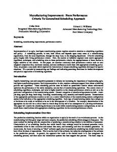
This performance analysis emphasizes on the throughput achieved by each layer user. Throughput is defined as the total useful information transferred (messages without headers and tails) per unit time. The total information amount transfer time should be measured from the instant the originator issues the first message until the recipient receives the last one. However, as this requires a distributed measurement system, another measurement methodology was employed. It consists in computing, at the originator, the data transfer time interval between the first message transmission and receipt of the last message reply. The elapsed time measurement approach makes use of PC tick-based function, providing a 55 ms accuracy. Therefore, in order to make the measurement error negligible, an information amount of 10,000 frames is transferred. In case of connection-oriented protocols, no setup/release time measurements were performed. Furthermore, both computers were dedicated to the data transfer between them. The transfer is memory-tomemory to eliminate any effects from external I/O devices. The measurements also include overheads introduced by lower layer headers. This overhead reaches 33 bytes for Presentation Layer user. In fact, the measurements are lower bound throughputs because they include the user processing time due to message creation/destruction, message insertion/removal into/out of queues, memory allocation/deallocation, etc. Figure 6 shows the throughput, in kbit/s, for the Packet Driver, MAC, LLC and CLNS Layer users. Various message sizes are used, ranging from 128 bytes to 1024 bytes.
6
Throughput (Mbit/s)
5 4
Packet Driver MAC LLC CLNS TP4 Session Presentation
3 2 1 0 0
128
256
384
512
640
768
896
1024
1152
Size (bytes)
Figure 6: Throughput versus message size. The maximum theoretical IEEE 802.3 LAN throughput is 6Mbit/s and 9.8 Mbit/s for minimum and maximum frame sizes, respectively. These throughputs may not be achieved by most of the available adapters. A specialized user software was developed to measure the Packet Driver access routines performance. Its throughput is practically due to data transfer from microcomputer memory to controller card (through copy or direct memory access), and vice-versa, since the standard interface, the memory and timer managers and the task scheduler were not utilized. By this way, the time spent specifically with the transmission routine (Tsend) can be estimated. For example, with 1024 byte frame: Tsend = Tmem + Ttx = 1.4 ms, where Tmem is the time spent in data copy from memory to card, and Ttx is the time spent by the card to effectively send the data. In general, this is the initial system limitation.
Sender
Receiver
Sender
Receiver
Presentation
Presentation
Presentation
Session
Session
Session
Tranport
Tranport
Tranport
CLNS
CLNS
CLNS
LLC
LLC
LLC
L-M Interface
L-M Interface
L-M Interface
MAC
MAC
Memory Copy (a)
MAC Communication Medium (b)
Figure 7: Measurement Scenarios. (a) Internal Loopback, (b) Connected by LAN.
As depicted in Figure 6, as the frame size increases, throughput reaches approximately 6 Mbit/s. This result shows protocol processing time negligible when compared to transmission time (Tsend), for large frames, i. e., Packet Driver access routines and LAN adapter constrain system throughput. Hence, only single computer measurements will be considered further here. A special loopback feature was developed at the Packet Driver level, consisting in frame copies from the transmission buffer to the reception buffer, according to Figure 7. It is important to emphasize that, within this configuration, Tsend is replaced by the copy time Tcopy and transmission/reception processing occurs on the same microcomputer. Just as an example, this time is about 0.22 ms for 1024 byte frames. Figure 8 shows that the system's performance improvement achieved with this new configuration. As an example, MAC sublayer throughput was about 43 Mbit/s, that is, approximately 7 times greater than the previous configuration throughput, limited by Tsend. 45
MAC LLC CLNS
40
Throughput (Mbit/s)
35 30 25 20 15 10 5 0 0
128
256
384
512
640
768
896
1024
1152
Size (bytes)
Figure 8: Throughput versus message size (loopback scheme). All communication controllers require sending data to be in a contiguous memory area. Thus, LLC sublayer performs an unavoidable copy of chained data to a contiguous memory region (transmission buffer in LLC-MAC interface). This data copy is an important performance degradation factor, responsible for a frame size dependent decrease in throughput. Mem. Manag. 16%
Mem. Manag. 12%
Task Sched. 6%
Task Sched. 10%
Others 16%
Copy 62%
Others 16%
Copy 62%
(a) originator
(b) recipient
Figure 9: LLC sublayer processing a 1024 frame length. In order to visualize the actual limitation introduced by copy, Figure 9 shows two pie charts for the specific LLC sublayer processing. It is also observed that memory allocation/deallocation and Task Scheduler queue insert procedures spend a considerable processing-time portion.
Others 35% Others 56%
Task Sched. 12%
Mem. Manag. 32%
Mem. Manag. 53%
Task Sched. 12%
(a) originator
(b) recipient
Figure 10: CLNS layer processing a 1024 packet length. The CLNS Layer was initially implemented in an attempt to interact with connection-oriented transport (TP4) and data link (LAP-D) services, with the purpose of mapping the transport/network and network/data link interface primitives in CLNS primitives. This mapping requires many memory allocations/deallocations, which consume a great portion of time, as can be depicted in Figure 10. 3
Throughput (Mbit/s)
TP4 Session Presentation 2
1
0 0
128
256
384
512
640
768
896
1024
1152
Size (bytes)
Figure 11: Transport, Session and Presentation user's throughput versus message size. The Transport Layer is responsible for the greatest protocol performance decrease (Figure 11). This was already expected because it is the Transport Layer in data transfer phase, for the TOP protocol profile, that executes the greater number of functions [18]. Detection and error recovery services implementation requires the use of a checksum mechanism, and its computational overhead can be quite high. Figure 12 shows the performance degradation introduced by the checksum. The bar chart proves the strong dependence between checksumming and frame size. Task Sched. 6%
Mem. Manag. 21%
100
Task Sched. 9%
Others 33%
Others 23%
80 60
Mem. Manag. 27%
40 20
Checksum 50%
(a) originator
Checksum 31%
(b) recipient
0 128
256
512
1024
(c) checksum vs. message size
Figure 12: Transport layer processing time for 128 bytes message length.
This protocol requires the transfer of Acknowledgment Transport Protocol Data Units (AKTPDUs) for each DT-TPDU received, and this procedure overcharges system's processing. Acknowledgments are tied to window flow control, and a window size of 8 was used. Figure 13 emphasizes the influence of acknowledgments exchange. To perform this measurements, checksum computing was disabled. Different acknowledgment steps were used, allowing one, two, three and four outstanding TPDUs. 7
TP4-AK4 TP4-AK3 TP4-AK2 TP4-AK1 TP4
6
Throughput (Mbit/s)
5 4 3 2 1 0 0
128
256
384
512
640
768
896
1024
1152
Size (bytes)
Figure 13: Transport user's throughput versus message size for various acknowledgment steps. Finally, the Session and Presentation Layers execute, in the data transfer phase, a common processing for all layers: service primitives receipt, decoding and treatment. They spend a minimum processing time due to interface management (queue checks and elements insertion/removal), memory management (allocations/deallocations) and state machine execution, which cause a performance loss at each layer.
5
Conclusions
In this work an efficient TOP communication system was presented. Its implementation architecture was described, which is based on: • asynchronous message interlayer communications modeled by paired FIFO queues. This results in a weak coupling between adjacent layers and a high modularity; • interface data structures with pointers. Copies are avoided for interlayer communication, segmentation and retransmission buffers; • a memory manager that attains high performance separating transmission and receiving memory regions. Fixed and variable size buffers allocations/deallocations are processed differently. Fragmentation is kept as a minimum; • a task scheduler that avoids unnecessary queue tests and take advantage of required atomicity of some functions; • a timer manager efficiently implemented and considered as a service primitive. The measurement results show that the system performs well attaining almost the maximum throghput at the MAC Layer user (6 Mbit/s). In a loopback configuration this layer throughput have reached 42 Mbit/s. Also in a loopback configuration the throughput for Presentation Layer user was 2 Mbit/s, when TP4 was configured for an acknowledgment step of one and checksum computation. With an acknowledgment step of four and no checksum the Presentation Layer user throughput reaches approximately 6 Mbit/s.
The unavoidable copy realized by the LLC Layer has shown that memory bandwidth is an important issue to obtain higher performane. It takes 62% of the total LLC processing time. The Transport checksum is too time consuming and justify a specialized hardware assists. The time wasted in processing acknowledgments is very important. Blocking the acknowledgments influences the performance results. The throughput was multiplied by a factor greater than two when acknowledgment step frequency was divided by a factor of four. The throughput results are quite good and fits well for most of the nowadays industrial applications.
Acknowledgments Prof. Marcelo Luiz Drumond Lanza, Prof. João Amaro Baptista Pereira, Luis Felipe Baginski, José Ferreira de Rezende, Rainer Schatzmayr, Rogério Leone Teixeira da Cunha, Fernando Mascarenhas Cavalcanti de Barros, Frederico dos Santos Liporace, Calixto Damian Neto and Marcelo Macedo Achá have all contributed to the implementation of parts of the system.
References [1] [2] [3] [4] [5] [6] [7]
[8] [9]
[10] [11]
[12]
L. J. McGuffin, L. O. Reid and S. R. Sparks, "MAP/TOP in CIM Distributed Computing", IEEE Network, vol. 2, no. 3, pp. 23-31, May 1988. "MAP 3.0 Implementation Release". "TOP 3.0 Implementation Release". The International Organization for Standardization, Data Processing, "OSI Systems Interconnection Basic Reference Model", ISO Doc. DIS7498, 1985. J. D. Day and H. Zimmerman, "The OSI Reference Model", Proc. of the IEEE, vol. 71, no. 12, pp. 1334-1340, Dec. 1983. D. D. Clark, V. Jacobson, J. Romkey and H. Salwen, "An Analysis of TCP Processing Overhead", IEEE Commun. Mag., vol. 27, no. 6, pp. 23-29, June 1989. W. A. Doeringer, D. Dykeman, M. Kaiserwerth, B. Werner Meister, H. Rudin and R. Williamson, "A Survey of Light-Weight Transport Protocols for High-Speed Networks", IEEE Trans. Commun., vol. 38, no. 11, pp. 2025-2039, Nov. 1990. L. Svobodova, "Implementing OSI Systems", IEEE J. Selected Areas Commun., vol. 7, no. 7, pp. 1115-1130, Sept. 1989. O. G. Koufopavlou, A. N. Tantawy and M. Zitterbart, "Analysis of TCP/IP for High Performance Parallel Implementations", Proc. 17th Conference on Local Computer Networks, Minneapolis, Minesota, Sept. 1992, pp. 576-585. M. Zitterbart, "Parallel Protocol Implementation for High Speed Networks", in Proc. SBT/IEEE Int. Telecommun. Symp., Rio de Janeiro, Brazil, Sept. 1990, pp. 260-264. C. Papadopoulos, G. M. Parulkar, "Experimental Evaluation of SunOS IPC and TCP/IP Protocol Implementation", IEEE ACM Trans. Networking, vol.1, no. 2, pp. 199-216, Apr. 1993. A. N. Netravali, W.D. Room and K. Sabnani, "Design and Implementation of a High Speed Transport Protocol", IEEE Trans. Commun., vol. 38, no. 11, pp. 2010-2024, Nov. 1990.
[13]
[14]
[15] [16] [17] [18] [19] [20]
L. F. Baginski, F. M. C. de Barros, R. Schatzmayr and O. C. M. B. Duarte, "Implementação e Análise de Desempenho em um Sistema de Transferência de Dados", in X Congresso da Sociedade Brasileira de Computação, Vitória, Brazil, July 1991, pp. 157-169. L. F. Baginski and O. C. M. B. Duarte, "Um Modelo de Implementação de Alto Desempenho para Sistemas Abertos", in IX Congresso da Sociedade Brasileira de Telecomunicações, São Paulo, Brasil, Sept. 1991, pp. 1941-1945. C. N. Woodside and J. R. Montealegre, "The Effect of Buffering Strategies on Protocol Execution Performance", IEEE Trans. Commun., vol. COM-37, pp. 545-554, June 1989. L. Svobodova, "Measured Performance on Transport Service in LANs", Comput. Networks ISDN Syst., vol. 18, no. 1, pp. 31-45, 1989. A. S. Tanenbaum, "Computer Networks", Englewood Cliffs, NJ: Prentice-Hall, 1988, 2nd ed. W. T. Strayer, A. C. Weaver, "Performace Measurements of Data Transfer Services in MAP", IEEE Network, vol. 2, no. 3, pp. 75-81, May 1988. L. F. Baginski, "Ambiente de Implementação para Sistemas de Alto Desempenho", Master Thesis, PEE-COPPE/U.F.R.J., Jan. 1992. G. Varghese and T. Lauck, "Hashed and Hierarchical Timing Wheels: Data Structures for the Efficient Implementation of a Timer Facility", in Proc. 11th ACM SIGOPS Symp. on Operating Systems Principles, Austin, TX, 1987, pp. 25-38.