Performance of End-to-End Mobility Management in Satellite IP Networks Pulak K Chowdhury, Mohammed Atiquzzaman School of Computer Science University of Oklahoma Norman, OK 73019-6151 Email: {pulak, atiq}@ou.edu
William Ivancic Satellite Networks & Architectures Branch NASA Glenn Research Center, 21000 Brookpark Rd. Cleveland, OH 44135 Email:
[email protected]
Abstract— IETF has developed Mobile IP to support mobility of IP hosts at the network layer. The National Aeronautics and Space Administration has implemented Mobile IP to handle handovers in space networks. Due to a number of limitations of Mobile IP, such as high handover latency, packet loss rate, and conflict with existing network security solutions, a new IPdiversity based mobility management scheme, called SIGMA, has been developed through collaborative efforts of NASA and University of Oklahoma. In this paper, we illustrate the performance of SIGMA for managing handovers in space networks. We show by simulation that SIGMA extends network connectivity from space to ground, and ensures smooth handover between spacecrafts for different space network scenarios.
I. I NTRODUCTION Future space communications will be based on commercial off-the-shelf Internet technology in order to reduce costs. This will also extend existing Internet over the space. Spacecrafts (like satellites) will communicate with ground stations on Earth and among themselves to carry data traffic by setting up end-to-end connections. Satellites can be classified into three types depending on the altitude: Low Earth Orbit (LEO), Medium Earth Orbit (MEO) and Geosynchronous Earth Orbit (GEO). GEO satellites are stationary with respect to Earth, but LEO and MEO satellites move around the earth, and are handed over between ground stations as they pass over different areas of Earth. This is analogous to mobile computers being handed over between access points as the users move in a terrestrial network. LEO satellite systems have some important advantages over GEO systems as the component of next generation Internet [1]. However, due to the non-geostationary characteristics and high speed movement of LEO satellites, ongoing connections through a satellite has to be frequently transferred to a new spotbeam or satellite. Transfer of a connection to a new spotbeam or satellite is called handover. Three types of link layer handovers are observed in LEO satellite systems [1]: (a) Satellite handover, (b) Spotbeam handover, and (c) Inter Satellite Link (ISL) handover. Moreover, it may happen that a connection endpoint (satellite or user terminal) has to change its IP address due to high rotational speed of LEO satellites. The research reported in this paper was funded by NASA Grant NAG32922.
In that case, to keep ongoing communications alive, a network layer handover is also required. Existing literature review shows that most of the research in the area of satellite handover is on link layer handovers [1], [2]; network layer handover issues have not investigated in depth. National Aeronautics and Space Administration (NASA) is currently studying, testing and evaluating the use of Internet technologies and protocols (specially Mobile IP (MIP) [3] (developed by IETF)) for space communications [4]. Cisco along with NASA has developed a Mobile Router which contains all Mobile IP functionalities to support satellite based data communications [5]. However, MIP suffers from a number of drawbacks in a mobile network environment. The most important ones identified to date are high handover latency, high packet loss rate during handover, inefficient routing, conflict with security solutions (like IPsec) and requirement for change in Internet infrastructure. These drawbacks of MIP in handling handover have been extensively studied in the literature, and several improvements [6] of MIP based handover scheme have been proposed to solve the existing drawbacks. In spite of these improvements to MIP, there are still unsolved problems during handover. To address these problems, we earlier proposed a novel transport layer based end-to-end mobility management scheme called SIGMA [7]. This scheme minimizes handover latency and packet loss with minimum signaling overhead during handover by exploiting IP diversity to achieve soft handover. IP diversity refers to having multiple IP addresses in one mobile host. It is important to note that SIGMA can be used with any transport layer protocol that supports IP diversity. For illustration purposes, we use SCTP (Stream Control Transmission Protocol), which supports IPdiversity using multihoming (TCP or UDP does not support IP diversity), as our underlying transport layer protocol. Advantages of SIGMA in satellite environments have been described in our previous work [8]. In this paper, we use some interesting satellite scenarios to show the performance of SIGMA in satellite networks. When a satellite looses link layer connection with the ground station, we consider three scenarios to keep the IP level ongoing connections alive using ISL by connecting to neighboring LEO or GEO satellite. We show that, in order to maximize throughput during those scenarios, the connection should always be handed over to the
1-4244-0357-X/06/$20.00 ©2006 IEEE
This full text paper was peer reviewed at the direction of IEEE Communications Society subject matter experts for publication in the IEEE GLOBECOM 2006 proceedings.
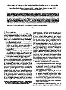
A. Handover Procedure of SIGMA A typical satellite handover in SIGMA (using SCTP as the transport protocol) is shown in Fig. 1, where the Mobile Host (MH) is a multi-homed satellite connected with the Internet through two ground stations. Correspondent node (CN) is a single-homed node sending traffic to MH, which corresponds to the services like file downloading or web browsing by mobile users. The handover process of SIGMA can be described by the following steps [7]: STEP 1: Obtain new IP address Refer to Figure 1 as an example, the handover preparation procedure begins when the satellite moves into the overlapping radio coverage area of two adjacent ground stations. Once the satellite receives the router advertisement from the new access router (IP Router B in Fig. 1), it should begin to obtain a new IP address. STEP 2: Add IP addresses into the association After the satellite obtained the new IP address by STEP 1, it notifies CN about the availability of the new IP address through SCTP Address Dynamic Reconfiguration option. STEP 3: Redirect data packets to new IP address When the satellite moves further into the coverage area of next ground station (current ground station in Fig. 1), CN can redirect data traffic to new IP address to increase the possibility that data can be delivered successfully to the satellite. STEP 4: Delete or deactivate obsolete IP address When the satellite moves out of the coverage of old ground station (current ground station in Fig. 1), no new or retransmitted data should be directed to old IP address. In SIGMA, the satellite notifies CN that old IP address is out of service for data transmission by dynamic address reconfiguration procedure.
Satellite (MH)
Previous Ground Station
Current Ground Station
IP Router A
m it ted etr ans New/R ts Pack e
neighboring LEO satellite. The objective of this paper is to illustrate and thoroughly analyze the performance of SIGMA in LEO satellite environment. As far as the authors are concerned, there is no such research paper in the literature which demonstrates the performance of a transport layer based handover solution in satellite IP networks. This paper will be the first of its kind to report results on the performance of a transport layer handover solution in satellite networks. Our main contributions in this paper are to (1) show the performance of SIGMA as a endto-end mobility management scheme in satellite networks, (2) analyze the throughput and delay characteristics of SIGMA during typical satellite handovers, and (3) compare the performance of handover policies that depend on choosing between LEO and GEO satellites when both options are available. The rest of the paper is organized as follows: Section II illustrates the SIGMA architecture in satellite environment. Section III describes the simulation scenario and simulation parameters. In Section IV, we present the results and analysis of SIGMA simulations in satellite environment. Finally, concluding remarks are given in Section V. II. SIGMA A RCHITECTURE In this section, we give a brief description of SIGMA handover procedure in LEO satellite networks. Details can be found in [7].
IP Router B
Internet Pa c k e Location Manager
Fig. 1.
ts s ent to old pa th
CN
An SCTP Association with multihomed satellite.
III. S IMULATION T OPOLOGY AND PARAMETERS In this section, we describe the simulation topology and parameters that have been used to generate and analyze the performance of SIGMA in satellite environment. We have used ns-2 simulator (version 2.26) [9] that supports SCTP as the transport protocol. We have implemented SIGMA handover for satellite networks in ns-2 to support the simulations. A. Simulation Topology When a satellite always covers two adjacent ground stations inside its footprint, ongoing connections can be handed over to the adjacent ground stations, making the scenario very simple to study. That is why, we try to choose some interesting simulation scenarios where connectivity between ground stations can be extended with smart handover decisions. The network topologies used in our simulations for SIGMA are shown in Fig. 2, 3 and 4. In all the figures, the link characteristics, namely the bandwidth (Megabits/s) and propagation delay (milliseconds), are shown on the links. The three scenarios corresponding to the topologies are given below: Two-Ground Station Constellation (TGSC): Fig. 2 shows Two-Ground Station Constellation (TGSC) scenario that we used in our simulation studies. Here, a single satellite can not connect to both ground stations A and B at the same time, i.e., the ground stations are not under the footprint of a satellite simultaneously. In this scenario, satellite X acts as a Mobile Host (MH). Initially, it communicates with the CN to establish an SCTP connection, and sends data through ground station A. After a short time, ground station A goes out of the coverage of satellite X. Satellite X then uses its Inter-Satellite Link (ISL) with satellite Y to communicate with CN. It hands over all its connections through ground station A to satellite Y. Later, when ground station B comes under the coverage area of satellite X (MH), all the ongoing connections are handed over to ground station B from satellite Y. One-Ground Station Constellation with ISL (OGSCI): Another scenario can be depicted where only one ground
1-4244-0357-X/06/$20.00 ©2006 IEEE
This full text paper was peer reviewed at the direction of IEEE Communications Society subject matter experts for publication in the IEEE GLOBECOM 2006 proceedings.
GEO Satellite
ISL: 2.5 MB
Up Dow link : 1 n lin 0 M B k: 1 0M B
Access Router AR2 Domain Address 2.0.0
Two-Ground Station Constellation (TGSC) scenario. Fig. 4.
station is available to receive and transmit data from a satellite (Fig. 3). This scenario will be called One-Ground Station Constellation with ISL (OGSCI). As shown in Fig. 3, initially Mobile Host (satellite X) sets up connection with CN and sends data through ground station A. Later, when the ground station goes out of coverage of satellite X, data can be sent from satellite X to CN using ISL with satellite Y, and thereby increasing connection longevity.
•
• •
Satellite Y Initial Position: (-90.0, 26.73)
Up D o : 1. 5 wn : 1. MB 5M B
ISL: 2.5 MB
Inclination = 86.4, (7) Minimum Elevation Angle (at the edge of coverage) = 8.2◦ , and (8) ISL cross-link patterns. To transfer bulk data from MH to CN, a pair of FTP source and sink agents are attached to the MH (satellite) and the CN, respectively. SCTP is used as underlying transport protocol. Multi State error model is used to emulate the error characteristics of the satellite links. IV. R ESULTS AND A NALYSIS
In this section, we show packet trace, throughput and congestion window traces for the three SIGMA simulation scenarios described in Section III. In all the results, we use two kinds of simulations: (1) With SIGMA and (2) Without SIGMA. During simulations without SIGMA, normal SCTP connection with link layer handover has been established. While in simulations with SIGMA, SCTP connection with both network and link layer handovers has been established.
, 10M s 2m
2M , 10m s Correspondent Node
Fig. 3.
Mixed LEO-GEO Constellation (MLGC) scenario.
Satellite X (MH) Initial Position: (-90.0, 58.4)
Ground Station A (35.2N, 97.4W)
Access Router AR1 Domain Address 1.0.0
Ground Station A (35.2N, 97.4W)
2 M, 10 Router A ms Domain Address: 1.0.0 Correspondent Node
Correspondent Node
Fig. 2.
B
2M ,
0m s
s 10m
10M , 2m s
Access Router AR1 Domain Address 1.0.0
2M , 1
5M
, 10M s 2m
Ground Station B (45.31N, 73.34W)
Satellite X (MH) Initial Position: (-90.0, 58.4)
MB 1.5 B ink: : 1. 5 M l p U li nk n w Do
10M , 2ms
Ground Station A (7.45N, 95.22W)
:2
Up D o : 1. 5 wn : 1. MB 5M B
Satellite X (MH) Initial Position: (-90.0, 6.25)
ISL
Satellite Y Initial Position: (-90.0, 333.52)
A. Packet Trace
One-Ground Station Constellation with ISL (OGSCI) scenario.
Mixed LEO-GEO Constellation (MLGC): When a satellite goes out of coverage from the ground station, we can redirect all the ongoing communications with the satellite using the GEO satellite. Fig. 4 shows such a scenario, which we name as Mixed LEO-GEO Constellation (MLGC). At the beginning, satellite X was transferring data to the CN through ground station A. When ground station A goes out of coverage of satellite X, it hands over all its connections to the GEO satellite to keep alive ongoing communications. B. Simulation Parameters We have used the following parameters in our simulations of the scenarios given in Sec. III-A: • Iridium like satellite constellation is assumed. • Standard Iridium parameters [10] are used: (1) Satellite Altitude = 780 km, (2) Orbital Period = 6026.9 sec, (3) Intersatellite Separation = 360◦ /11, (4) Interplane Separation = 31.6◦ , (5) Seam Separation = 22◦ , (6)
Fig. 5 shows the packet trace at MH (satellite) during a SIGMA handover in TGSC scenario, with data sent from MH to CN. The segment sequence numbers are shown as MOD 40. We can see that SCTP data segments are sent to CN using satellite X’s (MH) old IP address (IP1 from ground station A) until time 360.001 sec. (point t1 ), and then to the new IP address (IP2 from satellite Y) almost immediately (point t2 ). Handover latency is defined as the time interval between the last data segment received through the old path and the first data segment received through the new path from the satellite to CN. As shown in Fig. 5, this time (t2 − t1 ) is very small. This small handover latency is due to the time needed in first two steps of SIGMA handover procedure (Sec. II). During SIGMA handover, when two paths are alive, data packets are sent through the primary path (initially, through ground station A), and acknowledgement packets are sent through the secondary path (initially through satellite Y) (Fig. 2). In this way, SIGMA achieves a seamless handover because it can prepare the new path for data delivery while keeping the old path alive.
1-4244-0357-X/06/$20.00 ©2006 IEEE
This full text paper was peer reviewed at the direction of IEEE Communications Society subject matter experts for publication in the IEEE GLOBECOM 2006 proceedings.
We define the packet loss rate as the number of lost packets due to handover divided by the total number of packets sent by MH. As shown in Fig. 5, only one packet is lost at time 360.0018 sec. (marked with ×) during SIGMA handover, exhibiting negligible packet loss rate. Thus, SIGMA experiences low handover latency, low packet loss rate and high throughput during handovers in satellite networks. Although, only one packet trace during SIGMA handover is shown here, SIGMA behaves the same way during handover in other scenarios.
Segment Sequence Number
40
20
Data Sent using Ground Station A Data Sent using Satellite Y Ack Sent using Ground Station A Ack Sent using Satellite Y
10
0 359.9 Fig. 5.
t1 t2
30
359.95
360 360.05 Time (Second)
360.1
360.15
Packet trace during first Handover in TGSC scenario.
B. Throughput In this section, we examine the throughput of SIGMA in different satellite simulation scenarios. Throughput is defined as the number of total useful bytes that is received by the CN during a time unit (granularity), which gives us an estimate of average transmission speed that can be achieved. TGSC Scenario: Fig. 6 shows the throughput of an SCTP connection between satellite X (MH) and CN versus simulation time for the TGSC scenario. We plot both the throughput curves for simulations with and without SIGMA. With SIGMA, when ground station A goes outside the coverage of satellite X (at around 360 sec), satellite X hands over all its connections with ground station A to satellite Y. Satellite Y communicates with ground station A to keep the ongoing connection alive. Without SIGMA, there is a distinct throughput drop when both of the ground stations are out of coverage of satellite X between 360 to 423.032 sec. With SIGMA enabled during simulation, there is no drop in throughput during this period. Later at 423.032 sec., when ground station B comes into the visibility area of satellite X, SIGMA hands over all the connections of satellite X through ISL to satellite Y onto ground station B. During both handovers, there is a slight drop of throughput at the correspondent node. This is due to the fact that for long RTT in satellite environment, SIGMA takes more time during handover procedure (first two steps of SIGMA handover in Sec. II) and increment of congestion window to a stable level at the MH, which in turn drops the throughput a little bit. Figures in Sec. IV-C will show the results to support this claim. OGSCI Scenario: Fig. 7 shows the throughput versus time of OGSCI scenario. In simulation without SIGMA, the
connectivity between the satellite (MH) and the CN is lost at around 90 sec. On the other hand, with SIGMA, all ongoing connections from satellite X to CN are handed over to satellite Y using the ISL. This extends the connectivity till around 380 sec. After that no connection exists between satellite X and CN as both of the satellites are out of the coverage of ground station A. As in TGSC scenario, slight drop in throughput occurs during SIGMA handover at around 90 sec. MLGC Scenario: In this scenario (Fig. 4), ground station A goes out of coverage of satellite X at around 90 sec. SIGMA then hands over all the connections of satellite X with ground station A to the GEO satellite. The throughput of this scenario is shown in Fig. 8. When the connection between the MH (satellite) and CN is transferred through the GEO satellite, the throughput significantly decreases, but the connectivity still exists. Throughput decreases due to the fact that when SIGMA transfers the connection to the GEO satellite, Smoothed Round Trip Time (SRTT) increases to around .030 sec from 0.006 sec (standard for LEO satellites). Drop in throughput is not related to handover; it is only due to increased RTT [11]. On the other hand, if SIGMA hands over the ongoing connections to the neighboring satellite using ISL (as seen in OGSCI scenario), SRTT remains at around 0.006 sec even after handover. This concludes that, whenever possible, it is better to hand over to the neighboring satellites instead of handing over the connections to the GEO satellite. Also for all these scenarios, during handover throughput remains almost constant, implying a smooth handover with SIGMA. C. Congestion Window In this section, we analyze the effect of congestion window evolution time on throughput at satellite X during handover for all the three scenarios. During SIGMA handovers, two congestion windows are maintained at the MH, one for the old communication path and the other for the new communication path that is set up after handover. This is because MH is handed over to a new transport address, which has different set of congestion control parameters compared to the old one. In SIGMA, the sender always probes the new communication path after a handover, regardless of segment drops, i.e., the sender (in our simulations, satellite X) automatically begins a slow start sequence of the congestion window to avoid possible congestion. TGSC Scenario: Fig. 9 shows the evolution of the new congestion window (belonging to new communication path) at the sender MH (satellite) during first handover for TGSC scenario. At time t1 , the SCTP connection between satellite X and ground station A is handed over to satellite Y, resulting in a new congestion window (cwnd) and slow start sequence of cwnd at the MH. Similar adjustment happens during second handover at 423 sec., when the ISL between satellites X and Y is handed over to ground station B. As shown in Fig 9, the new network path after the first handover (at t1 ) begins a slow start sequence of congestion window to avoid any possible congestion. Due to large RTT in satellite networks, the new congestion window at the sender MH (satellite) takes around 0.5 sec to adjust to a stable level. This level is almost equal to the old congestion window if
1-4244-0357-X/06/$20.00 ©2006 IEEE
This full text paper was peer reviewed at the direction of IEEE Communications Society subject matter experts for publication in the IEEE GLOBECOM 2006 proceedings.
2
1.5
With SIGMA Without SIGMA
0.5
0 0
Fig. 6.
200
400 600 Time (Second)
Throughput in TGSC scenario.
Congestion Window (Bytes)
0.5
100
200 300 Time (Second)
400
Throughput in OGSCI scenario.
6000 4000 t1
2000 360.5
With SIGMA Without SIGMA
361 361.5 Time (Second)
362
Congestion window in TGSC.
1
0.5
100
200
300 400 Time (Second)
500
Throughput in MLGC scenario.
8000 6000
With SIGMA Without SIGMA
With SIGMA Without SIGMA
4000 2000
2000
Fig. 10.
With SIGMA Without SIGMA
10000
4000
0 85
5
1.5
Fig. 8.
8000 6000
x 10
0 0
500
10000
8000
Fig. 9.
With SIGMA Without SIGMA
1
Fig. 7.
10000
0 360
2
1.5
0 0
800
5
Congestion Window (Bytes)
1
x 10
Throughtput (Bytes)
5
Throughtput (Bytes)
x 10
Congestion Window (Bytes)
Throughtput (Bytes)
2
86
87 Time 88 (Second) 89 90
91
92
Congestion window in OGSCI.
both old and new communication path parameters (delay, loss, bandwidth, etc.) are equal. In our experiment, MH’s old and new cwnd remains constant after handovers at around 360 (t1 ) and 423 sec. This new cwnd adjustment results in a slight drop in throughput during handovers (Fig. 6). OGSCI Scenario: The new congestion window evolution at the MH for OGSCI scenario is presented in Fig. 10. It shows that at around 90 sec, the old congestion window drops due to handover. After a small handover latency, the new congestion window starts a slow sequence and the same cwnd level is reinstated as before handover. As shown in Fig. 10, MH experiences a slight delay of 0.5 sec to adjust congestion window due to increased RTT. In simulation without SIGMA, the congestion window drops to zero at around 90 sec., as the connection is lost after that time. MLGC Scenario: When the connections from the satellite are handed over to the GEO satellite in MLGC scenario, the congestion window is also adjusted as shown in Fig. 11. The congestion is reinstated after handover with a slight delay of 0.5 sec during handover procedure. As explained before, this delay in handover and congestion window adjustment in MH decreases the throughput during handover. During all these scenarios, handover latency is small enough to prevent CN from encountering a time out due to a drop in congestion window at the MH. It means that CN assumes the new link to have the same capacity as the old one. Thus, CN increases the congestion window to the previous level instantly, although MH follows a slow start sequence. V. C ONCLUSION This paper presents the performance of SIGMA as an endto-end mobility management scheme in satellite environment. Our results indicate that for typical satellite scenarios and parameters, SIGMA increases connectivity of Internet nodes
0 85
Fig. 11.
86
87
88 89 90 Time (Second)
91
92
Congestion Window in MLGC.
by seamless handover between satellites, and exhibits low handover latency and extremely low packet loss rate. We also conclude that in case of an option to handover a connection to either a LEO or a GEO satellite using ISL, the connection should always be handed over to the neighboring LEO satellite to maximize the throughput. R EFERENCES [1] I. F. Akyildiz, H. Uzunalioglu, and M. D. Bender, “Handover management in low earth orbit (LEO) satellite networks,” Mobile Networks and Applications, vol. 4, no. 4, pp. 301–310, December 1999. [2] E. Papapetrou, S. Karapantazis, G. Dimitriadis, and F.-N. Pavlidou, “Satellite handover techniques for LEO networks,” International Journal of Satellite Communications and Networking, vol. 22, no. 2, pp. 231– 245, March/April 2004. [3] C. Perkins, “IP mobility support.” IETF RFC 3344, August 2002. [4] K. Bhasin and J. L. Hayden, “Space Internet architectures and technologies for NASA enterprises,” International Journal of Satellite Communications, vol. 20, no. 5, pp. 311–332, September/October 2002. [5] W.D. Ivancic, “Secure, network-centric operations of a space-based asset: Cisco router in Low-Earth Orbit (CLEO) and Virtual Mission Operations Center (VMOC).” Presentation, Net-Centric Operations 2005, Washington, DC, 10-11 May 2005. [6] R. C’aceres and V. N. Padmanabhan, “Fast and scalable handover for wireless internetworks,” Mobicom 96, Rye, New York, USA, pp. 56–66, 10-12 November 1996. [7] S. Fu, L. Ma, M. Atiquzzaman, and Y. Lee, “Architecture and performance of SIGMA: A seamless handover scheme for data networks,” IEEE ICC, Seoul, South Korea, pp. 3249–3253, 16-20 May 2005. [8] S. Fu and M. Atiquzzaman, “SIGMA: A transport layer mobility management scheme for terrestrial and space networks.” book chapter to be published by Kluwer Academic Publishers, 2005. www.cs.ou.edu/˜netlab. [9] “The Network Simulatorns-2.” available at: http://www.isi.edu/nsnam/ns/. [10] B. Pattan, Satellite-Based Global Cellular Communications, McGrawHill Telecommunications, McGraw-Hill, 1997. [11] M. Mathis, J. Semke, and J. Mahdavi, “The macroscopic behavior of the TCP congestion avoidance algorithm,” ACM SIGCOMM, Computer Communication Review, vol. 27, no. 3, pp. 67–82, July 1997.
1-4244-0357-X/06/$20.00 ©2006 IEEE
This full text paper was peer reviewed at the direction of IEEE Communications Society subject matter experts for publication in the IEEE GLOBECOM 2006 proceedings.