Performing Enhanced Rail Formal Engineering Constraints Traceability: Transition Modes (presented at the 6th IESM Conference, October 2015, Seville, Spain) © I4e2 2015
Adnen El Amraoui
Khaled Mesghouni
Laboratoire PRISME Université d’Orléans Orléans - Bourges, France
[email protected] [email protected]
Laboratoire CRISTAL Ecole Centrale de Lille (EC-Lille) Villeneuve d’Ascq, France
[email protected]
Abstract—As defined in the Council directive of 1996, the European Rail Traffic Management System (ERTMS) aims to provide the basic framework to the interoperable rail signaling and train control. Besides, traffic safety depends closely on the analysis, checking and validation of the ERTMS specifications and in the human behavior. These deals are considered on the ANR Project: PERFECT, in which this work fits. Thereby, in this paper it is proposed to use a state model approach to check and validate mode transitions of the ERTMS level 2 specifications. A scenario mode transition example is used to describe the steps of the state model algorithm and to validate it. Keywords—ERTMS; Interoperability; Safety; State model; Specifications.
I.
INTRODUCTION
The interoperability aims to generate a non-interrupted rail system, while safety is respected and system performance is ensured. It is the key element for the competitiveness of the European railway sector. Indeed, when a train has to cross countries boarders, it has to switch to another onboard signaling system, which engenders important financial costs. The rail system has to comply with the technical as well as the operational rules in order to ensure an essential respect of the different countries regulations. Signaling management in the European Rail Traffic Management System (ERTMS) is governed by the national rules of each country and not by global rules. This makes it very difficult to evaluate the rail system in terms of safety requirements system. Thus, in this project labeled, Performing Enhanced Rail Formal Engineering Constraints Traceability (http://perfect.ifsttar.fr/Site), it is aimed to provide methodological tools for an overall assessment of the consistency of the specification and operating rules with regard to safety requirements. Despite of the crucial aspect of the efficient and safe operation of the rail system, it has had a little attention in literature. Yet, thanks to the ANR-Project: PERFECT several models and approaches are proposed and developed dealing with this aspect.
This work is sponsored by the ANR Research Project: PERFECT.
Sun et al. [1], are interested to the Railway Interlocking System (RIS). The RIS, as it is known, plays a vital role in enabling safe transportation in Railway system. Thus, a detailed verification and then a validation are essential for each RIS system before its startup. In this context, the authors propose a Hierarchical Colored Petri Net (HCPN) modeling approach for the RIS logics. In their model, they consider the RIS operation procedure and several others components of the RIS components (track section, turnout, signal control rules and procedures). Moreover, they model an example of a normal station zone under French interlocking rules and in their future works, they propose to integrate human behaviors and to consider time factors. In [2], Qiu presents and studies the ERTMS as a Systems of Systems (SoS). She defines the SoS as large systems whose components are themselves systems which interact to realize a common goal, and for which the malfunction of a single system can have some serious consequences on the performance of the whole SoS. In [3], Qiu et al. propose a methodology to model and evaluate SoSs. Then, they consider the ERTMS Level 2 as a SoS and evaluate its dependability parameters by considering the unavailability of the whole SoS as an emergent property. In addition, they model quantitatively different kinds of uncertainties in the proposed previous models [4]-[5]. Ben Ayed et al. analyze the European specification in front of national operating rules using formal models to determine whether a given scenario fulfils the specification regarding the functional and safety requirements. The authors choose two case studies from the document of the description of principles and operating rules of European Train Control System (ETCS), and apply it on the French European LGV-Est line. The two case studies are modelled with the semi-formal UML language and formally validated with the B method [6]-[7].
Besides, the traffic safety depends closely on the position and the movement of trains, and more precisely on the reliability of data transmission. For this reason, we studied in our previous works the train communication system management for an ERTMS Level 2 System. This communication is commonly ensured by a radio system labelled GSM-R and we carried out a Colored Petri Net (CPN) model for the data communication system management [8]. In the same framework, we present in this paper a new approach based on a state estimator. This new approach consists on the systematic construction of a Discrete Event System (EDS) model for the real-time transition from one train operation mode to another. The ERTMS systems and the ETCS procedures, functions and equipment are presented in the following section. In section III, the approach for systematic generation of finite state modes is described. In section IV, the train operation mode algorithm is presented and illustrated using a real scenario of train operation transition mode. In section V, the contributions are summarized and issues for future works are presented. II.
EUROPEAN RAIL TRAFFIC MANAGEMENT SYSTEM PRESENTATION
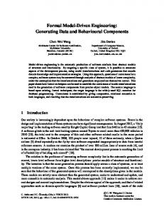
A. The ERTMS/ETCS System Architecture The main function of the railway signaling system is to assure the reliability of the communication between the grounds (the train control centers) and the on-board (train driver). This paper is dealing with the ERTMS/ETCS system. Its architecture is presented in figure 1.
In general, the onboard ERTMS/ETCS assembly is composed of: Balise Transmission Module (BTM) and Loop Transmission Module (LTM): manage messages between the train and the Eurobalise and the Euroloop respectively. Euroradio: applies the Euroradio Protocol to encode and decode the message sent by the RBC and decode the messages received from it. GSM-R: used for bi-directional exchange of data (or messages) via the GSM-R network. Jur. Recording: records data coming from the onboard ERTMS/ETCS. Kernel (or EVC): computer-based systems exchanges messages between the onboard sub-systems and the trackside. Main Machine Interface (MMI) or Driver Machine Interface (DMI): defines the interface between onboard equipment and the driver. Odometry: provides train location information (i.e. position, speed and driving direction). Train Interface Unit (TIU): used to allow the onboard ERTMS/ETCS assembly to interface with train systems. Besides, the trackside ERTMS/ETCS assembly is composed of: Eurobalise: transmission equipment installed in the track. It ensures the transmission of data to the onboard ERTM/ETCS when a train passes over it. Euroloop: allows the transmission of additional data. Lineside Electronic Unit (LEU): is a connection equipement used to join Eurobalises and Euroloops to the signalling system. It calculates the variable data coming from Eurobalise and transmitted to the train. Radio Infill Unit (RIU): used in ERTMS level 1. It sends additional data using radio channel. GSM-R Trackside radio: is used to ensure the message exchange between the onboard and the RBC. Radio Bloc Center (RBC): is a computer-based system which calculates the variable data to be sent to train via radio. Key Management Center (KMC): used to manage the configuration and the deployment of the cryptographic keys in order to ensure the communication between the onboard and trackside ERTMS/ETCS assemblies.
Fig. 1. ERTMS/ETCS system architecture.
B. ERTMS Levels The onboard ERTMS/ETCS assembly and the trackside ERTMS/ETCS assembly components are closely depending on the application of the ERTMS. In addition to the Specific Transmission Module Level (STML) and Level 0, three other levels have been specified [9].
ERTMS Level 0: the movement authority is given by the lineside signals. ERTMS STML : It is used to allow an ETCS equipped train to run on routes that are fitted with national train protection systems. In this level, the use of lineside signals depends on the implementation of the national train protection systems. Moreover, the level of supervision provided by STML is depending on the national protection system.(ERTMS/ETCS - Baseline 3). ERTMS Level 1: in this level, the Lineside Electronic Units receives data from the control and command center and transmit them to the on-board calculator via Eurobalises. Moreover, in ERTMS Level 1, the lineside signals are indispensable to indicate authority to move to the train driver (see Fig. 2). (ERTMS/ETCS - Baseline 3)
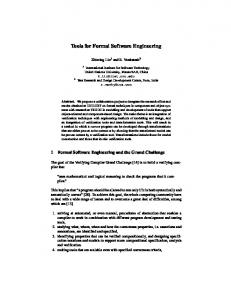
ERTMS Level 3: This Level is still under developing. It aims to use radio signals to control trains spacing. Trains use sensors (accelerometer, radar…etc) and eurobalises to locate, as in ERTMS level 2. Each defined position can be verified at any time by transmitting location message to control center. Thus, a movement authority can be transmitted to next trains.
Fig. 4. ERTMS/ETCS application level 3. C. ERTMS : Modes and Transitions The ERTMS specifications (ERTMS/ETCS - Baseline 3) define several train operation modes and mode transitions in order to ensure safety requirements compliance. As follows, some possible operation modes are briefly presented and then, an extract from the mode transition table is proposed and explained [10].
Fig. 2. ERTMS/ETCS application level 1.
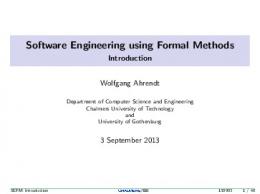
ERTMS Level 2: unlike Level 1, in this level, the movement authority is displayed on board. Controlling railways occupancy state and train integrity remain deployed on the ground while the external signal installations become useless. (ERTMS/ETCS - Baseline 3). Regular train reports are exchanged between the train and the Radio Bloc Center which allows the RBC to control permanently the train movement. Further, the EuroBalises are used to define the right train position and then to correct any possible measurement errors.
Full Supervision (FS): when all the train and track data, required for a complete supervision of the train, are available, the equipment maybe in FS mode. On Sight (OS): this mode enables the train to go into a track section while it is occupied by another train or obstructed by an obstacle. Shunting (SH): the aim of this mode is to enable shunting movements. Staff Responsible (SR): in this mode, the train is moved under the driver own responsibility in an ERTMS/ETCS equipped area. No Power (NP): the equipment is in No Power mode when the ERTMS/ETCS on-board equipment is not powered. Sleeping (SL): defined to manage the ERTMS/ETCS onboard equipment of a slave engine that is remote controlled. Stand By (SB): it is a default mode that cannot be selected by the driver. Trip (T): Exceeding the permitted speed leads to application of the emergency brakes, and the mode becomes a train trip when the train passes the End Of Authority (EOA).
Fig. 3. ERTMS/ETCS application level 2.
Post Trip (PT): this mode happened after the driver acknowledges the trip. Reversing (RV): This mode allows the driver to change the direction of movement of the train and to drive from
the same cab (i.e. the train orientation remains unchanged). These modes and the transitions between them are detailed in chapter 4 (Modes and Transitions) of the ERTMS/ETCS – Baseline [10]. Table I is an extract from the mode transition table which will be used in the following sections to explain the proposed approach. TABLE I. NP
< 29 -p2-
4> -p2-
SB
EXTRACT FROM THE MODE TRANSITION TABLE < 29 -p2< 28 -p5-
< 29 -p2< 28 -p4-
……. 15 > -p7-
OS ……. 59 > -p6-
RV
The transition from one mode to another is possible if and only if there is a condition of transition between the two modes. Nevertheless, if the table field is empty, there are no transitions between modes. For example, the transition from OS (On Sight) mode to the SB (Stand By) mode is allowed only if the condition number 28 is satisfied (see continuous arrow). Moreover, a condition priority is also defined (i.e. -p1- define the highest one) to select the suitable mode when several conditions are fulfilled [10]. III.
SYSTEMATIC GENERATION OF FINITE STATE MODES APPROACH
A. Formalization of a Mode Partition and Conditions The formalization problem, presented in this subsection, consists in the splitting the mode transition table into modes and transitions. A mode partition is denoted as P = (M , Ctrans), where M is a vector of |M| elements (e.g. each element is a mode) and Ctrans is a |M| x |M|-matrix (e.g. defining the presence of transitions between modes). For confidential reasons, only modes and transitions of table I will be considered will be considered, and used throughout this paper to illustrate the proposed approach. Based on this table and the mode partition, the transition between modes should be described using the matrix Ctrans where Ctrans(i,j) = 1 if there is a transition between mode Mi and mode Mj. For example, there exists a transition between the mode M2 = SB and mode M3 = OS and this can be seen in the matrix Ctrans, because Ctrans(2,3) = 1. However, there is no transitions between the mode M1 = NP and the mode M3 = OS and this can be seen in the matrix Ctrans because Ctrans(1,3) = 0.
It is important to notice that Ctrans is not a symmetrical matrix because the mode transition table is not symmetrical. Moreover, all the diagonal elements of the matrix Ctrans are fixed to 1, which means that each selected mode has to still the same if there is no new fulfilled condition. NP SB M OS RV
1 1 Ctrans 1 1
1 0 0 1 1 0 1 1 1 1 0 1
The system ability to detect a transition from one mode to another in the mode partition P is defined by: A = (Cnd, M, Tmode) where Cnd is a vector of |Cnd| elements (each element is a condition of a transition from one mode to another) and Tmode is a |Cnd| x |M|- matrix (representing the different conditions of transition from each mode to the others). M is described above, while Cnd and Tmode of the proposed case study are given below. There are five different conditions of mode transitions creating the vector Cnd. The transition condition matrix is represented by matrix Tmode, where Tmode(i,j) = 1 if the condition Cndi allow the transition to the mode Mj. For example, the condition Cnd1 = 29 allows the transition to mode M1 = NP. Besides, the transition to the mode M2 = SB, can be reached if one of the two conditions: Cnd2 = 28 or Cnd3 = 4 is fulfilled.
29 28 Cnd 4 15 59
1 0 Tmode 0 0 0
0 0 0 1 0 0 1 0 0 0 1 0 0 0 1
B. Algorithm for systematic generation of finite state modes Once the partition of the mode transition tables in modes and in transition is realized, a finite automaton representing the detectable mode transition can be built. This automaton is called Transition Modes Automaton (TMA) and denoted as TMA = (S, N, Ω, S0) where: S is a set of states (modes), N a numerical parameter related to the condition of mode transition, Ω a transition function and S0 a set of initial states. Algorithm 1 is proposed to generate the TMA (see Fig. 5). After defining the required data and then the set of states’ S in line 3, each state is considered to be an initial state of the automaton (line 4). This assumption is due to the fact that the automaton can be started at any defined train mode. Then, from line 6 to line 8, the conditions of transitions are created. Finally, the transitions between states are defined (line 9 to 13).
Algorithm 1: Generation of TMA Data: M, Ctrans, Cnd, Tmode 1. TMA ← (S, N, Ω, S0) 2. for i from 1 to |M| do 3. create state si = Mi in S 4. set state si in S0 5. end for 6. for j from 1 to |Cnd| do 7. create Cndj in N 8. end for 9. for (i, k, j) from (1, 1, 1) to (|M|, |M|, |Cnd|) do 10. if (Tmode(j,k) = 1) and (Ctrans(i,k) = 1) then 11. define Ω(si,Cndj) = sj 12. end if 13. end for 14. result : generate TMA Figure 5 illustrates the TMA of the example of table I.
Fig. 5. Example of TMA.
useful for the dynamic train operation mode tracking. In fact, it is possible to estimate a new system mode state by finding the equivalent deterministic automaton [11]. An algorithm (Algorithm 2) is proposed in this subsection to find the dynamic train operation mode tracking. In others words, it is applied to dynamically verify that a scenario maps to the ERTMS rules. The input data of this algorithm is the finite automaton obtained by algorithm 2, and denoted by TMA = (S, N, Ω, S0); where: S is a subset of S, N a numerical parameter related to the condition of mode transition, Ω a deterministic transition function and S0 the initial state. Algorithm 2 starts by the initialization of the current train mode Mc. Then, when an event happen and a new condition of mode transition is detected Cnd, the consistency of the transition function is checked. If the transition function is respected, the current mode is updated or remains the same otherwise Algorithm 2: Train Operation Mode Identification Data: TMA ← (S, N, Ω, S0) 1. initialization: current mode Mc = S0. 2. while mode tracking is active do 3. wait for a condition of mode transition 4. new condition is detected Cnd 5. if (transition function is respected: Ω(Mc, Cnd)) then 6. update curent mode Mc = Ω(Mc, Cnd) 7. else 8. the current mode remains the same 9. end if 10. end while The TMA of the case study of table I is reported in figure 6.
This algorithm is proposed here to not estimate the new mode state but to check the transition between train modes which is considered crucial to ensure system safety. Moreover, it is worth noting, that in this considered new approach only the conditions of transitions are considered while priorities between them are not taken into account. Besides, this algorithm is a static state estimation of the Transition Modes Automaton. Nevertheless, during a train move several modes can be allowed. For all of these reasons, a second algorithm (Algorithm 2) is proposed to describe the dynamic train operation mode. IV.
TRAIN OPERATION MODE TRACKING ALGORITHM
A. Algorithm for Dynamic Train Operation Mode Tracking Each generated TMA defines a static state estimation of the train mode. Nevertheless, all the generated TMA are very
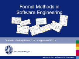
Fig. 6. Finite automaton for the identification of train operations modes. B. Real Scenario Application A scenario example, extracted from the mode transition table of the (ERTMS/ETCS - Baseline 3) and presented in table I, is illustrated in this subsection to show the practical use of the proposed algorithm 2.
Our current work is devoted to extend the proposed approach by considering priorities between train transition modes.
The considered scenario can be not feasible in reality but for confidential reasons, it is used to illustrate the algorithm steps. This scenario is as follows: the train is allowed to go into a track section while it is occupied by another train or obstructed by an obstacle, so the On Sight (OS) mode is active as initial mode state (the current one). Then, a new event happens and the train driver is allowed to change the direction of movement of the train and drive from the same cab. Thus, the new train mode becomes Reversing (RV). Finally, the train run on default mode: Stand By (SB) before moving to the No Power (NP) mode.
ACKNOWLEDGMENT This research was supported in part by the engineering school “Ecole Centrale de Lille (EC-Lille)” under a grant from the ANR Research Project, named “Performing Enhanced Railway Formal Engineering Constraints Traceability (PERFECT)”.
By applying algorithm 2 to the considered scenario example, the following system states can be displayed (see Fig. 6):
REFERENCES
State 1
[1]
P. Sun, S. Collart-Dutilleul, and P. Bon, “Formal modelling methodology of French Railway Interlocking System via HCPN,”. Transport Research Arena (TRA 2014), Paris, 2014. [2] S. Qiu, “Graphical models for RAMS assessment and risk analysis of systems of systems under uncertainty,” PhD, Compiègne University of Technology, December 2014. [3] S. Qiu, M. Sallak, W. Schön, and Z. Cherfi-Boulanger, “Modeling of ERTMS level 2 as an SoS and Evaluation of its Dependability Parameters Using Statecharts,” Accepted by IEEE Systems Journal, 2014. [4] S. Qiu, M. Sallak, W. Schön, and Z. Cherfi-Boulanger, “Availability assessment of railway signaling systems with uncertainty analysis using Statecharts,” Simulation Modelling Practice and Theory, vol. 47, pp. 118, 2014. [5] S. Qiu, R. Sacile, M. Sallak, and W. Schön, “On the application of Valuation-Based Systems in the assessment of the probability bounds of Hazardous Material transportation accidents occurence,” Safety Science, vol. 72, pp. 83-96, 2015. [6] R. Ben Ayed, S. Collart-Dutilleul, P. Bon, A. Idani, A, and Y. Ledru, “B Formal Validation of ERTMS/ETCS Railway Operating Rules,” Y. Ait Ameur and K.-D. Schewe (Eds.) : ABZ 2014. LNCS, vol. 8477, pp. 124129. Springer, Heidelberg, 2014. [7] R. Ben Ayed, P. BON,and S. Collart-Dutilleul, “Checking the European Railways Traffic Management System (ERTMS) operating rules using UML and B method”,14th International conference on Railway Engineering Design and Optimization, Italy, pp.139-149, June 2014. [8] A. El Amraoui, and K. Mesghouni, “Colored Petri Net Model for Discrete System Communication Management on the European Rail Traffic Management System (ERTMS) Level 2”, 16th International Conference on Modelling and Simulation (IEEE-UKSim 14), Canbridge, UK, (26-28 March 2014). [9] ERTMS/ETCS - Baseline 3. (2008). System Requirements Specification. Chapter 3, Principles. Subset-026-3, Issue 3.0.0. 23, Decembre 2008. [10] ERTMS/ETCS - Baseline 3. (2008). System Requirements Specification. Chapter 4, Modes and Transitions. Subset-026-4, Issue 3.0.0. 23, Decembre 2008. [11] C. Cassandras, and S. Lafortune, “Introduction to Discrete Event Systems,” springer-verlag ed., 2009.
The initial mode is initialized. The initial current mode is the initial state mode of TMA which is Mc = (NP, SB, OS, RV). In this step, the general case is considered where it is assumed that the initial mode is unknown. State 2 An event happen and a condition of transition is received (Cnd4 =15). So, the current mode is updated and it becomes Mc = OS. State 3 Then, the condition (Cnd5 =59) is received, the current mode is updated and becomes Mc = RV. State 4 After that, a new condition is received (Cnd2 =28), so the current mode is updated to Mc = SB. State 5 Finally, the ERTMS/ETCS on-board equipment is allowed to be switched off. So the condition (Cnd1 =29) is received, the current mode is updated and becomes Mc = NP. V.
CONCLUSION
In this paper, a new state model approach to check and validate mode transitions of the ERTMS level 2 specifications is proposed. A scenario mode transition example is used to illustrate the steps of the train operation mode identification algorithm and to validate it.
**