ofthe 0.193 jim-length. 0. 0. 4. 8. 12. 16 .... J. P. Dowling , M. Scalora, M. J. Bloemer, and C. M. Bowden, "The photonic band edge laser: a new approach to gain.
Photonic bandgap structures with n-i-p-i layers Andrey G. Smirnov*, Dmitrij V. Ushakov, Valerii K. Kononenko
Stepanov Inst. of Physics, National Academy of Sciences of Belarus Fr. Scorina Pr., 70, 220072 Minsk, Belarus
ABSTRACT Optical properties of one-dimensional heterostructures having optical forbidden gap are described and photonic structures with n-i-p-i superlattices are designed for laser applications. Keywords : bandgap material, n-i-p-i superlattice, laser microcavity, asymmetric photonic structure
1. INTRODUCTION At present, bandgap structures with a period closed to an optical wavelength arouse increasing interest. In particular, the photonic bandgap (PBG) structures seem promising for providing the increase of optical nonlinear response of a material in order to attain high efficiency of nonlinear processes at rather small length. Based on photonic crystals, different novel
compact optical devices can be realized, including optical switches, single-mode lasers and amplifiers, light pulse compressors and frequency converters. In the present work, we make an attempt to combine wide possibilities in controlling optical properties of doping semiconductor superlattices, e.g., dispersion, luminescence, absorption, and amplification spectra, together with the unique feature of a bandgap material to concentrate electromagnetic energy in time and space. Doping superlattices, or n—i-—p—-i crystals, belong to peculiar artificial tunable low-dimensional systems.' Optical and electric properties of the superlattices can be varied in a wide range under excitation and through the choice of the thickness and doping of the crystal layers.' Their main features are (a) spatial separation of electrons and holes in different remote quantum wells, (b) tunable energy bandgap under optical or electric excitation, (c) enhanced current carrier lifetime and lowed oscillator strength of optical transitions, (d) strong modification ofthe energy level structure depending on the doping impurities distribution and concentration, and (e) wide variation ofthe properties and characteristics due to design parameters or introducing the additional quantum wells and 6-doped regions. Based on these unique tunable properties of the doping superlattices, different compact photonic structures with n-i-p-i layers can be designed for laser applications.
2. DESIGNING THE PHOTONIC STRUCTURES WITH n-i-p-i SUPERLATTICES Recently,4 it was shown that structural optimization of a bandgap material on the grounds of the analysis of boundary conditions and mechanisms of energy localization results in the dramatic enhancement ofthe material nonlinear response. In some cases, it will lead to unusual features in the optical device performance. Combining the doping superlattices with a bandgap structure opens new possibilities to take advantage of flexible control of their nonlinear optical properties6' and to offer better design of photonic elements in order to get maximum performance efficiency.
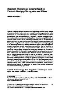
We consider one-dimensional layered bandgap structures consisted of different homogeneous layers (Fig. I ). Each layer is characterized by thickness d and complex, in general case, refractive index n(?) =nr(X) + ik(2) being a function of light wavelength ?. Light is assumed to propagate perpendicularly to the interfaces of layers. Some layers are active, i. e., made from n-i-p-i superlattices. They are controllable and their optical properties are modified due to electric or optical excitation. The refractive index of n-i-p-i layers depends on light wavelength and the difference in the quasi-Fermi levels AF. The model is considered where a pump excites uniformly the whole structure, hence AF is the same within all active layers. One of the possible way to get optical stop band is to create some sort of quasi-periodic arrangement of layers. Now, we intend to introduce a specific notation for encoding various types of layered, in particular, periodic structures. Let us denote by a character an unique layer having a certain material type and thickness. Enclosing set ofthe characters in brackets defines an elementary cell that may be replicated in order to form a periodic arrangement of a bandgap material. For example, entry "/4B]40" corresponds to a two-component generic periodic stack composed from 40 pairs. By defining original composition and multiplication rules we can write equivalents, i. e., "(AB]40=[IABJ20)2=[ABJ20IAB]20". *
E-mail: andr)dragon.bas-net.by: phone: 375 017 284-2595; fax: 375 017 284-0879; http://ifanbel.bas-net.by/
70
Saratov Fall Meeting 2001: Laser Physics and Photonics, Spectroscopy, and Molecular Modeling II, Vladimir L. Derbov, Leonid A. Melnikov, Lev M. Babkov, Editors, Proceedings of SPIE Vol. 4706 (2002) © 2002 SPIE · 0277-786X/02/$15.00
GaAs
(n-i-p-i) Ga051In0,49P
Light
Ji'i] []\[1 H. Figure 1 : One-dimensional PBG structure with the GaAs n-i-p-i crystal active layers.
In our study, we seek for transmission and reflection properties of photonic heterostructures as well as light pattern inside the structure. This help us to achieve better matching ofelectromagnetic filed within the active layers to get maximum optical effect. We use transfer matrix method which is the best tool to calculate all necessary parameters, i. e., the transmission T and reflection R coefficients and distribution ofmodulus ofelectric amplitude El vs. the z-coordinate.
For constructing a composite bandgap material, we suggest heterostructures in the GaAs-GaIn1.P system, which are lattice-matched to the GaAs substrate. Superlattice layers are made as the GaAs n-i-p-i crystals with s-doped n- and p-layers of 2.8 nm-thickness and with i-layers of 6.8 or 1 1 .3 nm-thickness. Depending on the impurity concentrations and layer thickness, the effective band gap of the doping superlattice changes from 0.04 to 0.53 eV under optical or electric excitation. Accordingly, the refractive index and gain spectra are varied in a wide range (see Figs. 2 a and 3). We have emanated from an opportunity of the growth of the bandgap structures in the GaAs-GaIn1P system considering sizes of lattice constants and lattice matching. Therefore, thickness of the GaAs n-i-p-i layers is adjusted to the lattice constant of 0.565 nm and the GaIn1P layers make up is considered to have the mole fracture x = 0.5 1, i. e., the wide-band material is Ga051tn049P the forbidden gap ofwhich is 1.89 eV.
3. PHOTONIC HETEROSTRUCTURES FOR SWITCHING AND FILTERING Structures with a tunable PBG material is attractive as optical switches.8 The availability of n-i-p-i crystal layers in such periodic structures has been considered for the GaAs-A1GaAs system.7 We offer the following parameters of the generic {ABJN stack. LayerA is the n-i-p-i superlattice with n-doped andp-doped layers ofthe thickness d= d= 2.83 nm, i-layers of the thickness d, = I I .3 1 nm and the concentrations of donors and acceptors ofNd =Na 5.3x10'9 cm3. The total length of the superlattice equals 1 1 3 nm and covers four periods. The surface concentration of impurities is 1 .5x 1013 cm2 and the effective bandgap ofthe superlattice falls up to Eg= 0.04 eV. Layer Bis the wide-gap semiconductor component, i. e., the Ga0 51In049P layer with the thickness of I 16 nni.
In such type structures the PBG coincides with the wavelength near 1 .5 pm which is attractive for optical networks. The main feature ofthe switches is the control ofthe PBG edge near 1.5 m by light at a shorter wavelength due to the change in the refractive index of the active layers. In doping superlattices the dependence of the refractive index at a fixed wavelength on the quasi-Fermi level difference AF is nonmonotonous6 (Fig. 2 a). Therefore, the transmission spectrum of the considered periodic structure is tunable.
The refractive index of the active layers includes the refractive index of the host material and the quantizied addition An(AF) originating with the doping superlattice which depends on the excitation level. As it follows from Fig. 2 a, the variation of An does not exceed 0.006 for any value of AF. Hence, we can not expect large variation of the central Bragg wavelength ABragg An. Nevertheless, the variation in the transmission ofthe whole structure appears to be significant if one operates in the vicinity of such called 'transmission resonances",4' 8 or "defect mode".9 Since the latter seems more sensitive vs. An, we propose on the basis of our generic stack a modified structure with a "defect" layer exhibiting the transmission band ("defect or impurity mode") near the 1 .53 tim, i. e., {AB]54[AB]50. In Fig. 2 b, the transmission spectra of [AB}54{AB]50 for different quasi-Fermi levels difference AF = 0.4 eV (solid line) and I .49 eV (dotted line) are presented. Under excitation of the active n-i-p-i layers, the defect mode is shifted to the long-
wavelength side because of increasing the refractive index of the layers (Fig. 2 a). The quantity of the "red" shift is determined by the distribution of the quasi-Fermi level difference in the layers along the photonic structure and depends on the wavelength of controlling light.7 At the higher levels of excitation of the structure the defect mode has to be shifted to the back direction ("blue" shift) because of the decreasing of the refractive index of the doping superlattice. For PBG edge such a
Proc. SPIE Vol. 4706
71
shift was described for the GaAs-AIGaAs system.7 The shift of the defect mode is more sensitive and reaches the value of 2 nm. This effect can be used for the stabilization of operating wavelength.
T
An
0.052 0.050
0.25 0.50 075 1.00 1.25 4F(eV)
(a)
(b)
Figure 2: (a) Quantizied adding to the refractive index ofthe doping superlattice An at the wavelength of I .53 im vs. the quasi-Fermi
levels difference AF and (b) the transmission spectrum T() ofthe [AB]5,A(AB]50 PBG structure at different excitation levels.
4. LASING IN PHOTONICS HETEROSTRUCTURES Here, we study lasing properties of semiconductor superlattices embedded into a PBG material. The motivation comes from the results of recent investigation4 on bandgap structures demonstrating that the dramatic enhancement of optical gain can be attained under proper arrangement of composite crystal geometry despite the fact that the amplification per single active layer is not very As a possible candidate for lasing medium, n-i-p-i superlattices seem to be the best ones. They are feasible for integrating in optical circuits and, moreover, one can fabricate a superlattice in a desirable manner to provide appropriate dispersion and emission properties in a wide spectral range. We would like to introduce several new geometries of bandgap microcavities applied for creation of low-threshold supercompact lasers operating at multiple wavelengths. Such microcavities are attractive for WDM technologies.
For our generic periodic stack (ABIN we propose the following materials. Layer A is the GaAs n-i-p-i superlattice. For distinctness, we choose the same set ofparameters used for the n-i-p-i material in section 3. As it can be seen from Fig. 3, at the proper level of excitation (AF > 1 .4 eV) the imaginary part k of the n-i-p-i layers refractive index becomes negative resulting in light amplification within certain spectral range ('-0.9 tm). Layer B is the wide-gap semiconductor component Ga0.5 11n049P. In this type of PBG structures Ga0.511n049P layers have the thickness of 16 tim that shifts the PBG to the 0.9 rim-
region.
0.01
E 0.00
900
1200 Wavelength, nm
1050
1350
1500
Figure 3: Imaginary part of the n-i-p-i layer refractive index vs. the excitation level zIF.
72
Proc. SPIE Vol. 4706
Again we consider the model where a pump excites uniformly the whole structure and tiE remains constant within all active layers. For simplicity, it is also assumed that photonic heterostructure is grown on the infinite GaAs substrate. In other
words no additional reflection occurs at end faces of the PBG crystal. Various schemes are possible, for example, antireflection coatings or Brewster-angle polishing to make the last condition true.
We study the optical gain in PBG structure with active n-i-p-i superlattice in the frame of linear approximation, i. e., the amplification coefficient ofthe active layers does not depend on light intensity at lasing wavelength. The questions we try to answer are what kind of lasing modes a certain bandgap structures may exhibit and what is the lasing threshold. In order to determine lasing wavelengths ?, and threshold kIhr(2m) one calculates the transmission coefficient TQ, k) of PBG structure and finds out at what ? and k it turns to infinity. This rigorous method is hardly resolved analytically for asymmetric PBG structures with no translational symmetry and for structures containing materials with complex dispersion properties (such as semiconductor superlattices). Hence, some numerical algorithm has to be involved. In our recent investigation5 we performed such type of calculations based on transfer matrix technique for generic periodic stack (AB]N. It was shown that generation occurs at a number of wavelengths coinciding with the structure "transmission resonances'. Thus, a set of modes is discrete and depends on number of periods in the stack. Also the strong discrimination of modes was predicted, i. e., the threshold k,hr(2n,) significantly increases with the order m of a resonance. In fact there are two almost equivalent lasing modes ofO-th order with minimum klhr corresponding to the edges ofan optical stop band.
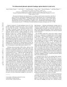
The last result was predicted in Ref. 4 and is explained due to strong delay of the group velocity V that increases optical path in active material. One describes such phenomenon in terms ofelectromagnetic modes density (DOM), p = V1 = dK/dn, which is the reciprocal group velocity. Maximum value of p corresponds to the maximum of JfE(z)I2dzinside the structure. Therefore, the quantity p is suitable for the description oflight localization in a PBG material resulting in the increase of light amplitude E(:)I. In Fig. 4, we plot DOM vs. light wavelength for various types of PBG materials with active n-i-p-i layers. For the calculation of DOM of the finite one-dimensional (1D) PBG structures the approach described in Ref. I 0 was used. As it is seen from the figures, maximum ofDOM is accompanied with the strong enhancement ofthe transmission coefficient Tthat evidently indicates on the existence of lasing mode. The direct calculation of T shows that at a certain value ofthe gain the lasing threshold is attained and transmission Tturns to infinity. Let us discuss in more details various types of structures presented. In general, three factors may be outlined influencing on high efficiency of amplification at various types of lasing modes: (a) maximum of DOM, (b) strong overlapping of light pattern IE(z) with active layers, and (c) high values of gain of active layers at a specified operating wavelength (see Fig. 3). We start with generic stack (AB]140 (Fig. 4 a) possessing two basic transmission resonance modes at the forbidden gap edges. Although both modes have a negligible difference of DOM calculated for passive structure, in the case of PBG material with active n-i-p-i superlattices the "red" mode (950 nm) are more effective than the "blue" one (933 urn). This is despite of the fact that gain k at 950 nm is lower than at 933 nm. The reasonable explanation is the more strong overlapping of light pattern with active layers for the "red" edge ofthe stop band.4 Fig. 4 b depicts the results concerning symmetric "defect" structure {AB]5,D(AB]5,. The defect is the Ga51In049P layer with the 0.07 tim-thickness. It is well known that such structure exhibits strong light localization in the vicinity of the defect layer.9 The calculated value of DOM for the "defect" mode is much higher than correspondent values of transmission resonance modes obtained for the generic stack at fixed overall length of the structure. As it was for the first time reported,9 the result is the stronger spatial localization (see inserts in Fig. 4) and hence the order of magnitude smaller threshold for a defect mode in comparison to transmission resonance one.
On the basis of two types of structures discussed above we propose novel types of 1 D microresonators which are attractive for simultaneous lasing at multiple wavelengths. These are systems of coupled microcavities and {[AB)4,D)2[AB)45 (Fig. 4 c, d). The new feature of such structures is coupling of two localized states that causes the splitting of a central defect mode in two modes — the effect similar to the appropriate one in solid state physics." Also in the [(AB)3,D(AB]3]2 structure we observed new type of transmission resonant modes corresponding to large values of DOM. The excitement of such type of modes (they are marked with an arrow in Fig. 4 c) results in the strong confinement of light at a central part ofthe microcavity between two defect layers.
In Figs. 5 and 6, the possibility of lasing at different wavelengths with opposite output directions is demonstrated. Two types of structures are proposed. The resonator of type I (Fig. 5) is composed from a generic periodic stack (area I) and symmetric "defect" structure (area II) emitting at different lasing modes as it was mentioned above. One realizes switching between these modes by pumping of different parts of the microstructure, i. e., either area I or II. Additionally, the lasing at different wavelengths occurs in the counter directions since area I (II) functionates as almost 100 % mirror for area 11(1) operating wavelength.
Proc. SPIE Vol. 4706
73
In type II resonator (structure of coupled microcavities similar to the described one in Fig. 4 d) lasing is performed simultaneously at two separate wavelengths X and X2 and in opposite directions as well. The solution is possible owing to additional selective Bragg mirrors blocking the light output at the resonator end faces (Fig. 6). The blocking Bragg mirrors can be constructed in the GaAs-GaIn1P system. We offer the following design: [Gc]4o([AB]3,D(AB]3f,D(ABJ35](GC]4o, where "G" is the GaAS layer ofthe 0.209 rim-thickness, C' is the 0.188 tm-Ga51In049P layer, and "c' is the Ga051In049P cell ofthe 0.193 jim-length. 60.0 -
50.0 16
a)
b)
12
U)
Cl)
: 40.0 -
e8 40.0-
.0 (1
4
'I,
- 30.0 -
0
0 8
4
i
20
16
12
i
i
,
4
8
12
16
Length, microns
C
Length, microns
0 (I)
U) 20.0 -
E 20.0'I)
E (I)
{AB}140
{AB}55D{AB}55
C
c I-
C F-
T
10.0 -
DOM
0.0 -
— —d-
0.0 —
I
940
960 Wavelength, nm
25.0 —
980
1000
920
940
'
I
120.0 -
12
DOM
•
'
I
980
960 Wavelength, nm
1000
25
C)
20
00 . 20.0 —
0 15
U)
C
C
10
. 80.0-
.0
0
,
0
15.0—
0 0
4
8
12
16
20
Length, microns
oO
00
0
4
8
12
16
Length, microns
o$
C
0 {{AB}35D{AB}35}2
I F- so0.0 -
C/)
40.0-
......,...,. —.— T
!
DOM
LA4 I
940
'
{{AB}45D}}2{AB}45
-÷
....V.V.V....
DOM
'
960 Wavelength, nm
•
I
I
980
1000
0.0 920
I
,
940
I
960 Wavelength, nm
980
1000
Figure 4: DOM and the transmission T of different types of PBG structures with active n-i-p-i layers (AF = 1.42 eV). The inserts depict light pattern E(z) inside the structure at the wavelength marked by the arrow.
74
Proc. SPIE Vol. 4706
20.0 -
100.0 —
a) 16.0
b)
-
80.0 —
C
0
0 0
C.)
a)
12.0
11)
-
ci)
C
10
15
20
25
Length, microns
0 Cl)
E
05
C
0
8.0 -
•Cl)
60.0 —
ci)
5
(I)
40.0 -
Cl)
{{aB}50D{aB}50}{AB}120
Cl)
E
C
10
15
20
25
Length, microns
{{AB}50D{AB}50}{aB}120
Cl)
C
Co
4.0
-
0.0
R
I
'
I
0.0 —
940
930
920
R
20.0 —
'
I
950
930
920
Wavelength, nm
940
950
Wavelength, nm
Figure 5: Two lasing modes oftype I PBG structure, (a) "transmission resonance mode", (aB)5D[aBJ50(ABJ120, (b) "defect mode". (AB)5D(ABJ5O(aBJI2O. Active n-i-p-i layers are denoted by character "A" (AF 1.4 eV); passive n-i-p-i layers - by character "a" (AF = 0). Switching between the wavelengths and directions oflasing is realized under the pump of different areas ofthe structure. The inserts depict light pattern E(z)I at the operating wavelength and the distribution of the imaginary part of the refractive index Jm(n(z))x103.
40
500.0 Mirror 2., - {{AB}35D(AB}5D{AB}35} - Mirror ?
x, - mode
?, - mode
400.0 -
Cl a)
30 -
300.0 -
20 -
no
0 E
m
200.0 -
LU
10-
C
T
100.0 -
0-
0-
JAL 920 Wavelength,
924
nm
928
0 5 10 15 20 25 30 35 40 45 50 Length, microns
)
lllIllIili I
5 10 15 20 25 30 35 40 45 50 Length, microns
Figure 6: Two lasing modes of type II PBG structure Bragg Mirror 1-[ABJ35DABJ3,D1ABJ35J-Bragg Mirror ?2 (AF and forward at ?2. occurs simultaneously at opposite directions, backward at
1.42 eV). Lasing
Proc. SPIE Vol. 4706
75
CONCLUSION In the present work, we have studied the optical properties of n-i-p-i superlattices embedded into 1D bandgap material. Transmission and reflection spectra as well as the distribution of the field intensity inside the PBG material are investigated. The feasibility of the n-i-p-i heterostructures is shown for optical switching and laser applications. New types of laser microcavities are proposed providing low-threshold lasing at multiple wavelengths and opposite directions. The integrated assembly of such microresonators pumped either by electric current or optical radiation seems promising for WDM technology.
ACKNOWLEDGMENTS This work was granted by the Belarussian Republican Foundation for Fundamental Research and Russian Foundation for Basic Research underjoint Project No. F99R-119/620.
REFERENCES 1.
G. H. Döhler, "Doping superlattices ("n-i-p-i crystals")," IEEE. I. Quantum Electron. QE-22, pp. 1682-1694, 1986.
2. V. K. Kononenko, I. S. Manak, and D. V. Ushakov, "Optoelectronic properties and characteristics of doping superlattices," Proc. SPIE 3580, pp. 10-27, 1998. 3. V. K. Kononenko and D. V. Ushakov, "Functional optoelectronic properties ofn-i-p-i superlattices and structures," Proc. 3rd mt Conf on Transparent Optical Networks, pp. 64-67, Cracow, 2001. 4. J. P. Dowling , M. Scalora, M. J. Bloemer, and C. M. Bowden, "The photonic band edge laser: a new approach to gain enhancement," J. Appl. Phys. 75, pp. 1896-1994, 1994. 5. A. G. Smirnov, "Effects of spatio-temporal concentration of light energy in confined one-dimensional photonic crystals," PhD Thesis, Stepanov Inst. ofPhysics NASB, Minsk, 2001. 6. D. V. Ushakov, V. K. Kononenko, and I. S. Manak, "Nonlinear optical processes in doping semiconductor superlattices," J. Appi. Spectrosc. 68, pp. 501-505, 2001. 7. V. K. Kononenko, D. V. Ushakov, 1. S. Nefedov, V. N. Gusyatnikov, and Yu. A. Morozov, "Control of transmission in
photonic structures with n-i-p-i layers,"Proc. 3'' mt. Workshop on Laser and Fiber-Optical Networks Modeling, pp. 97-99, Kharkiv, 2001.
8. J. P. Dowling, M. Scalora, C. M. Bowden, and M. J. Bloemer, "Optical limiting and switching of ultrashort pulses in nonlinear photonic band gap materials," Phys. Rev. Lett. 73, pp. 1368—1371, 1994.
9. Y. C. Tsai, K. W. Shumg, and S. C. Gou, "Impurity modes in one-dimensional photonic crystals-analytic approach," J. Mod. 10.
Opt. 45, pp. 2147-2157, 1998.
J. M. Bendickson, J. P. Dowling, and M. Scalora, "Analytic expressions for the electromagnetic mode density in finite, one-dimensional, photonic band-gap structures," Phys. Rev. E 53, pp. 4107-4121, 1996.
11. M. Bayindir, S. Tanriseven, and E. Ozbay, "Propagation of light through localized coupled-cavity modes in onedimensional photonic band-gap structures," Appl. Phys. A 72, pp. 117—119, 2001.
76
Proc. SPIE Vol. 4706