Thank you for choosing the 2132 or 2116 Temperature Controller. Supplied in 1/
32 ... accurate, stable control of ovens, chillers, sterilisers and other heating and ...
design-type, i.e. all controllers are designed simultaneously. ... to assess robust stability and nominal performance in decentralized systems are surveyed.
by carrying PID tuning rules over to the fuzzy domain. .... V\VWHP FI )LJ 1 WKHUHIRUH WKH FRQWUROOHU PXVW FRQWDLQ DQ LQWHJUDWRU 7KH.
Page 2 ... 0°C, with a r coefficient of 0,00385 Ω according to the DIN-43760 ... and
assembling; the TC can measure higher temperatures than the double of RTD. ...
The correct tuning of the PID parameters (proportional band, integral, .... Ad
esem
about P, P-D, P-I and P-I-D controllers, their digital versus continuous time realizations and ... they can be implemented on real life projects. It was first intended ...
Oct 12, 2004 - PID controller, local linear model, self-organizing maps, Gaussian mixture. ..... Response of the closed loop nonlinear PID control system to ...
Description. Application focus. Standard number of sensor inputs. (optional).
Nominal low temperature capability. (with appropriate sensor). Simple Dew.
2 i 90-260Vac or 10-32Vac/dc DTC410 Temperature Controllers The Tempatron DTC410 series LCD digital temperature controllers are designed for simple on/off control of ...
0 te(t)2dt. ISTE : â«. â. 0 t2e(t)2dt. These criteria, however, are not suitable for multivariable processes, since each criterion is de- fined for a single-loop process.
Preprogrammed temperature controllers have an internal program chip which is
installed in the ... Power Requirements 110v/240v 110V/240V. Number of Fixed ...
E5CS. Easy Setting Using DIP Switch and Simple. Functions in DIN 48×48 mm-
size. Plug-in Temperature Controllers. • Easy setting using DIP and rotary ...
Listing 1 shows how to code this algorithm in C. We assume ... As a result, most
commercial PID controllers have functions to tune the 3 ... Automatic Tuning.
main idea of the proposed method is based on Tan's (et al.) technique for ... stabilizing PI controllers for interval plants is presented in âRobust stabilization using.
Tuning methods of PID parameters are classified as traditional and artificial intelligence (AI) methods. Conventional methods such as Ziegler-Nichols method do ...
the effect of sampling time and the choice of s*-domain to z-domain transformation method ..... usually provide the best results, it only provides optimal results.
extensive operator involvement, a temperature control system relies upon a ...
The controller is one part of the entire control system, and the whole system ...
104 DIGITAL METERS www.factorymation.com/digitalmeters To Order Call 1.800.972.0436 or Visit factorymation.com Part Number Price Description Size
May 2, 1995 ... improved system performance can be well worth the effort. ... systems. Optimized
temperature control will reduce temperature instability due to.
1. Preface. E5CC/E5EC Digital Temperature Controllers User's Manual (H174).
Preface. The E5CC and E5EC are Digital Controllers. The main functions and ...
KeywordsâPID controller, tuning, combustion, controller agents ... Dept. of Instrumentation and Control Engineering, [email protected] field was controlled ...
Cohen-Coon (1953) ... Often, in the PID-tuning literature very simple models are ... PID tuning literature, and is often called the FOLPD model (First Order Lag ...
couple RTD, or analog signal, and maintains a setpoint using an output signal.
Temperature controllers are powerful control tools, but offer very simple operation
...
Communication. Power Supply. Specifications are subject to change without
notice. 1. PID Controllers. Temperature Controls. T2000. Input Specifications (
cont'd).
1/16 DIN and 1/32 DIN NEMA 4X protection Autotune automatically sets PID parameters Single ramp/soak program Heat-cool operation AC or DC power supply Inputs: Thermocouple, RTD, 0-50mV Two outputs: SSR voltage pulse/relay Five alarm modes RS232 or RS485 (retrofittable) MODBUS RTU protocol Three year warranty
Product Description
Ordering Key
Microprocessor based controller for temperature measurements in °C or °F. Easy to view single or dual 4 digit display readout. Constructed in a rugged NEMA4X waterproof housing in the popular 1/32 or 1/16 DIN size. 100-240VAC or 12-24VDC supply voltage. Universal inputs and various combinations of output types are also standard features.
Model Size Display Outputs Communication Power Supply
T20 16 1 SR 2 A
Type Selection Model
Size
Display
Outputs
Communication
Power Supply
T20
16: 1/16 DIN 32: 1/32 DIN
1:
SR: 5VDC Pulse and 1A Relay Outputs RR: 2A and 1A Relay Output SS: Two 5VDC Pulse Outputs
X: None 2: RS232 4: RS485
A: 100-240VAC B: 12-24VAC/DC (Only single display units with SR and SS outputs)
2:
Single Display Dual Display (1/16 DIN only)
General Specifications
Input Specifications
Power supply
Thermocouple (cont’d) S T Standards CJC rejection External resistance (RTD) Pt100/RTD-2 (2 wire) Standards
100-240VAC +/- 10%, 50-60Hz 12-24VAC/DC +/- 20%, 50-60Hz 4 digit high brightness green LED 10mm high 4 digit high brightness red LED 9mm high LED output indicators – flashing SP1 square green LED output indicators – SP2 round red 3 full travel elastomeric pushbuttons UL, CE
Input Specifications Thermocouple B E J K L N R
32 to 3275°F (0 to 1800°C) 32 to 1112°F (0 to 600°C) 32 to 1472°F (0 to 800°C) -58 to 2192°F (-50 to 1200°C) 32 to 1472°F (0 to 800°C) -58 to 2192°F (-50 to 1200°C) 32 to 2912°F (0 to 1600°C)
Specifications are subject to change without notice
Bulb current Linear process input mV Specifications for Both Thermocouples and RTDs Calibration accuracy Sampling frequency Common mode rejection Series mode rejection Temperature coefficient Reference conditions
(cont’d)
32 to 2912°F (0 to 1600°C) -273 to 482°F (-200 to 250°C) IPTS/68/DIN 43710 20:1 (0.05%°C) typical 100W maximum -273 to 752°F (-200 to 400°C) DIN 43760 (100W 0°C/138.5W 100°C Pt) 0.2 mA maximum 0 to 50 mV (0 to 20 mV, 4 to 20 mV)
+/- 0.25% maximum +/- 1°C Input 10Hz, CJC 2 sec. Negligible effect up to 140db, 240V, 50-60Hz 60db, 50-60Hz 150ppm/(C maximum) 22C +/- 2°C, rated voltage after 15 minutes settling time
1
dataT2000.qk
3/8/01
17:29
Page 3
T2000
Output Devices
(maximum of two outputs)
SSd (solid state relay driver) 5 VDC +/- 15%, 15ma, non-isolated Relay Form A SPST, 2A/250VAC resistive load Second Relay Form A SPST, 1A/250VAC resistive load
UL873, EN61010, CSA 22.2 No. 1010.1-92 Maximum 80% Up to 2000m Categories II and III Degree II NEMA 4X (IP66) EN50081-1, FCC Rules 15 subpart J Class A EN50082-2 32 to 122°F (0 to 50°C) Flame retardant polycarbonate
Housing Specifications Instrument body Model T2016 Model T2032 Overall length Weight T20161 T20162 T2032 Dimensions (front fascia) Model T2016 Model T2032 Sleeve length
Dimensions
(cont’d)
1.76 x 1.76” (44.8 x 44.8mm) 1.76 x 0.87” (44.8 x 22.0mm) 4.57” (116mm) 4.2 ounces 4.6 ounces 3.9 ounces 2.0 x 2.0” (51 x 51mm) includes gasket 2.0 x 1.12” (51 x 28.5mm) includes gasket 4.2” (106.7mm) includes gasket
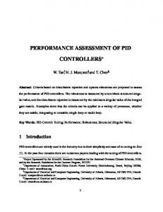
Wiring Diagram T2016 Series
T2016 Series (T20162 shown)
1.76” (44.8mm)
2.0” (51.0mm) includes gasket
Comms option (when fitted)
1.76” (44.8mm)
9
10 11 12 13 14 15 16
+
– + –
5Vdc 15mA
1
2.0” (51.0mm) includes gasket
4.57” (116.2mm) 4.2” (106.7mm) with gasket fitted
2
3
Sensor
Output SP1
Sensor S1
+ – SSR
Line
6
Output SP2
L 7
N 8
Supply
Open in alarm state
Load
F1
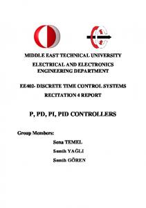
T2032 Series
T2032 Series
1.76” (44.8mm)
.87” (22.0mm)
1.12” (28.5mm) includes gasket
Comms option (when fitted)
4.57” (116.2mm) 4.2” (106.7mm) with gasket fitted
9
10
+
12
13
14
15
16
L
N
5
6
7
8
5Vdc 15mA
1
2
Sensor S1
Line
11
– + –
Sensor
Neutral
Specifications are subject to change without notice