Carnegie Mellon University
Research Showcase Computer Science Department
School of Computer Science
1-1-1985
PIE- a programming and instrumentation environment for parallel processing Zary Segall Carnegie Mellon University
Larry Rudolph
Follow this and additional works at: http://repository.cmu.edu/compsci Recommended Citation Segall, Zary and Rudolph, Larry, "PIE- a programming and instrumentation environment for parallel processing" (1985). Computer Science Department. Paper 1541. http://repository.cmu.edu/compsci/1541
This Technical Report is brought to you for free and open access by the School of Computer Science at Research Showcase. It has been accepted for inclusion in Computer Science Department by an authorized administrator of Research Showcase. For more information, please contact
[email protected].
NOTICE WARNING CONCERNING COPYRIGHT RESTRICTIONS: The copyright law of the United States (title 17, U.S. Code) governs the making of photocopies or other reproductions of copyrighted material. Any copying of this document without permission of its author may be prohibited by law.
CMU-CS-85-128
PIEA Programming and Instrumentation Environment for Parallel Processing Z a r y Segall and Larry R u d o l p h Department of C o m p u t e r S c i e n c e C a r n e g i e - M e l l o n University 26 April 1985
Abstract T h e issues of the efficient development of performance efficient parallel programs is explored. T h e Programming and Instrumentation Environment for Parallel Processing (PIE) system's c o n c e p t s , designs, and preliminary implementation results are presented. T h e key goal in P I E is semiautomatic generation of performance efficient parallel programs. In PIE, a system intensive rather than programmer intensive programming environment is promoted for supporting users with different experience in parallel programming. T h r e e levels of s u c h support are provided, namely the Modular Programming Metalanguage, the Program C o n s t r u c t o r , and the Implementation Assistant. In order to facilitate the task of parallel programming, each c o m p o n e n t employs a set of new c o n c e p t s a n d approaches to integrate functionality with performance c o n c e r n s . S o m e of them are: programming for observability, semantic monitoring, relational parallel program representation, constraint driven abstract data types (frames), frame unfolding, programming with templates, and parallel implementation assistant. T h i s paper presents the results of P I E 1, the first of a three phase project.
This research has been supported in part by the Ballistic Missile Defense Advanced Technological Center under contract DASG-60-80-C-0057. The views and conclusions contained in this paper are those of the authors and should not be interpreted as representing the official policies, either expressed or implied, of BMDATC, Carnegie Mellon University or the U.S. Government.
26 April 1985 at 11:21
Table of Contents 1. Introduction 2. B a c k g r o u n d a n d Related R e s e a r c h 2.1. Sequential Programming E n v i r o n m e n t s 2.2. Parallel Programming E n v i r o n m e n t s 3. T h e Modular Programming M e t a l a n g u a g e 3.1. T h e C o m p o s i t i o n of an M P P r o g r a m 3.2. P r o c e s s e s 3.3. Frames 3.4. T a s k s 3.5. S e n s o r s 3.6. Naming in MP 3.7. S y n c h r o n i z a t i o n and C o o r d i n a t i o n 3.8. MP S u m m a r y 4. T h e P r o g r a m C o n s t r u c t o r 4.1. MP O r i e n t e d Editor - M P O E 4.2. T h e Status and P e r f o r m a n c e Monitor 4.3. T h e Relational Representation S y s t e m 4.3.1. R o a d m a p 4.3.2. P r o c e s s E x e c u t i o n Times 4.3.3. Invocation T r e e V i e w 4.3.4. Frame U s a g e V i e w 5. A Simple E x a m p l e 6. T h e Implementation Assistant 7. Status and C o n c l u s i o n s 8. A c k n o w l e d g m e n t
26 April 1985 at 11:21
1
1. Introduction A recurrent problem plaguing computer s c i e n c e is the underestimation of the software effort. E v e n from the earliest days, the hardware c o m p o n e n t of a major computer project has been viewed as requiring the most research and creative energy; only o n c e the hardware is completed d o e s the enormity of the software effort become apparent. T h e recent emergence of parallel processing is no exception.
F o r example, an overwhelming number of research efforts have been directed toward
describing various aspects of designing and implementing parallel processors, while there is a paucity of research addressing how one will actually program these machines. Parallel processing is a radical departure from the traditional sequential processing. machines that can execute extraordinarily large numbers of instructions per s e c o n d .
It promises T h e main
challenge n o w is not whether these machines can be built but whether they c a n be programmed in s u c h a way as to make effective use of the increased computing power. It is not the raw computing power that is important, it is the effective computing power.
E x p e r i e n c e indicates that the future
programmer of parallel processors will require assistance in order to make effective use of the machine and to efficiently p r o d u c e efficient parallel programs.
This paper describes one s u c h
environment, called the Programming and Instrumentation Environment (PIE).
Historically, the programmer of a parallel processor has been a rather knowledgable scientist or engineer w h o was burdened with the task of creating parallel applications using environments.
rudimentary
Detailed multiprocessor architecture and operating system knowledge as well as
intricate ability to manually map parallel algorithms into a parallel virtual architecture and an " e x t e n d e d " sequential languages, are just some of the hurdles s u c h users had to overcome. correct parallel program is not even the end of the task.
A
Often, the only reason for developing a
parallel program is for the real time performance. T h e difficult task of performance debugging and the interpretation of the feedback in the context of a rudimentary program environment requires an even more specialized and highly knowledgable programmer.
T h e criteria of s u c c e s s for a parallel programming environment should be evaluated against two metrics. First, the user interaction with the system should put the burden on the system rather than on the programmer. T h a t means, realizing a system intensive programming environment rather than a programmer intensive programming environment. S e c o n d , as noted above, efficiency in terms of the real speed obtained by parallelization of the problem, mapping it into and executing it onto a parallel p r o c e s s o r is the reason for applying a parallel solution to a computational problem. Accordingly, a programming environment oriented toward high performance parallel programs is of essential importance.
2
26 April 1985 at 11:21
T h e first problem is not unique to parallel processing. T h e same goal is laudable in the context of sequential processing.
E x p e r i e n c e s h o w s , however, that the increased number of dimensions
present in a parallel program makes the need for system support urgent.
Amplification a n d
adaptation of current techniques from sequential programming environments to the
parallel
programming environment could be the first step in the w a y of satisfying this n e e d . T h e s e c o n d problem is particular to parallel programming, and therefore, new techniques a r e required to fulfill the critical goal of efficient parallel programming.
T h e P I E system attempts to
address the above two problems and their related issues. In P I E , w e concentrate o n those aspects relevant to parallel processing. It is worthwhile noting the distinction between parallel and distributed or c o n c u r r e n t processing.
In c o n c u r r e n t processing,
there is a set of processes w h o s e executions are interleaved. T h e processes may share memory or may communicate via a message-passing mechanism.
T h e emphasis is o n correctness and only
some slight improvement in execution s p e e d is achieved d u e to overlapping I/O with computation. In distributed computing, there is a set of p r o c e s s e s executing o n distinct machines.
O f t e n the
programming goal is to coordinate the activities that o c c u r at physicallydisjoint locations and these activities usually involve data-base applications. Occasionally, the goal of distributed processing is an increase in execution s p e e d , however, since the communication overhead between processes is high, only a coarse grain parallelism c a n b e s u p p o r t e d . Communication is usually performed t h r o u g h a highly structured interprocess communication mechanism (IPC). In parallel processing there is a set of processes executing on a tightly c o u p l e d set of processors that either all share access to some shared memory or employ a very fast and efficient communication mechanism. T h e primary goal of parallel processing is a performance increase proportional to the number of processors.
An
orthogonal goal is reliability. In P I E , w e c o n c e n t r a t e our effort toward programming for performance efficient parallel programs. T h e PIE project is organized in three phases.
T h e first one, PIE 1 , is g e a r e d toward c o n c e p t
formation a n d feasibility study. It has b e e n implemented using a number of V A X 11 /780 computers and professional workstations. P I E 4, to b e e x e c u t e d in a multiprocessor V A X 11/784 and M i c r o V A X workstations, is under a d v a n c e d design a n d implementation.
P I E 100, the third project phase, is
geared toward the Supercomputer W o r k b e n c h ( a large multiprocessor system under development at C M U ) . Currently, P I E 1 is essentially complete a n d hence most of the material in this paper relates to the P I E 1 phase. T h e paper is organized as follows. Programming
environments
and, in particular,
parallel
26 April 1985 at 11:21
3
programming environment are first reviewed. T h e next three sections are c o n c e r n e d with the three components of the PIE system: the modular programming metalanguage, the program constructor, and the implementation assistant.
T h e c o m p o n e n t s are organized a c c o r d i n g to their level of
abstraction and user support with the highest level providing expert system support for parallel program development.
T h e c o n c e p t s described in these sections are illustrated by a sample
application presented in section 5. Finally, section 7 presents the c o n c l u s i o n and current status of the PIE project.
2. Background and Related Research This section serves as a general introduction to programming environments.
We review both
sequential and parallel programming environments.
2.1. S e q u e n t i a l P r o g r a m m i n g E n v i r o n m e n t s At the foundation of a programming environment there are, in general, three types of components. First, a set of one or more programming languages is required . T h e programming languages may be of general purpose flavor or may support specific types of applications.
S e c o n d , a program
constructor facility provides an integrated interface between the programming languages, the user and the system utilities.
Aside from supporting the individual user, the program constructor may
facilitate multiple programmers' project support.
Recently, there are notable efforts to enrich the
program constructor's functionality with task specific information. Examples of program constructors are syntax-oriented editors and some recent efforts on semantic-oriented editors.
T h i r d , run-time
d e b u g g e r s of different flavors are essential for following and correcting a program's run-time behavior.
Currently, there are a few efforts aimed at building sequential programming
environments.
Although the emphasis is somewhat different in each of these systems, interactive system support for program development seems to be a common goal.
T h e Cornell Program Synthesizer [20] has a program constructor based on a syntax-oriented editor. Using attribute grammars to describe the program constructor generator output, this system could be used for a number of programming languages.
T h e C O P E [2] system, also from Cornell, uses an
editor c o u p l e d with an error correcting parser to automatically correct users' program constructs, as they are entered.
U n d o , redo, editing and execution features provide a minimal connection and
feedback mechanism between program development-time and run-time.
A major effort at C M U on programming-in-the-small and programming-in-the-large has produced
4
26 April 1985 at 11:21
the G A N D A L F programming environment [8]. T h e program constructor is again a syntax or language oriented editor - A L O E . T h e internal structure of programs in an A L O E is a parse tree, and the editor p r o d u c e d is template-oriented. At Xerox P A R C a number of programming environment prototypes have b e e n e x p l o r e d . Notable is the Smalltalk environment [ 1 3 , 5 ] .
Smalltalk is object and message oriented and makes use of
graphics to facilitate the manipulation of objects. T h e Smalltalk environment is language d e p e n d e n t and makes heavy use of the capability of interactive graphics display. Another programming environment based on Smalltalk is C E D A R [12]. T h i s system supports an algebraic, compiled language with interactive graphics-oriented
programming
interface
using
multiple windows. Recently at B r o w n University, a graphic-oriented programming environment effort, P E C A N [16], has been started.
In P E C A N , the emphasis is. on programming for observability, multiple views, a n d
exploration of graphical programming.
2.2. Parallel Programming Environments As previously stated, at the foundation of a programming environment is a class of programming languages. Almost all programming languages currently supporting c o n c u r r e n t processing (e.g. A d a , Modula2, C S P ,
OCCAM,
Edison, Concurrent
Pascal, etc.)
programming, as well as constructs for supporting
provide c o n s t r u c t s for
sequential
c o n c u r r e n c y control, communication
and
synchronization. W h e n moving the domain of application into parallel processing, additional features are needed for achieving efficient mapping of parallel machines. T h i s include constructs for: • parallel entities manipulation • virtual machine mapping • efficient use of shared memory (when relevant) • programming for observability • performance/correctness debugging S u c h support c o u l d be integrated in the programming language itself by e x t e n d e d the semantics, or could be provided as a set of procedures callable from the programming l a n g u a g e itself. G i v e n the fact that this support will most likely be language independent, an alternative is to provide the parallel language support in language independent manner.
This support c o u l d b e in a form of a
26 April 1985 at 11:21
metalanguage.
5
T h e metalanguage is then the medium in which to express and manipulate all the
parallel constructs. T h e sequential constructs stay in an existing programming language. W h e n the programming language is not a concurrent programming language (ex. Fortran), the metalanguage covers synchronization and communication primitives as well.
Currently, there are a number of research efforts in the area of parallel programming environments. A distinct class is related to the vectorization of existing languages. Most notable is the Paraphrase [11] automatic vectorizing compiler research at the University of Illinois.
Although well-suited for
taking advantage of vector programs, the Paraphrase compiler does not provide support for creating new superior parallel software for a general class of computer structures.
Another interesting research effort is P O K E R at Washington University [19]. program constructor and is specialized to mapping
P O K E R provides a
a virtual application architecture into a
configurable V L S I parallel architecture.
A set of relevant, programming environment efforts c o m e from the area of distributed programming. A D L / A D S [6] developed by T R W is a language with an interactive graphic user interface, targeted toward mapping a distributed application into a distributed system.
T h e language has constructs
enabling the user to describe both virtual and physical system structure and to map a distributed program over the described structure. information of the system behavior.
Significantly, an instrumentation system provides run-time
Matchmaker [10], at Carnegie-Mellon University, is a program
providing for distributed program construction by hiding some of the more cumbersome details of interprocessor communication from the user.
3 . The Modular Programming Metalanguage T h i s section describes the modular programming metalanguage, which is the first of the three components of the PIE system.
T h e other two components, the program constructor and the
implementation assistant, are described
in subsequent sections.
T h e goal of the
modular
programming (i.e. MP) metalanguage is to provide support for the efficient manipulation of parallel modules,
fast parallel a c c e s s to shared data constructs, and programming
for observability
in a
language independent fashion. T h e MP metalanguage allows the programmer to specify most of the c o d e in his o r her favorite programming language.
Moreover, MP assumes a run-time environment
that supports its abstractions and its monitoring directives. In this section, w e describe the MP metalanguage that has been implemented in PIE 1.
6
26 April 1985 at 11:21
3.1. T h e C o m p o s i t i o n of an MP P r o g r a m In MP, the programmer views the computation as a s e q u e n c e of serial and parallel operations. E a c h parallel operation may consist of another set of computations that are executed in parallel.
Since
each computation itself c a n be c o m p o s e d of a s e q u e n c e of serial and parallel operations, the programmer may not know how many p r o c e s s e s are e x e c u t e d in parallel. T o realize the goal of a clean separation of c o n c e r n s , the programmer must be able to c o d e or specify parts of the program without a detailed knowledge of the whole computation. T o this e n d , a set of logical entities h a v e been developed so that the programmer c a n concentrate on the correct functioning of each module; the system automatically converts the logical entities and their specifications into an executable parallel program.
It is envisioned that additional optimization, both compile-time and run-time, of
c o n c u r r e n c y control conditions will minimize the synchronization o v e r h e a d . MP provides the ability to observe or monitor the execution of a program. T h i s is accomplished through the sensor module. A s e q u e n c e of serial operations is referred to as a process
and a parallel
operation is referred to as a task. A set of tasks that share the same protection e n v e l o p e is referred to as a task group.
A c c e s s and management of shared memory is specified in a frame.
3.2. Processes A process is a sequential program written, at least in theory, in any sequential programming language. T h e process construct includes the set of local declarations, local data, the process b o d y , and instrumentation. Sequential languages are extended by the MP environment to give support for synchronization, initiation of parallel operations, access to shared data, and monitoring directives associated with process functions. T h e motivation for these extensions is to allow the programmer to concentrate on the limited set of c o n c e r n s at h a n d . For example, Figure 3-1 s h o w s sample p r o c e s s c o d e for a tree insertion routine.
Note that the c o d e is written without specifying locks or
synchronization. T h e s e issues are relegated to the frame constraint c o d e . W e have found it useful to c o d e using frame operations that modify shared data structures based on the results of some test of shared data structures. In this way, c o n c u r r e n c y constraints can be easily satisfied and the process c o d e need not be c o n c e r n e d with the details of the s h a r e d data structures. For example, in the Insert process of Figure 3-1, a frame operation is u s e d that adds an item to the tree only if the process is at a leaf n o d e of the tree. T h e frame operation also indicates whether this occurred.
7
26 April 1985 at 11:21
Process Begin
Insert(x:item) SMoveToRoot; Repeat Switch
Until
=
SCompare(x) Begin Case -1: SMoveToRightChild; C a s e +1: SMoveToLeftChild; Case 0: Exit;
End; SAddlfleaf(x);
End F i g u re 3 - 1 : Process c o d e for insertion in a binary tree. Note that the c o d e is written without knowledge of other parallel activity. T h e frame operations, identified by the symbol $ , provide a c c e s s to shared data structures. M
M
3.3. Frames Communication between processes on a tightly-coupled multiprocessor is often more efficient when shared memory is manipulated directly by the processes than when they e x c h a n g e information solely through message passing, interprocess communication mechanisms ( I P C ) .
E x p e r i e n c e has
s h o w n , however, that indiscriminate use of shared memory promotes 'hard to find
1
bugs.
MP
attempts to alleviate this problem by providing facilities for controlled a c c e s s to shared memory. Separation of c o n c e r n s is achieved through shared data encapsulation and shared abstract data types. MP thus introduces the notion of a frame.
Logically, a frame consists of declarations of shared
data, a set of operations on shared data, constraints on the execution of these operations, and monitoring directives associated with the shared data and its access. An interprocess communication mechanism (IPC), which is supported in many operating systems, is an example of frame operations. T h e IPC mechanism is usually implemented as a queue in w h i c h a send is a queue insert and a receive is a queue delete with the q u e u e hidden from the caller and with a strictly enforced synchronization protocol.
Although a frame is logically a single entity, in reality its operations are
'unfolded' automatically into the process c o d e with appropriate coordination c o d e where necessary. Moreover, frames give a clean extension to serial programming languages. From the user's point of view, access to shared data is accomplished through procedure calls that appear to the programmer as monitors [9, 3]. It is important to note that frames are not monitors; monitors provide strict mutually exclusive a c c e s s to shared data whereas frames allow potentially unrestricted accesses to o c c u r in parallel.
Frames consist of abstract shared data types, shared data encapsulation, and
constraints.
Associated with the data types are a set of operations, some of which are visible to the process c o d e . T h e frame c o d e for these operations may refer to any of the encapsulated data as well as to any of the
8
26 April 1985 at 11:21
internal manifest variables (explained later in this section in detail) s u c h as the caller's p r o c e s s name or index described below.
Frame operations may also refer to other frame operations.
Figure 3-2
s h o w s sample frame specifications for the tree insertion p r o c e s s presented in Figure 3-1.
A local
variable is declared for the use by each p r o c e s s . Visible functions and procedures can be used in p r o c e s s and other frame c o d e . Coordination and synchronization required for correct parallel a c c e s s to shared memory is specified by constraints o n the parallel e x e c u t i o n of these operations. T h e constraints can b e regarded as a generalized form of path e x p r e s s i o n s [ 7 , 4 ] or path predicates [1] on the frame operations. T h e s e expressions specify both what s e q u e n c e s are required and what parallel actions are forbidden. Anything left unspecified is assumed to b e unrestricted and may o c c u r in any order or in parallel. T h e constraints c a n control a c c e s s finer than just frame operations. For example, parallel access to different elements of an array may be allowed provided that there is no parallel a c c e s s to any particular element and that no element can b e referenced until it has been initialized. Figure 3-3 s h o w s sample constraint specifications for these operations. T h e operation names a r e listed with free or b o u n d variables as parameters. T h e symbol " . " indicates that the parameter value plays no role. T h e parameters following the operation name and placed between the brackets ( " [ " and " ] " ) indicates w h i c h variables, of type either local o r other, are required to match in order for the constraint to hold.
In the example, each different TreeNode
value has a separate constraint.
The
system c a n realize t h e s e constraints, for example, b y automatically allocating a lock with e a c h o c c u r r e n c e of a TreeNode
a n d inserting the p r o p e r lock protocols.
Figure 3-4 s h o w s the frame c o d e unfolded into the p r o c e s s c o d e . T h i s is performed mechanically, and since the AddlfLeaf operation is exclusive o n each node in the tree, the system automatically assigns a lock to each node. Moreover, from the specification, it is derived that the other operations c a n o c c u r in parallel with e a c h other but not with AddlfLeaf and h e n c e readers/writers coordination is automatically inserted. Divide and c o n q u e r , a common algorithmic paradigm, is supported by the M P environment. Here, a part of shared data is often subdivided with each subpart processed independently and in parallel. A frame partition operation and the notion of a hollow frame support decomposition into subproblems and allow the p r o c e s s c o d e to be written without knowing whether it is solving a problem or a subproblem. T h e partition operation r e c o r d s h o w a shared array is to be divided.
A hollow frame
maps a part of a shared data array into an entire virtual shared data array. A particular instance of divide and c o n q u e r is when the subproblems a r e solved recursively. T h i s style is supported by M P
26 April 1985 at 11:21
Frame Tree Type
Local
9 Manipulation
TreeNode
= Record Begin Item : i n t ; Left, Right End; •
:
"TreeNode;
P:"TreeNode;
{ Allocation Shared
of Shared Memory Data Structure } Root : " T r e e N o d e ; RootLeaf : TreeNode;
Initialization: Begin R o o t ;= R o o t L e a f ; Root.Item : = Nil; R o o t . L e f t := N i l ; Root.Right : Nil; s
End; Visible Function $Compare(x : i n t ) : Boolean Begin If x < P. I t e m T h e n SCompare : -1 E l s e If x = P. I t e m T h e n SCompare* : E l s e SCompare : - 1; End a
s
{ Some operations
Visible Begin
0
are omitted }
SMoveToLeftChild P :«
P.Left;
End; { The following operation modifies the tree, inserts the item, if we are currently pointing at a leaf node. The results of this test are returned. Visible $ A d d I f L e a f ( x : i n t ) : Boolean Begin If P. I t e m != Nil T h e n R e t u r n ( F a l s e ) Else Begin P . I t e m := x ; P. L e f t : = N e w ( T r e e N o d e ) ; P.Right : New(TreeNode); Return(True) End End;
}
s
F i g u r e 3 - 2 : Sample frame specifications for the tree insertion p r o c e s s presented in Figure 3-1.
10
26 April 1985 at 11:21
Constraint Forbidden:
( F o r A l l t in
{TreeNode}) S A d d l f L e a f ( . ) [ T r e e N o d e : f] with {$Compare( . ) [ T r e e N o d e : f] U $MoveToRoot[TreeNode: f] U SMoveToLeft[TreeNode: f] U $MoveToRight[TreeNode: f] U SAddlfLeaf(.)[TreeNode: f] }
End Constraint Figu re 3 - 3 :
Sample constraint specifications,
and the run-time system maintains a hierarchical, dynamic, naming s c h e m e for MP entities.
3.4.Tasks A task contains all the necessary specifications for a parallel operation.
A p r o c e s s wishing to
initiate a parallel activity just invokes a task. A parallel operation consists of a set of processes that cooperate in some fashion, often through shared memory.
A task therefore consists of a set of
processes, a set of frames, and control information. In addition, tasks specify monitoring directives for the whole task as well as resource allocation. R e s o u r c e allocation is usually d e p e n d e n t on the resources supplied by the target machine a n d often includes specifications as to h o w processes a r e to be mapped onto processors, what scheduling policies should be u s e d , and how shared memory is to be mapped onto physical memory. T h e MP metalanguage enforces scoping in a manner similar to that found in block-structured sequential programming languages. Part of the specification of a task includes p r o c e s s definitions, frame definitions (abstract shared data type declarations), and task definitions.
E a c h logical entity
can reference other logical entities that are within its s c o p e . T h a t is, entities that are defined in the same task or in an outer task can be referenced. (See, for example, Figure 5-1.)
A library of
predefined abstract shared data types and some standard tasks and p r o c e s s e s are visible throughout the program and are arranged in system libraries in much the same way as are I/O packages.
3.5. S e n s o r s In addition to specifying the actions and constraints of a parallel program, MP also provides the ability to observe or monitor the execution of a program. T h i s is accomplished b y instrumenting program by inserting sensors
a
into the program. T h e implementation of the s e n s o r s is automatic and
may be in hardware or software, depending on the system. M P supports four types of sensors: time c o n s u m e d by a task or process, time required to execute a block of c o d e , the value of a variable, a n d user defined. T h e first type is always inserted automatically by MP. Figure 3-5 s h o w s the monitoring of a block of process c o d e as well as the monitoring of the value of the parameter. T h e PIE system
26 April 1985 at 11:21
Program
Insert
=
{ The frame's data structure declarations are unfolded into each process and for each frame that it references. Note the lock allocation that has been inserted with each TreeNode. } Type TreeNode = Record Begin SSemaphoreOOl : L o c k ; Item : i n t ; L e f t , Right : "TreeNode; End; { Access to shared memory is achieved in Pascal by allocating record that specifies the shared memory structure. } SharedMemory = R e c o r d Begin Root : " T r e e N o d e ; RootLeaf : TreeNode; End; var
P :
"Treenode; SharedMemoryPtrOOl x : int;
:
a pointer to a
"SharedMemory;
{ The frame operations are unfolded into the Pascal code for the process along with the inclusion of synchronization code realizing the constraints.} Function $AddIfLeaf(x : int) Begin SBeginWri ters(P.SSemaphoreOOl): If P. I t e m != Nil T h e n R e t u r n ( F a l s e ) Else Begin P . I t e m := x ; P.Left : New(TreeNode); P . R i g h t := N e w ( T r e e N o d e ) ; Return(True) End; SEndWriters(P.SSemaphoreOOl); End s
( Note that in the following body code that the frame operation unfolded as well as the inclusion of synchronization code. } Switch
SCompare(x)
C a s e +1:
has been
Begin
Begin $BeginReaders(P.SSemaphoreOOl) P := P . L e f t ; $EndReaders(P.SSemaphoreOOl); End
End; Figure 3-4:
Frame and synchronization c o d e are unfolded into the p r o c e s s code.
12
26 April 1985 at 11:21
integrates the job of monitoring and does all the associated bookkeeping.
MP and the run-time
system generate and maintain unique identifiers for each of the sensors as well as associating the point in the program specification w h e r e the sensors have b e e n inserted by the programmer.
Thus,
when viewing the results of a particular sensor, the programmer c a n also see surrounding the c o d e and specifications. In Figure 3-5, the block sensor requires the insertion of two sensors each with the same identifier. Process I n s e r t ( x : i t e r n ) * Begin ~Begin_Process_Sensor(17); ~Variable_Sensor(12,x,"item"); SMoveToRoot; ~Begin_81ock_Sensor(7); Repeat Switch SCompare(x) Begin SMoveToRightChild; C a s e -1 SMoveToLeftChild; C a s e +1 E xit; Case 0 End; Until S A d d l f L e a f ( x ) ; ~End_Block_Sensor(7); ~End_Process_Sensor(17); End F i g u r e 3 - 5 : Process c o d e of Figure 3-1 with sensors inserted. T h e B e g i n / E n d _ P r o c e s s _ S e n s o r s are always inserted and the 17 is associated with this process. T h e Block sensors were inserted at the direction of the programmer with the identifier 7 generated by MP and associated with this block.
3 . 6 . N a m i n g in M P T h e ability to recursively invoke tasks and to create distinct instantiations of the various entities requires particular care be given to the naming issue. E a c h entity of type task, process, or frame, has three names: local, static, and dynamic. T h e local name is the o n e assigned by the programmer a n d is a single alphanumeric identifier. (For example, in Figure 3-1, the local p r o c e s s name is "Insert".) T h e static name is based on the static s c o p i n g of MP. separated
by the delimiter
"/"
and
terminated
It consists of a list of local task names
by the
entities
local
name
(For
example,
"Outer/Master/Slaves"). S i n c e there c a n b e multiple c o p i e s of a p r o c e s s , the dynamic local p r o c e s s name is the local name of the p r o c e s s followed by the delimiter " . " and the index of the p r o c e s s instantiated (for example "siave.4").
T h e dynamic naming structure is similarly structured in a
hierarchical fashion but reflects the s e q u e n c e of task invocations leading to its instantiation.
The
dynamic name is a list of alternating task a n d p r o c e s s dynamic local names again separated by the delimiter " / " and terminated by the dynamic local name (for example, if " O u t e r " and "Master" a r e task
names,
and
"Init"
and
"Slave"
are
local
process
names
then
26 April 1985 at 11:21
13
"Outer/lnit3/Master/Slave.5/Master/Slave.4" could be a d y n a m i c p r o c e s s name).
3.7. Synchronization and Coordination T h e problem of synchronization and coordination is a major c a u s e of c o n c e r n in parallel processing. In MP, the problem is mitigated in three ways: Tasks, Frames, and Events. Frames deal with synchronization and coordination details related to a c c e s s to shared memory. Tasks deal with the initiation and termination of sets of processes. Although these two mechanisms are sufficient to handle all synchronization problems, a third kind of support is often useful. Specific execution points within a process are labeled and marked as events. Within the task specification, the user can specify constraints using these events in order to s y n c h r o n i z e the processes within a task. T h e s e expressions or predicates are used to control processes as well as frame operations.
T h e constraints require the use of certain run-time status values. T h e s e manifest
variables may or
may not be actually maintained during run-time; their main use is to allow the programmer to form constraints in terms of these variables; the system may be able to realize the constraints in a simpler fashion. T h e manifest variables are similar to the shadow auxiliary variables introduced by Owicki and G r i e s [ 1 4 , 1 5 ] . Some examples include: the P r o c e s s _ D y n a m i c _ N a m e
w h i c h is unique for each
instantiation of a process and the associated P r o c e s s e d is a unique integer. T h e P r o c e s s _ I n d e x can be derived from the P r o c e s s _ D y n a m i c _ N a m e and indicates the unique instantiation of process when multiple copies have been initiated. T h e P r o c e s s _ D e p t h is an integer that identifies how many times a p r o c e s s has been recursively invoked. T h i s value is derived by counting the number of times the process name o c c u r s within the P r o c e s s _ D y n a m i c _ N a m e . Finally, an event or execution count, • . C o u n t where * is an event or frame operation identifier, is available that records the number of times the event or frame operation has been executed for each unique process instantiation Associated with each of these manifest variables is a set containing the universe of values for these variables.
3 . 8 . MP S u m m a r y Figure 3-6 reviews the basic "modules" of a task in MP. It describes the various specifications of a task as well as the other modules comprising a task. Note the distinction between definitions and references. A process may be defined in one task but only included in tasks that are defined within the task.
14
26 April 1985 at 11:21
• Task o Definitions. (Statically s c o p e d ) . • Process Definitions. A complete program in an extended serial programming language. Monitoring directives c o n c e r n i n g aspects of the process state. Points in the program marked as events with associated names. • Abstract Shared Data T y p e Definitions. Describes the shared data declarations, the hidden and the visible operations, and the a c c e s s control of these operations. A data initialization specification c a n also b e supplied. Monitoring directives c o n c e r n i n g the values of the shared constructs as well as monitoring the time spent waiting for synchronization. • Task Definitions.
T h i s definition provides static scoping of the logical
entities. o Body • Processes. T h e set of p r o c e s s e s that are to be e x e c u t e d in parallel w h e n the task is invoked along with a repetition c o u n t indicating that there are to b e multiple copies of the p r o c e s s . • Frames. Binds names to instances of the shared data types. T h i s represents the data that is common to all processes a n d frames in this s c o p e . o Control • Process C o n t r o l . Generalized path expressions specifying initiation and termination conditions for the processes and for the task. Constraints are specified in terms of instances of the entities, global variables, and events. • R e s o u r c e Allocation. Mapping p r o c e s s instantiation to processors: for each instance of a p r o c e s s either a specific p r o c e s s o r is suggested, any o n e in a class of processors are suggested, or the system is free to allocate as it pleases. W h e r e shared memory is to be allocated and whether or not the pages c a n be s w a p p e d is specified. • Monitoring Directives. Specifications as to whether any particular configuration of the processes should b e noted. T h e system, by default, monitors the initiation and termination of e a c h instance of a task.
F i g u r e 3 - 6 : A summary of the modules and their meaning for the specification of a parallel program in the MP environment.
26 April 1985 at 11:21
15
4. The Program Constructor T h e Program Constructor ( P C T ) is the s e c o n d component of the PIE system. It provides a higher level of abstraction and support for the generation of efficient parallel programs.
T h e P C T builds
upon the concepts introduced by MP a n d frees the user from much of the detailed specification of an instrumented
parallel program.
T h e P C T is unique in that it provides mechanisms and policies for combining a n d transforming both the development time (static) and the run-time (dynamic) information into meaningful program representations.
T h e static information is combined with status and performance information to
provide semantically meaningful performance feedback w h i c h , in our view, is the key for generating performance efficient parallel programs.
T h e PIE P C T can be d e c o m p o s e d into three main components: • An MP oriented editor - M P O E • A status and performance monitor • A relational representation system T h e transformation and integration of dynamic and static information is based on using the relational model approach. T h e M P O E internal representation is in the form of both a parse tree and relational model, with the former required for the syntax directed editor and c o d e generation part of M P O E and the latter to c o n v e y static program information to the two other c o m p o n e n t s of P C T .
T h e Status and Performance Monitor is also based on the use of the relational model [18,17] to select, filter, and collect run-time status and performance information.
Accordingly, the relational
model will contain static and dynamic information along with the semantic and temporal relations between them. T h e Relational Representation System then extracts and selects the views relevant to a specific performance or status goal.
T h e rest of this section describes each of these components in detail.
4.1. MP O r i e n t e d E d i t o r - M P O E T h e user (or programmer) of the MP environment, specifies and c o d e s the parallel program through a syntax directed editor. While the study of structured editors is still a very active area of research, the PIE system requires only a few salient features that are c o m m o n to most of them. T h e editor is the interactive interface between the user specifying a solution to an application problem, the extended
16
26 ApriM985 at 11:21
programming
language, the system utilities, a n d the rest of the P I E system.
Our
current
implementation employs a G A N D A L F - t y p e of syntax-directed editor [8] refered to as M P O E . T h e user is presented with a partially constructed parse tree consisting of nonterminal and terminal nodes. A s the user enters program information, the nonterminals are e x p a n d e d , the parse tree is refined, a n d some semantic action affecting the contents of the relational model may o c c u r . F o r example, w h e n positioned at the nonterminal node for the identifier of a p r o c e s s module, the name entered by the user causes the parse tree to be further refined, the screen updated, and an addition to the relational model indicating the existence of this p r o c e s s along with other information s u c h as w h e r e in the parse tree the specification o c c u r r e d . T h e M P O E consists of two parts o r grammars, one for describing and specifying most of the modules of MP and one for each of the programming languages in which the p r o c e s s c o d e can b e specified.
T h e root of the parse tree is a task and the children are (i) the p r o c e s s and frame
definitions, (ii) the process and frames instantiations that are the run-time composition of the task, (iii) the control specifications, (iv) the task monitoring directives, and (v) the tasks that are within the s c o p e of this task. In MP, separation of c o n c e r n s is achieved through the use of many modules. Although this allows the programmer to concentrate on only a narrow range of program aspects, a typical program may contain a large number of instances of these modules w h o s e maintainance and organization may become a problem. T h e static scoping rules of the definitions helps to isolate disjoint parts of the program; entities not within the outer s c o p e can not be referenced.
T h e M P O E enforces this
restriction in an interactive fashion. T h e M P O E , however, d o e s not just tell the programmer when he can not reference an entity; it also helps the programmer to see what entities are available at e a c h point in the specification. A roadmap of the program that dynamically displays the s c o p i n g structure of the modules is part of the graphical user interface. As each module is specified, the M P O E notifies the rest of the P I E system. T h i s c a u s e s an update to the PIE central relational model and may also update some of the graphical views of the program specification. A link is created between the user's s o u r c e c o d e or specification, the internal objects of the PIE system, and the final executable c o d e . T h i s is useful, for example, w h e n the user queries the result of a monitoring sensor. At the same time as the value is related to the user, the PIE system c a n also present the user's specification of the sensor and its surrounding c o n t e x t in MP.
T h e M P O E also provides a mechanism of selective viewing.
It is often the case that event
specification within the process c o d e or the monitoring directives are intrusive and clutter the users
26 April 1985 at 11:21
17
view of the program specifications. T o o many events or monitoring directives make the control flow of the program hard to follow and often make the display of a simple procedure span multiple screens. Similarly for frame operations that have long static names and make the display of statements span multiple lines. T h e user c a n request that event and monitoring specifications not be displayed and that frame operation names be shortened.
Finally, syntax-directed editors have much knowledge about the program as it is being specified. This knowledge can be used with another component of the P I E system in order to give advice to the user about the specification. F o r example, in a Master/Slave implementation, the knowledge of the entities of the partially specified program enable the Implementation Assistant, described in the next section, to advise the user about where to place the c o d e to handle fatal exceptions raised by a slave process.
4.2. The Status and Performance Monitor T h e development of a correct and efficient parallel program is accomplished through a series of phases s u c h as s o u r c e editing and specification, compilation, correctness and
performance
debugging, and optimization." In PIE, the role of monitoring is to observe the later phases of the program development and to provide significant information to the user or to the system.
The
monitoring environment is c o m p o s e d of sensors, monitoring directives, and presentations of sensor recordings. S e n s o r s are currently implemented mainly in software although research is underway to build hardware sensors. T h e r e are two types of sensors, system and user defined. T h e user specifies monitoring directives throughout the MP specifications indicating which of the system sensors are to be enabled and the composition of the user defined sensors. After the parallel program is executed, the results of the sensors can be seen through various graphical views that are under the user's control.
T h e monitoring " p h i l o s o p h y " in P I E is based on the insertion of special objects, named sensors, into the user c o d e during program development. It has the following main characteristics: • It detects a precisely defined event, which may be the execution of a statement, a p r o c e d u r e call, an a c c e s s to a variable, or a more complex, user defined function of the computational status of the program. • It c a u s e s a transfer of information from the program to an external environment in an automatic and controlled way. • It is transparent to the correctness of the program a n d makes every attempt to be transparent to the performance of the program.
18
26 April 1985 at 11:21 • It can be enabled or disabled under the control of a standard, external mechanism. T h i s allows a standard and possibly automatic instrumentation of a program at development time and a customization of monitoring requirements at run-time.
Sensors are inserted into the application c o d e in a controlled way, using the M P O E w h i c h is also responsible for storing all the information about their names, type, and location in a central relational database. T h e run-time environment also r e c o r d s the information gathered into the relational model. T h e user views the information from the relational model in a graphical and interactive fashion. Logically, a sensor is c o m p o s e d of three parts: Detection, isolation, and notification. T h e r e are four types of sensors: Start/stop object, start/stop block, variable monitoring, and user defined. T h e first two record the spatial and temporal status of the starting o r stopping of a task, process, frame, o r block of c o d e within a p r o c e s s or frame operation.
T h e variable monitoring sensors record the
contents of variables at run-time. Different sub-types are provided for e a c h basic data type of the language. T h e user-defined sensors allow for greater flexibility and filtering. T h e user provides a set of routines that are e x e c u t e d whenever a s e n s o r is enabled and invoked. T h e r e is a standard format for transferring information to the relational model. T h e ability to instantiate multiple c o p i e s of a task or p r o c e s s and, in particular, the ability to recursively instantiate tasks makes the enabling/disabling of sensors difficult.
S e n s o r names are
based on their location (i.e. the name of the logical entity within w h i c h they were specified) and have static and dynamic names. S e n s o r s can b e dynamically or statically enabled. A sensor enable table ( S E T ) is maintained which is c h e c k e d each time a sensor is e n c o u n t e r e d . T h e table contains both dynamic and static names as well as a specification of a class of names based on a wildcard specification. Dynamic enabling of a task is accomplished b y inserting appropriate commands in the user's application c o d e . T h e static enabling of sensors is most easily performed by first executing the application with all system supplied s e n s o r s enabled and then pointing to parts of the views of the computation to enable or disable sensors nested d e e p within the computation. Based o n previous e x p e r i e n c e with parallel processors, the monitoring system is the conceptual backbone in providing the c o m p o u n d event observability, a critical issue in the p r o c e s s of efficient parallel programming. T h e P I E system is angling towards a prototype parallel processor that will dedicate a substantial part of the multiprocessor hardware specifically to instrumentation.
Main
expected advantages of hardware instrumentation are non-intrusiveness (minimal cost or z e r o c o s t associated with detection, isolation, composition and notification of an event), wide range (from low grain hardware events to large grain events), and adaptability t h r o u g h programmability.
These
26 April 1985 at 11:21
19
aspects provide the incentives for intensive use of instrumentation not only in evaluation, but also in operating systems design and programming environment.
performance
S u c h a parallel
processor (i.e. the Supercomputer Workbench) is under development at C M U .
4.3. T h e Relational Representation S y s t e m W e wish to give the parallel program developer all the help possible. provides support for specifying the program.
T h e MP metalanguage
In order for the developer to p r o d u c e a correct and
efficient program, the PIE system supports the notion of programming
for observability.
Multiple
representations of the syntactic and semantic information are made available at both developmenttime and at run-time and are supported in an integrated fashion. T h e syntactic MP information is maintained in the M P O E parse tree. T h e modules defined in MP, s u c h as Process, Frame and Task, are directly visible and can be manipulated through M P O E . T h e M P O E parse tree contains the relevant development-time instrumentation information, such as sensor location, c o d e , and associated data structures. In order to integrate the specification with the rest of the PIE system, a relational model (from data base domain) is used. Information from MP as well as information accumulated during run-time is maintained in the database. W h e n relational operations are applied to the relationally structured information, multiple views of the same information are obtained. T h e s e views all help the programmer to understand the subtle interactions and bottlenecks of the program.
A representation is a form of expressing a parallel program a n d / o r its behavior.
Examples of
representations are: • Communication graph and communication tree • Process graph and process tree • Process-resource graph and p r o c e s s - r e s o u r c e tree • Dependency graph and d e p e n d e n c y tree T h e graph presentations are the development-time representation, whereas the tree refers to the same representation at run-time.
For example, the specification view of a recursive, divide-and-
c o n q u e r application will be a graph with self-loops indicating recursive invocations whereas, the dynamic run-time view will be a tree with each n o d e representing a particular instantiation of a module.
A representation integrates the graphical screen presentation control together with the
behavior and observability information (e.g. selective monitoring of relevant events).
20
26 April 1985 at 11:21
In PIE, the M P O E parse tree is dynamically restructured into an I N G R E S - l i k e relational model as the user performs the M P O E program development actions. At run-time, a relational monitor will p r o d u c e relationally organized monitor information, stored in the same relational data structure. T h e relational data structure integrates the development-time information and the run-time information. B y using the view feature of the relational model, along with presentation control information specific for e a c h representation, a number of different representations c a n be displayed. T h e integration of development-time and run-time information in one representation provides the basis for the performance/correctness d e b u g g i n g process. T h i s is accomplished by providing: • Selective representation. T h e user c a n selectively observe c o m p o u n d events by specifying a representation definition relevant to a performance or correctness goal. • Integration between development-time a n d run-time information.
T h e user is getting
usable feedback w h i c h is directly applicable to the process of program development and performance tuning. • High-level and automated performance d e b u g g i n g .
T h e user describes the parallel
program and the required representation at high levels of abstraction.
T h e system is
generating ail low level interactions. T h e PIE system currently provides four views: roadmap, p r o c e s s execution times, invocation tree and frame usage tree. T h e complete filtering envisioned has not yet been incorporated into the system. It is expected that the user will be able to interact with the graphical views and indicate the objects that are not to be displayed. A major problem in the graphical presentation of the actions of a parallel program is the large amount of information that must be sifted t h r o u g h until the appropriate information is found. T h e relation model a p p r o a c h should make this job easier. 4.3.1. Roadmap T h i s is a view of the specification of the program. A s the user specifies a task, process, or frame with the M P O E , a corresponding object is displayed on the s c r e e n . T h e view also communicates with the M P O E so that a user c a n point to an object in the roadmap view and the M P O E will position the user to that part of the c o d e .
In this way, the user c a n get the "big picture" of the whole prgram
structure while concentrating on only a small part of the specifications. 4.3.2. Process Execution Times T h i s view displays the execution times of p r o c e s s e s in the form of a bar g r a p h with a separate indicator for each instance of a process. T h e g r a p h is dynamically drawn with the total execution time of the experiment divided into a number of " s l o t s " . For each slot during w h i c h a process is active t h e bar is blackened. T h e analysis of the database p r o c e e d s chronologically through the execution of the
26 April 1985 at 11:21
21
experiment giving the global effect of a visual tracing of the execution of all the processes in "slow motion".
T h e bar graph gives an immediate global view of the parallelism of the application as a
function of time. A useful feature is the ability to zoom
into part of the view in order to see a finer
grain of interaction. 4.3.3. Invocation Tree View T h i s view represents the dynamic invocation s e q u e n c e of tasks, processes, and frames of the experiment. T h i s view can be either static or dynamic. In the static case, each object remains in view o n c e it is created and in the dynamic case, the objects vanish from the screen o n c e they terminate. As an object is created, it is displayed on the screen and a line is drawn indicating the parent/child relationship. O n c e again, the view is displayed in "slow m o t i o n " thus presenting a motion picture as the computation unwinds. At any point, the user can select an object and in another window see the M P O E specifications of the object. 4.3.4. Frame Usage View T h i s view displays the dynamic reference to shared memory by processes or other frames.
The
actual implementation is part static and part dynamic. Frames and processes are displayed statically. O n c e again, the view p r o c e e d s chronologically through the database and as each reference to a frame is performed a line is drawn connecting the two entities. This view helps discover bottlenecks d u e to contention to shared objects.
5. A Simple Example In this section we demonstrate various features of the P I E system by describing an example application.
A naive parallelization of quicksort is the c h o s e n application d u e to its familiarity and
simple recursive structure. Quicksort starts with a set of numbers, divides the set into two subsets, and then recursively sorts them. T h e subsets are formed by choosing a candidate median value and placing ail elements smaller than this value into set S M A L L , those equal to o r greater than into set B I G . T h e naive parallelization recursively applies quicksort to the subsets S M A L L and B I G in parallel.
T h e r e are a few MP modules that are specified: a p r o c e s s either sorts the array if it contains only a few elements or divides the array into subsets and recursively applies quicksort to each subset. T h e process c o d e can be written in s u c h a way as to not know if it is executing in parallel with another process. E a c h process a c c e s s e s the array through frame operations. A hollow frame is specified that makes part of the array (either the set S M A L L or the set B I G that was created by the parent task) appear to be the whole array.
After the p r o c e s s rearranges the array into S M A L L and B I G sets, it
partitions the array and invokes the task Q T . T a s k Q T contains the hollow frame and two copies of
22
26 April 1985 at 11:21
the process. O n e c o p y of the process is mapped onto the set S M A L L and the other is mapped onto the set B I G . T h e hollow frame makes this distinction based o n the index of t h e processes and a c c e s s the data through the outer levels frame operations. Figure 5-1 s h o w s the outermost part of the MP specification of the quicksort program. T h e r e is a master p r o c e s s that reads the items to b e sorted and places them into the shared array through the operations provided by Frame global.
No
constraints were supplied s o that the master p r o c e s s will not wait for the parallel task it invokes to complete.
Also for simplicity, no extra task sensors have been inserted, h o w e v e r , the system will
supply a set of default sensors for the tasks. TASK
quick PROCESS m D U P L I C A T I O N 1 >Body< FRAME g l o b a l >Body< TASK QT >body< F i g u r e 5 - 1 : Part of the MP Specification of a naive parallel quicksort. T h e definition and reference to the processes and frames are c o m b i n e d .
In Figure 5-2 the inner task specification is presented. T h e r e are to be two copies of the process q instantiated whenever task O T is invoked. TASK QT PROCESS q D U P L I C A T I O N 2 >Body< FRAME s h a r e d >Body< Figure 5-2:
Part of the MP Specification of a naive parallel quicksort. T h i s is the recursive quicksort task definition.
In Figure 5-3 some of the frame definitions are s h o w n . T h e variables Low, H i , N e w L o w , and N e w H i are used to keep track of the remapping of the array.
T h e first two r e c o r d how the array was
partitioned by the invoking process and the latter two are used to record the information of the partition operation that may be e x e c u t e d by the processes.
T h e ReadArray and WriteArray
operations are used if a process decides to directly sort the array a n d the o t h e r operations are used for division of the elements of the array into two g r o u p s . T h e initialization c o d e makes use of o n e of the manifest variables recording the current level of the recursive task invocation. If this is the first
23
26 April 1985 at 11:21
level the the partitioning information is not needed. FRAME shared { No Comment } TYPE
VAR
P a r t i t i o n l n f o = ARRAY[NProcesses] OF A r r a y l n d e x ; N e w P a r t i t i o n l n f o - ARRAY[NProcess, 1 . . 2] OF A r r a y l n d e x ; Low. Hi : P a r t i t i o n l n f o ; NewLow, NewHi, N e w P a r t i t i o n l n f o s i z e : INTEGER;
:
NewPartitionlnfo;
V I S I B L E FUNCTION $ R e a d A r r a y ( i : INTEGER) : INTEGER; {>OocumentationBody< V I S I B L E FRAME PROCEDURE S W r i t e A r r a y ( i : INTEGER); {>DocumentationBody< V I S I B L E FRAME PROCEDURE S P a r t i t i o n ( M i d P o i n t : INTEGER); {>DocumentationBody< V I S I B L E FUNCTION $CompareAndSwap( i , j : INTEGER) : INTEGER; {>DocumentationBody< *** I n i t i a l i z a t i o n
of Data ***
BEGIN I F SFrameJDepth 1 THEN GetParentPartition(Low, END.
Hi,
Size)
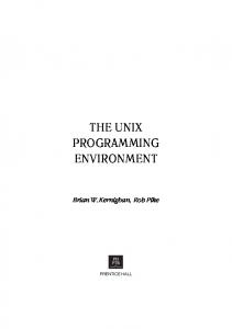
F i g u r e 5 - 3 : Part of the M P Specification of a naive parallel quicksort. T h i s is the Frame definition part of the recursive part of quicksort. T h e Read and Write operations are for the Bubble Sort Part. Figure 5-4 s h o w s the roadmap view of the program. This is the definition scoping view of MP. As each module is specified in the M P O E , the roadmap view is updated. T h e user can point to a part of the roadmap with the mouse and M P O E will automatically position the cursor at the corresponding point in the parse tree.
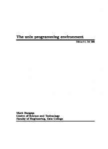
Figures 5-5, 5-6, and 5-7 s h o w the dynamic invocation tree indicating the processes invoking the tasks. Note the dynamic names of the MP entities as opposed to the static names in the roadmap view. In the first figure, a frame module has been highlighted indicating that it has been selected. As a result, another part of the display will s h o w the specifications associated with the selected frame.
24
26 April 1985 at 01:16
Time »
136397
m
QK
i
shared
Figu re 5-4:
T h e R o a d Map V i e w of Q u i c k s o r t
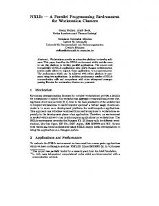
Figure 5-8 s h o w s a view of the frame usage g r a p h . This view s h o w s that at time 29733, one of the processes is accessing the frame. As time progresses, the view is updated a n d other processes and frames will be a d d e d . Frames are always placed o n the left and processes on the right. T H e view d o e s not indicate frames referencing other frames. Figure 5-9 is the process execution time bar g r a p h . S i n c e the application has b e e n implemented on a V a x 780 using a message-passing s c h e m e to simulate shared memory, the results are somewhat surprising. T h e times of n o system activity are d u e to the operating system o v e r h e a d initiating the processes and frames. T h e first recursive invocation of the task require a extraordinarily long time d u e to contention to the array. A s the execution continues, the data is almost all sorted and there are not as many references to it.
6. The Implementation Assistant T h e Implementation Assistant is the third P I E component.
T h e goals of the Implementation
Assistant are to provide semantic support in the parallel program development c y c l e . Specifically, the goals are: • Parallel program performance prediction before extensive implementation investments.
next prev i ous quit refresh zoo* select
P| n.e
PI
global
F i g u r e 5 - 5 : T h e Dynamic Invocation T r e e • A n Early V i e w
next previous quit refresh zooe ilcct
T i e e * 8487S
F i g u r e 5 - 8 : T h e Dynamic Invocation T r e e • A Latter V i e w
T i e e » 136397
r.
next previous quit refresh zoon select
J ? | ac.e
JFI
OK.9
>
>\ OK.9
HQ H shared
F i g u r e 5 - 7 : T h e Dynamic Invocation T r e e • A View Near Termination
26
26 April 1985 at 01:16
T i m « = 23733
t7| OFJ
g/nJ
q/9lobal
[P|q/H.e/qs/QK.e
fjjg/rl.e/qs/sharad [Pjq/H.e/q»/QK.l
P i g u r e 5 - 8 : A Frame U s a g e View
140009 q/n.0 q/n.e/gs/OK.e q/t1.9/q»/QK.l q/0.9/qs/QK.8/qs/Q>g-e q/H.e/qs/QK.9/qs/QK.l q/f1.e/q»/QK.l/qs/QIC.9 q/0.9/qs/QK.l/q«/QK.l yH.fl/g«/QK.9/qs/QtC.9/q«/QIC.0 Q
q/t1. 9/qs/QK. 9/qs/QK. 8 / q s / < * . 1
F i g u r e 5 - 9 : T h e Bar G r a p h View of Quicksort
26 April 1985 at 11:21
27
• Assist the user in choosing between implementations. • Semiautomatic parallel implementations.
program
generation
by
supporting
a set
of
well-defined
• Support for semiautomatic semantic instrumentation. • Support for a set of predefined representations related to the provided implementations.
A n implementation, in the context of a parallel program, is a specific way to d e c o m p o s e the parallel computation processes and data, as well as the way they are controlled.
Examples of parallel
implementations are: • Master-Slave • Recursive Master-Slave • Heap organized problem • Pipe-line • Systolic multi-dimensional pipe-line
T h e high level of abstraction of the implementation concept, allows one to characterize classes of problems by their relative performance/implementation measure. T h e performance/implementation ratio refers to the parallel application performance, w h e n implemented using two or more relevant implementations.
F o r example, a parallel program for a molecular dynamic problem could be
implemented as a Master-Slave or as a systolic pipe-line.
W h e n applying a parallel solution to the
problem, the user is interested in finding out what is the most suitable way to partition the problem data and d e c o m p o s e the computation in parallel processes, in the context of the architecture and operating systems of a specific parallel machine.
Encapsulating the knowledge pertinent to a set of frequently used implementations in the Implementation Assistant is, in our view, a first step toward fulfilling the a b o v e desiderata.
The
separation of c o n c e r n s between implementation and algorithm allows, aside from programming in the context of predefined implementation semantic knowledge, performance prediction before full program development. In this case, the performance d e b u g g i n g p r o c e s s is supported by providing specific representation per each implementation.
T h e implementation performance prediction step is supported in PIE by the iteration model [21, 22]. A n application is described in terms of its computation intensive and communication intensive
28
26 April 1985 at 11:21
behavior. T h e model allows the user to specify the p r o c e s s decomposition, the data partition a n d virtual parallel architecture characteristics. Currently, the model is limited to classes of application which are not heavily data dependent. A performance/implementation measure c o u l d be predicted per each relevant implementation. T h e user, assisted by an Implementation Discriminator, c o u l d then c h o o s e a suitable implementation. A s an implementation is c h o s e n , the p r e c e d e d structure (in terms of control, communication, synchronization, process decomposition and data partition) is made available to the user in the form of a modifiable template. U n d e r the assistance of a specific Template Assistant, the user can fill in the template or alter i t
From previous experience, w e infer that in most cases, the user will wish to
employ one of the provided implementations. F o r illustrating this c o n c e p t , consider an application to be implemented as a Unidirectional Pipeline ( U P L ) template. S u c h an environment will start by presenting the user with the U P L . M a s t e r template (see Figure 6-1) U P L . M a s t e r
Input Pipeline
Output Terminate
End UPL.Master Figu re 6-1:
T h e U P L . M a s t e r Implementation template
T h e components of the UPL.Master template are the pipeline processing n o d e s (Input, Pipeline, Output) and the termination condition agent. T h e terminating agent will indicate the processing n o d e in charge of the termination condition (with the default agent being the U s e r Interface). T h e UPL.Master template is controlled through a U P L oriented editor ( U P L O E ) .
T h e Pipeline
processing node could be split into multiple Pipeline processing nodes, e a c h o n e specifying different c o d e and a different replication count. U n d e r U P L O E control any one of the processing nodes template c o u l d be displayed. For example, Figure 6-2 s h o w s the template obtained by selecting a Pipeline processing node.
26 April 1985 at 11:21
29
P i p e l i n e
>body< receive.west
>body< send.east
>body< send . t e r m i n a t e
>body< End Pipeline Figure 6-2:
Pipeline Processing N o d e template
T h e Pipeline template provides send/receive operations to the process' adjacent neighbors and a send terminate communication with the terminate node. T h e user has to provide only the sequential application c o d e . O n c e all the nodes have been defined, the system wiJI automatically generate all the process management, memory management, synchronization, communication, instrumentation, and resource allocation required for the U P L implementation.
Moreover, the implementation being
semantically instrumented, specific representations relevant to the performance debugging of U P L are available at the user interface level.
In summary, by programming in the context of a preprogrammed template, the user expertise c o u l d be limited to its own application. T h e system is automatically generating most of the support required for parallelization of the application.
One
result in this context
preprogrammed semantic instrumentation support.
is the availability of
the
Implementation specific representations are
made available at both development-time and run-time.
T h e task of parallel programming and
performance debugging is greatly simplified and facilitated.
7. Status and Conclusions T h e issues of performance efficient parallel programs and system support for parallel programming are the main focus of the P I E system. T h e research method is pragmatic a n d is oriented toward practical results.
Currently, the P I E 1 phase is mostly d o n e and feasibility studies of the main
components are completed.
T h e MP Metalanguage has been defined.
T h e prototype
MP
Metalanguage System is currently supporting Pascal. Other languages are under consideration. T h e Program C o n s t r u c t o r components, namely the M P O E , the Status and Performance Monitor, and the
30
26 April 1985 at 11:21
Relational Representation System are in the prototype form a n d are experimentally operational.
Sample examples have been run through the P C T . and some of the results are presented in this paper. Observations from the running system show the performance bottlenecks, of the PIE1 system, to be located in the relational model and in the software monitoring. Accordingly, instead of using an available relational data base system ( I N G R E S as used in PIE1), w e are exploring the use of the relational model in ways specifically suited to P C T . O n e of the approaches under consideration is a memory resident relational model with optimization for often executed P C T relational operations. Related to the alleviation of the software monitoring performance bottleneck is the definition and the design of a "programmable general p u r p o s e multiprocessor architecture." T h i s multiprocessor, the Supercomputer W o r k b e n c h dedicates a large amount of hardware to the task of non-intrusive monitoring providing direct support for P C T and programming for observability.
T h e Implementation Assistant is currently in the feasibility study state. T h e performance predictor is operational.
T h e model c o v e r s applications w h i c h are not heavily data dependent.
Sample
implementation templates are under construction and and a set of templates with application to real-time processing have been evaluated. T h e c o n c e p t looks promising, h o w e v e r more flexibility in terms of conveying performance requirements to the system is required. Work employing production systems techniques to solve this problem has been started. Most of this work is the object of the s e c o n d research phase, i.e. P I E 4. In terms of the open and unsolved research issues in PIE, one of the main open problem is the use of formal specifications in the process of parallel program development. integrate formal specification programming environment.
for both
functionality
and
performance
A desideratum will be to requirements
into
the
T h e current state of art in this domain d o e s not provide enough of a
practical a p p r o a c h to enable us to c o n s i d e r the integration of s u c h techniques in PIE 1. A s e c o n d open question is how to provide support in P I E for different styles of programming languages s u c h as LISP and Prolog. This problem has not been explored in detail in P I E 1, and is being postponed to the PIE 4 design cycle. In PIE 1, the issue of what is the most suitable graphic interface has not been considered as the the main goal. It o u r belief that a lot more experimentation and user feedback is necessary in order to make a determination in this domain. Initial P I E 1 results, however, show that associating graphic presentations with the relational representations is attractive. In summary, this paper presents a s n a p s h o t of a relatively large research project on the move. A n overall programming environment structure reflecting the goals a n d the characteristics of parallel programs has been designed and implemented.
A set of c o n c e p t s have b e e n introduced and
26 April 1985 at 11:21
31
evaluated, including programming for observability, semantic monitoring, relational parallel program representation,
constraint
driven
abstract
data
types
(frames),
automatic
frame
unfolding,
programming with templates, and parallel implementation assistant. O u r initial results and feasibility studies are very encouraging.
8. Acknowledgment A research project having the goals and size of the P I E can s u c c e e d only by the cross-pollination of a group of talented researchers. T h e authors wish to acknowledge the contribution of the following researchers. Dalibor Vrsalovic has been responsible for the performance prediction model part of the Implementation Assistant, and the design of the User Interface; Robert Whiteside has been instrumental in providing the first version of the Relational Representation System; F r a n c e s c o Gregoretti has provided the first version of the Status and Performance Monitor; Beth Bottos has been responsible for the MP.Frames design; Eddie Caplan provided the implementation of the graphical User Interface. As part of her doctorial dissertation research, Beth Bottos will continue exploring the power of the constraint specifications as well as the automatic insertion of coordination c o d e to realize these constraints.
Apart from these specific contributions, we wish to acknowledge their
general contributions during numerous general designs PIE Project meetings.
Dan Siewiorek
deserves special acknowledgment for his continuous encouragement and wise suggestions.
26 April 1985 at 11:21
References [1]
Andler, S . Predicate Path E x p r e s s i o n s . In Principles of Programming Languages.
1979.
[2]
Archer, J . , and C o n w a y , R. COPE: A Cooperative Programming Environment. Technical Report TR81-459, Cornell University, J u n e , 1981.
[3]
B r i n c h - H a n s e n , P. Distributed Processes: A C o n c u r r e n t Programming C o n c e p t . Commun. ACM 21(11):934-941, November, 1978.
[4]
Campbell, R. H. Path Expressions: A Technique for Specifying Process Synchronization. T e c h n i c a l Report, University of Newcastle, August, 1976.
[5]
Deutsch, L. P. and Taft, E. A. Requirements for an Experimental CSL-80-10 edition, X e r o x , 1980.
[6]
Programming
Environment
Ellis, J . , Hooper, J . and J o h n s o n , T . An Architecture Description L a n g u a g e , A D L for Describing and Prototyping Distributed Systems. In System Science
Conference.
January, 1984.
[7]
Habermann, A. N. Path Expressions. T e c h n i c a l Report, Carnegie-Mellon University, J u n e , 1975.
[8]
Habermann, A. N. The Gandalf Research Project. Computer S c i e n c e R e s e a r c h Review, Carnegie-Mellon University, 1979.
[9]
Hoare, C. A . R. Monitors: A n Operating System Structuring C o n c e p t . Communications of the ACM 17(10):549-557, October, 1974.
[10]
J o n e s , Michael B., Richard F. Rashid, ary R. T h o m p s o n . Matchmaker: An Interface Specification L a n g u a g e for Distributed Processing. In Principles of Programming Languages, pages 225-235. A C M , J a n u a r y , 1985.
[11]
Kuck, D. J . , R. H. K u h n , D. A. Padua, B. Leasure, and M. Wolfe. D e p e n d e n c e G r a p h s and Compiler Optimizations. In Proc. of the 8th ACM Symp. on Principles
of Programming
Languages,
A C M , A C M , J a n u a r y , 1981. [12]
Kuck, D. J . , R. H. K u h n , B. Leasure, and M. Wolfe. T h e Structure of an A d v a n c e d Retargetable Vectorizer. Tutorial on Supercomputers: Design and Applications :168-178,1984.
pages 207-218.
8 J u l y 1983 at 06:57
[13]
Mitchell. J . G . , Maybury, W. and Sweet, R. Mesa Language Manual C S L - 7 9 - 3 edition, X e r o x , 1979.
[14]
O w i c k i , S . S . and Gries, D. A n Axiomatic Proof T e c h n i q u e for Parallel Programs. Acta Inform.
:319-340,1976.
[15]
O w i c k i , S . S . and Gries, D. Verifying Properties of Parallel Programs: A n Axiomatic A p p r o a c h . Commun. ACM 19(5):279-285, May, 1976.
[16]
Reiss, S . P. P E C A N : Program Development Systems T h a t S u p p o r t Multiple V i e w s . In Proceedings
of the Seventh
International
Conference
on Software
Engineering.
March,
1984. [17]
Segall, Z., S i n g h , A., S n o d g r a s s , R. T . , J o n e s , A. K. and Siewiorek, D. An Integrated Instrumentation Environment for Multiprocessors. In IEEE: Transactions on Computers. J a n u a r y , 1983.
[18]
S n o d g r a s s , R. Monitoring Distributed Systems: A Relational Approach. T e c h n i c a l Report, C a r n e g i e - M e l l o n University, December, 1982.
[19]
Snyder, L Introduction to the P o k e r Programming Environment. In Proceedings of the 1983 International Conference on Parallel Processing,
pages 289-92.
P u r d u e University, August, 1983. [20]
Teitelbaum, T . and R e p s , T . The Cornell Program Synthesizer:
A Syntax-Directed
Programming
Environment.
T e c h n i c a l Report T R 80-421, Cornell University, May, 1980. [21]
[22]
Vrsalovic, D., Siewiorek, D., Segall, Z . and G e h r i n g e r , E. Performance Prediction and Calibration for a Class of Multiprocessor T e c h n i c a l Report, C a r n e g i e - M e l l o n University, J u n e , 1984.
Systems.
Vrsalovic, D., G e h r i n g e r , E. F., Segall, Z . Z. a n d Siewiorek, D. P. T h e Influence of Parallel Decomposition Strategies on the Performance of Multiprocessor Systems. In The 12th Annual Symposium
on Computer
Architecture.
J u n e , 1985.