PINROB: A Portable API for Industrial Robots M. González Harbour1, R. Gómez Somarriba1, A. Strohmeier2 and J. Jacot2 1Departamento
de Electrónica y Computadores Universidad de Cantabria 39005 Santander, Spain email:
[email protected],
[email protected] 2Swiss
Federal Institute of Technology Department of Computer Science & Department of Micro-Engineering 1015 Lausanne, Switzerland email:
[email protected],
[email protected] Abstract: This paper describes a software architecture for industrial robots used in manufacturing equipment. In order to achieve software portability, the application software is dissociated from the low-level robot controller software. The interaction between these two pieces of software is achieved by a portable application programming interface (API) for industrial robots. We discuss the requirements for such an API, and propose a design called PINROB. Keywords: Robot, Manufacturing Cell, Production Cell, Robot Programming Language, Application Programming Interface, API, Software Portability, Ada.
1
Introduction
Industrial robots are in large use in manufacturing equipment. Production cells are designed around one or several robots. In a typical simple system, a robot sits in the middle of a cubicle surrounded by “peripherals”. One of the “peripherals” is usually a buffer store, containing pieces to be worked on, and the others are “dumb” machines. Their kinds depend on the manufacturing process: measuring and marking, assembly by gluing, insertion of parts, adjusting mechanical pieces, polishing, etc. Production cells are usually custom-made, the specifications being defined by the customer. Little design work is required to tailor the mechanical components to the intended use. The provider of the manufacturing cell is used to only a few number of robots, with the right physical characteristics, and the design and selection of the peripheral machines is largely based on past experience. However, the application software is usually developed from scratch, which is expensive, time-consuming and error prone. Software appears to be on the critical path of quality, but also for the time-to-thecustomer. It should be noticed that the customer in turn sometimes adapts the application software, with or without the help of the vendor. Up to three months might be needed for such an adaptive maintenance operation. The loss of the corresponding production cycles has a major negative impact on the profitability of the equipment.
1. Supported in part by the Comisión Interministerial de Ciencia y Tecnología of the Spanish Government under grant number TAP97-892
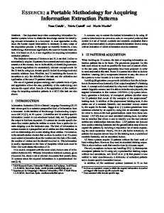
Robot Controller Application Program Special Language Interpreter
Robot Control Software Other RTS I/O & Specialized HW
CPU
Fig. 1. Layers in a Robot Computer System
The robot integrates a computer system (see Fig. 1), usually called a robot controller, which not only controls the robot, but also runs the application program specific to the production cell. The robot vendor provides all the hardware, but also the robot control software, and some kind of programming environment. This environment is usually built around a proprietary interpreted programming language. Technical details about the robot control software, especially the so-called servo loop, and other pieces of the run-time support system are not disclosed by the robot vendor to his customers. The robot control programming language varies therefore with the robot vendor (or the kind of robot controller), and also over time, because robot vendors improve constantly their programming languages. Production cell specialists explained us that all the robot control programming languages were very similar in purpose and functionality, but quite different in form. Different software development teams are therefore needed if several different robots are used. As in other fields of software, we thought it should be possible to use a single highlevel programming language, together with an application programming interface (API) for robots. Such an API would provide the basis for writing portable application programs. The purpose of this paper is to discuss the requirements and design of such a portable API, that we are currently implementing for several industrial robots. We call it PINROB, for Portable API for INdustrial ROBots. In a first step, we examined the following robot control programming languages: Adept V and V+ [3], Adept SILTOOLS [4], ABB-IRB 200 S3 programming language, ABB S4 Rapid programming language [2], AUTOMELEC Lucie [5], Siemens SIROTEC ACR-20 [10], and Demaurex Delta95 [6]. All of them support the normal programming language constructs such as conditional and loop statements, input and output statements, data types and variables, expressions and assignment. In addition, they provide robot-specific operations, such as the ability to move the robot to a particular point, or through a specified trajectory, or to read the position of the robot.
Some of these languages allow for some degree of multitasking, i.e. concurrent execution of different tasks or programs. We believe that the features to be considered in the API are basically the union of the features found in these robot controllers, rather than their intersection. Otherwise, all robots would become functionally alike, and any competitive advantage would be lost. The chosen approach implies that sometimes a feature cannot be implemented on a particular controller. In that case, we define the acceptable behaviour that the robot application must tolerate. We have chosen to use the Ada language as the programming language for the robot applications. In this way we can use all the normal constructs of a high-level language without having to implement them ourselves (such as data types, variables, expressions, conditional and loop statements, etc.). In addition, we can exploit the advantages of Ada over other standard languages, such as packaging in modules, data abstraction, encapsulation, object-oriented features, and well-defined real-time multitasking. What is missing is a set of robot-specific operations, similar to those of the robot programming languages, such as moving the robot to a particular point or reading its position. These operations together with the necessary data types are integrated into the PINROB API. It might appear that the Ada language is more difficult to learn and use than a conventional robot programming language. However, it is always possible to describe a small subset of the Ada language that, together with the robot API, would be no more complex than an average robot programming language. Of course, advanced programmers could always make use of all the advanced features of the Ada language.
2
Architecture of the Robot Programming Environment
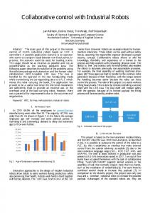
Because the robot controller is usually a special-purpose computer with a proprietary operating system, it is not possible to integrate Ada programs into it. Consequently, the programming environment that we have designed consists of an external computer linked to the robot controller through a communications channel (e.g. serial line or network). The application program written in Ada and using the PINROB interface runs in the external computer and sends commands to the robot controller. A command executive program written in the controller’s special-purpose language, and running in the robot controller, receives the commands, and interprets them. Then, if the command is a request to execute an action, it performs it by invoking the appropriate operations in the controller; if the command is a request for information about the robot, it obtains this information and returns it. Fig. 2 shows a diagram with the basic architecture. The execution of the robot application at one end and the subsequent execution of the associated commands at the controller end are synchronized by an acknowledge message that the command executive sends back for every command processed.
External Computer
Robot Controller
Application Program
nds
Command Executive Special Language Interpreter
Robot Control Software Other RTS
s
CPU
Statu
Operating System & Ada RTS
C o mm a
PINROB
I/O Devices
I/O & Specialized HW Serial Line
CPU
Fig. 2 Basic architecture of the robot programming environment
The advantages of this approach are that we reuse all the robot controller software without having to interact with internal aspects of its implementation. In addition, the remote computer can be any general-purpose computer, and both the robot application and most of the PINROB implementation will be portable. The non portable part of this architecture is the command executive, that has to be rewritten for every special controller, and part of the PINROB implementation.
3
Basic Requirements
The requirements for the PINROB API have been inspired by different robot programming languages. All the systems that we investigated were capable of controlling one robot with its arm and gripper, a control pendant keyboard and display used by the robot operator to program and supervise the robot operations, as well as digital input and output, analog input and output, and independent axes. In addition, some systems were capable of controlling several secondary robots, each with its arm and a gripper. Among the requirements, we have included the capability to control and monitor all of these objects. Some other systems have image processors, conveyor belts, welding tools, and many special tools that can be controlled from the controller. Since these are too systemspecific, we have not included them in the PINROB interface, although they can be included in particular systems as extensions. All of the robot controllers that we have checked have the capability to execute robot movement operations in parallel with instructions that use other objects such as digital or analog I/O, or the control pendant. We have required this behaviour as the default for the PINROB API, to increase the level of concurrency, which can then be exploited by the application program using Ada tasking. Also required are operations to synchronize the execution of the task controlling the robot movements with their finalization. In this way the program may be synchronized with the robot movements.
Another important requirement derived from most robot controllers is the ability to create “interrupt service routines” that are triggered by a digital input. In the PINROB API this is accomplished by requiring a Wait_Until_Signal operation, that blocks the calling task until a given digital line changes its state. In this way, that task itself becomes the “interrupt service routine”. In order to take full advantage of the learning capabilities of the robot (to learn about the position of objects, the size and orientation of its tools, etc.), we also require operations to read the values of variables defined in the robot controller. Another way of learning about positions of objects is accomplished through a requirement for the robot program to be able to stop temporarily, passing control to the robot controller. In this situation, the operator can move the robot to the desired position using the manual movement operations provided by the robot controller. Once the robot has been moved, the robot application program can resume its execution right after the point where it stopped. At that point, it can read the new position of the robot and store it for future reference. The requirements for the PINROB robot library [7] as well as the PINROB specification [8] are available from the authors upon request.
4
PINROB Software Architecture
One of the first design criteria for the robot library has been the simplicity of the interface, to make it easier for robot programmers to use it for writing robot application programs. We think that this is an extremely important criterion because if the interface is complex it will not be used. The simplicity criterion has driven us to avoid using advanced features of the Ada language. In this way, the interface is simpler to understand by robot programmers. Among such unused features, we can mention unconstrained data types, generics, and object-oriented features, such as inheritance and polymorphism. This limits the extension of the library in the sense that it will be necessary to recompile it and perhaps make slight changes to the applications when new features are added, but still we want to give more importance to simplicity. In the design of the architecture we have used encapsulation techniques to make the library interface implementation-independent. We have used private types for those data structures that are usually implemented in different ways in different robots (e.g. position frames). However, some other common data types have been defined as visible types because, traditionally, they are always used in the same way (e.g. joint coordinates as an array). We have also used the Ada 95 hierarchical library facility, to make the interface modular. However, we have kept the hierarchy to mostly two levels, in order to keep the simplicity. Fig. 3 shows the hierarchy of modules in the robot library.
Joints Legend Transformations Child Unit “with” dependency
Status Basic_Motion Location
PINROB
Speed_And_Accel Motion_Modifiers Special_Motion Tools
Gripper
Pendant Digital_IO Analog_IO Independent_Axes
Fig. 3 Hierarchy of the PINROB API
A short description of the modules of the robot library appears next. A complete description can be found in [8].
• PINROB: It is the parent unit of the robot library. It defines the basic data types, the elementary operations for these basic data types, the geometrical operations, and also defines all the exceptions that may be raised by the different operations of the robot library. The elementary data types used in addition to the predefined Ada data types are angle, angular speed, length, linear speed, weight, and robot identifier. Some arithmetic operations are provided to allow operations between some of the elementary data types (for example, angular speed times duration, returning angle). For geometry, PINROB specifies the data types cartesian position (X, Y, Z) and orientation (yaw, pitch, roll). In addition, it defines the type Frame that represents an absolute or relative position and orientation of an object in space. This type is defined as private, because different systems may prefer to use different representations of the orientation, such as yaw-pitch-roll or Euler angles. Operations are provided to build a frame from position and orientation data, and vice versa. In order to allow different coordinate systems and geometrical transformations, PINROB defines operations to calculate the absolute position of a position that is specified relative to a given coordinate system; to calculate the relative position, relative to a given coordinate system, of an absolute position; and to invert a relative position. These operations give PINROB full capabilities for
performing geometrical transformations and for using different coordinate systems. For example, this may be used to handle a robot that is upside-down and located at a particular point in space, or to manipulate objects whose coordinates are given relative to some particular frame.
• Joints: It defines the robot-dependent location data types, which are the joint coordinates and the robot configuration. The names of these types are portable, but their internal structures are robot-dependent. Operations are provided to set or retrieve the limits for each joint.
• Transformations: It defines the operations required to operate
robots with different coordinate basis, and different tools with different sizes. It also provides operations to perform direct and inverse transformations between the two basic location types: joint coordinates and frames.
• Status: The operations in this module allow the application to read the current status of the robot and the controller, attaching or detaching robots to or from the application program, setting and reading the power status of each robot, determining whether communications with the robot are OK or not, stopping the program temporarily to allow the robot controller to move the robot, and stopping the robot under a panic situation.
• Basic_Motion: It contains the operations that allow absolute or relative movements in straight-line, circle, or joint coordinates. All the motion instructions are asynchronous, i.e. the actual movement is performed concurrently with the execution of the program, up to a system-dependent number of pending movement operations. For each of the basic movement instructions there are two versions: one that accepts positions in joint coordinates, and one that accepts positions in frame units. The module also defines operations to allow the program to synchronize with the movement operations, by waiting until all the previously issued movement operations have been completed. Defer-movement operations are provided to specify an interval of time during which the robot movement needs to be stopped. The time interval may be fixed, or may depend on a signal condition (i.e. the state of a digital input). A Brake operation is provided to allow the application program to stop the robot, even if there are pending movement operations. Usually this operation is invoked after an abnormal condition. The Brake operation may be unconditional, or conditional depending upon a signal condition (i.e. the state of a digital input). In this latter case, the brake operation is asynchronous to the program.
• Location: It defines functions that allow the application program to read the robot’s current position or its current target position, in different units. The target position is the final position of the current movement instruction.
• Speed_and_Accel: It provides operations to set and read the different speed and acceleration factors that are used in all subsequent movement operations.
• Motion_Modifiers: The motion modifier operations allow the application program to manipulate and read the conditions under which other movement operations work. Continuous path enables a set of subsequent robot move operations to be considered as a continuous trajectory in which the robot does not stop at each point, but rather it approximates the trajectory to follow a smooth path between the different points. Continuous path may be broken explicitly, with the Disable_Continuous_Path operation, or implicitly (and only temporarily) with the instructions that require synchronization such as Wait_Until_Stopped. The stopping mode determines when a movement operation is considered to have been finished. There are different criteria to establish whether the robot is or not stopped, and operations are provided to specify the stopping mode desired by the application. Singular points are points in which the angular position of one or more joints may be arbitrary. Some systems provide different motion modes to deal with paths that come close to singular points, and thus operations are provided for the application to specify the desired behaviour. In some systems the servo control parameters may be adjusted to accommodate for different payloads, or different precision and force requirements. Consequently, this module defines operations that affect the servo control parameters. Finally, an operation is provided to adjust the advanced run setting, which allows the program to control the maximum number of simultaneously pending movement operations.
• Special_Motion: It defines operations that imply moving the robot to perform some special action. A special operation is provided for moving the robot in a single drive mode. A calibration move operation is necessary in some systems to initialize relative position encoders. In those systems in which this operation is not required, calibration move may be a null operation. This module also provides operations to change the robot configuration, which can be used when the target position of a movement is unreachable in the current configuration, or when movements in the current working area would become more comfortable.
• Tools: It defines the type Tool and its associated basic operations. This type is defined as a private type because different implementations may have different parameters associated with a tool. The operations associated with the tools are setting and reading its dimensions and weight. Other operations that control the tool are tool-dependent, and thus are not provided in this module.
• Gripper: The gripper operations initiate an action (open or close) on the gripper. This action starts after the last issued movement operation has been completed and it may proceed in parallel with the execution of the program and subsequent movement operations. If the system does not have a gripper attached, these operations fail silently.
• Pendant: Some robot applications may need to interact with a human operator. For example, the robot application may have to wait until the operator changes a tool in the robot and then presses a button. This kind of communication with a human operator is best accomplished through the control pendant. The pendant is
assumed to have a small display, and a keyboard. In addition, it may have other devices such as a potentiometer, joystick, or beeper. Operations are provided to control all such devices. In addition, there are functions to check for the presence of the pendant and of some of its devices.
• Digital_IO: Most controllers support digital I/O, and thus this module provides operations for reading from and writing to individual digital input or output lines, or ranges of them. It is also possible to wait for a digital input to reach a given state, or to set the outputs to default values. There are two interrogation functions to determine whether the system supports digital I/O, and whether it is concurrent with the program operation or not.
• Analog_IO: It defines operations for reading or setting analog inputs and outputs. • Independent_Axes: Some systems have one or more independent axes that may be moved independently of the robot without coordination with it. In other systems, independent axes may be moved in a coordinated motion with the robot. This module defines a constant that specifies how many independent axes are present. It also defines operations for moving an independent axis, reading its position, and moving one or more independent axes together with the robot in a coordinated manner.
5
Operating Procedures
Programming in the PINROB architecture is different than the usual approach with most industrial robots, because the language is not interpreted, but compiled. This means that the execution and debugging of the program need different approaches. Usually, when a robot operator is using a program, he or she uses the robot to learn the positions of the different objects it has to manipulate. These positions are stored into variables defined in the controller, which are then read and used by the program itself. In the PINROB environment, we can take a similar approach, but we must also program the learning phase into the application. We can define a number of variables, and ask the robot operator to move the robot manually, with the application program temporarily stopped, and store different robot positions into the variables defined. After this learning procedure finishes, the application program may continue at the point where it was stopped. Alternatively, if we do not wish to use robot variables, the position of the robot may be “learnt” by the application program, by invoking the Current_Position operation. Since the external computer used to program the robot is a general-purpose computer, it can have a nice windows-based user-interface, which can be used to implement userfriendly communication with the robot operator, during the learning or configuration phase, as well as for monitoring the robot during its productive operation. One of the advantages of interpreted robot programming languages is that debugging the program is very easy. The programmer can run the program step by step, or manually insert breakpoints (stop instructions) without having to recompile the
application. However, debugging technology for high-level language compilers is pretty mature, and thus we can use a conventional debugger to execute the Ada application program step by step, or manually insert breakpoints and read the values of variables. Of course, any modification of the program will require recompilation, but since the compiler will usually reside in the same machine as the Ada application, this should not represent any major difficulty.
6
Robot Application Example
In this section we will present a simple example of a typical robot application, to give a flavour of the PINROB interface and how it can be used. The system consists of a robot whose job is to pick up objects from a conveyor belt and put them in another one. Each object is picked up at a fixed position but, since it is moving, we use an optoelectronic sensor to determine when the object is ready to be picked up. This sensor is connected to digital input channel number one, which can be read by the application program. When the object is ready, the robot closes its gripper, moves up by 200 mm, and then moves in straight line to a point positioned 200 mm above the dropping position. There, the robot moves down by 200 mm and opens the gripper to drop the object. Finally, the robot moves back along the same trajectory to begin a new cycle. Table 1 shows the application code that performs this task. We can see that the application is self-configurable, because it includes operations to learn the positions of both the pick-up and the drop points, prior to the start of the normal operation cycles. This is achieved by making two calls to procedure Learn_Point, to learn each point. This procedure displays a message asking the operator to move the robot manually to the desired point, and then stops the program execution. When the operator resumes the application program, the current robot position is learnt. For convenience, before the two points are learnt, the robot’s orientation is changed to make the gripper point down. After the two points are learnt, the robot is moved to its initial position (200 mm above the pick-up point) and the gripper is opened. For the main cycle we select the continuous path mode, which does not require the robot to stop after every movement. We break continuous path temporarily both at the pick-up point and at the drop point, with the Wait_Until_Stopped command.
7
Conclusion and Future Work
In this paper we have shown the design of a portable API for industrial robots. This interface is based on the use of Ada as the robot programming language. It can be implemented on top of existing robot controllers from different manufacturers, and thus it provides for application program portability, which is not possible today because of the different programming languages used for each robot. We have described the main features of this API, and through a simple example we have shown that it is easy to use and yet very powerful. The use of the Ada language makes the
with PINROB, PINROB.Status, PINROB.Transformations, PINROB.Basic_Motion, PINROB.Speed_And_Accel, PINROB.Tools, PINROB.Tools.Gripper, PINROB.Motion_Modifiers, PINROB.Digital_IO, PINROB.Location, PINROB.Pendant; use PINROB; procedure Move_Objects is Pick_Up_Pos, Above_Pick_Up_Pos, Drop_Pos, Above_Drop_Pos : Frame; The_Tool :Tools.Tool:=Tools.Gripper.Gripper_Parameters; Height : constant Length := 200.0; -- millimeters Object_Ready: constant Digital_IO.Input_Channel:=1; Timeout : constant Duration:= 300.0; -- seconds Vertical : constant YPR_Orientation := (Yaw=> 0.0, Pitch=> 180.0, Roll=>0.0); procedure Learn_Point (Message: in String; Point : out Frame) is begin Pendant.Write_To_Display (Message); Status.Stop; -- The robot is now driven with the robot -- controller to the desired position Point:=Location.Current_Position; end Learn_Point; begin Status.Attach; Motion_Modifiers.Enable_Continuous_Path; Transformations.Set_Tool(The_Tool); Basic_Motion.Move_To (To_Frame( Position_Of(Location.Current_Position), Vertical)); Learn_Point("Drive robot to pick up position",Pick_Up_Pos); Learn_Point("Drive robot to drop position", Drop_Pos); Above_Pick_Up_Pos := Retract (Pick_Up_Pos, Height); Above_Drop_Pos := Retract (Drop_Pos, Height); Speed_And_Accel.Set_Linear_Speed_Factor (40.0); --percent Basic_Motion.Move_To (Above_Pick_Up_Pos); Tools.Gripper.Open; loop Basic_Motion.Move_To_Straight (Pick_Up_Pos); Basic_Motion.Wait_Until_Stopped; Digital_IO.Wait_Until_State (Object_Ready, Digital_IO.Asserted, Timeout); Tools.Gripper.Close; Basic_Motion.Move_To_Straight (Above_Pick_Up_Pos); Basic_Motion.Move_To_Straight (Above_Drop_Pos); Basic_Motion.Move_To_Straight (Drop_Pos); Basic_Motion.Wait_Until_Stopped; Tools.Gripper.Open; Basic_Motion.Move_To_Straight (Above_Drop_Pos); Basic_Motion.Move_To_Straight (Above_Pick_Up_Pos); end loop; end Move_Objects; Table 1. Moving objects from one conveyor belt to another one
application code almost self-explaining and the compiler helps in eliminating many programming errors. We are currently implementing PINROB for several robot controllers, including selfdeveloped robots as well as commercial ones. When these implementations are finished, we will know to what extent the API is portable. We also intend to translate production cell software into Ada and PINROB. The first goal is to assess the difficulty of the translation process. The second goal is to measure the time-behaviour of the new software. We will then port the Ada production cell software to a “foreign” robot in order to evaluate the level of portability of an application, rather than of the API.
Acknowledgements The authors would like to thank Mr. Fernando Gómez Estefanía, of Equipos Nucleares S.A., for his many contributions to the definition of the requirements of the PINROB API.
References [1]
A. Aasten, G. Elia, G. Menga. “G++: A Pattern Language for Computer Integrated Manufacturing”; Proceedings PLOPS'94, (J. Coplien and D. Schmidt, eds.), AddisonWesley, Reading, Mass., 1995, pp. 91-118.
[2]
ABB Robotics Products AB. “ABB S4 Rapid programming language. User’s Guide”.
[3]
Adept Technology Inc. “V and V+ Reference Guide”, Vol. 1/2, Version. 10.1, Oct. 1990.
[4]
Adept Technology Inc. “SILTOOLS Developer’s Guide.”, 1996.
[5]
AUTOMELEC. “Lucie. Description des Instructions.”
[6]
Demaurex. “Logiciel Delta95: Fonctionnalités de la couche haut niveau”, Version. 4.0.
[7]
M. González Harbour and A. Strohmeier. “Requirements for Portable API for Industrial Robots. Version 2.1”. Internal report, February 1998.
[8]
M. González Harbour and A. Strohmeier. “PINROB Specification. Version 2.1”. Internal report, February 1998.
[9]
H. A. Schmid. “Creating Applications from Components: A Manufacturing Framework Design” in IEEE Software, Nov. 1996, pp. 75.
[10] Siemens. “SIROTEC ACR-20. Software Version 4. Programming, parts 1-3”.