failure mechanisms can have different life distributions and acceleration models ..... 302, August. 1984. [ 111 Honda, K., Ohsawa, A., Toyokura, N., "Breakdown.
A Physics-of-failure (POF) Approach to Addressing Device Reliability in Accelerated Testing of MCMS
John Evans NASA Headquarters, Washington DC Michael J. Cushing, US Army Materiel Systems Analysis Activity, Aberdeen, MD Pradeep Lall, Motorola, Plantation FL Richard Bauernschub, CALCE-EPRC, University of Maryland, MD can be met in other ways." The solution is the physics-of-failure approach [28, 291 in which stresses target the potential failure mechanisms and reveal the suitability of a technology or design for a given application.
Abstract The physics-of-failure testing approach for multichip modules presented in this paper determines test levels based orn failure mechanisms, failure modes, and stresses for the application. It uses quantitative failure models and acceleration transforms, and adapts the knowledge of dominant failure mechanisms to the selection of accelerating stress parameters. The stress levels, designed specijically for each test article, are based on manufacturing processes, geometry, and materials.
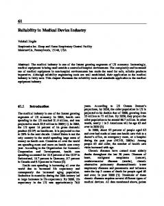
2: Approach Difficulties encountered in accelerated reliability testing of electronic products have limited its application and acceptance. Crucial, but difficult issues associated with the evaluation of accelerated reliability tests include: determination of the dominant failure mechanisms, determination of appropriate stress levels for accelerated tests, assessment of product reliability under intended lifecycle loads from data obtained under accelerated tests. One of the keys to the physics-of-failure acceleration modeling approach is the explicit treatment of failure processes or mechanisms. Separate treatment of failure mechanisms, a central feature of the physics-of-failure approach, is recommended by leading authorities on the accelerated reliability testing of electronic devices since failure mechanisms can have different life distributions and acceleration models (e.g., [25, 351). "Just as, in general, different failure mechanisms follow different life distributions, they may also have different acceleration models ...we can study each failure mode and mechanism separately ...This method is virtually the only way to do acceleration modeling successfully" [ 3 5 ] . Consider a microelectronic device which is subject to failure due to three dominant failure mechanisms acting at associated failure sites within the device. While the time to failure of each of the failure mechanisms may be influenced by changes in several parameters, including loads, geometries, material properties, defect magnitudes, and stresses, focus is placed on the impact of stress on time to failure. Figure 1 depicts the relationship between the time-to-failure distribution of each of the three failure
Keywords Physics of failure, accelerated testing, competing risks, electronics reliability, reliability testing.
1: Introduction To be competitive, electronic products must be mature when they first reach the market place. Because of the rapid pace of new product development, this objective has increased the need for accelerated tests to assess, demonstrate and improve component and subsystem reliability, certify components, detect failure modes, compare different manufacturers, and improve overall quality. Tests
and
screens
are
often
selected
from
govemment/military specifications such as MIL-STD-883. However, as noted by the US Air Force Rome Laboratory, in the January 1994 IEEE Reliability Society Newsletter, "Although manufacturers continue to use these screens today, most of the screens are impractical or need modifications for new technologies, and add little or no value for mature technologies. . . . With the defense budget/market declining, the DoD cannot afford costly test requirements that add little value to product quality or
14 0-8186-6970-5/94 $04.00 0 1994 IEEE
Time-To-Failure Distribution
results in a composite function appropriate for a nonrepairable electronic item or the time-to-first-failure of a repairable electronic system. Any reliability parameters of interest can be calculated from this composite function.
Acceleration Model
3: Accelerated test modeling
STRESS
STRESS
STRESS
Failure Mechanism 1
Failure Mechanism 2
Failure Mechanism 3
An accelerated test model is a mathematical equation used to relate the behavior of an item at one stress level to its behavior at another stress level. Models which are entirely based on curve fitting of test data are called empirical models. Models which describe behavior at the structural, or atomic level consistent with experimental results, are called physics-of-failure models.
Figure 1 Time to failure versus stress for a hypothetical microelectronic device
3.1: Model €ormulating PoF models characterize various degradation mechanisms operational in microelectronic devices. The degradation mechanisms include mechanical, electrical, and chemical degradation. The mechanical degradation mechanisms include thermal mismatches at mating interfaces, spatial temperature gradient, time-dependent temperature-change induced stresses, vibration, and mechanical shock stresses. Electrical degradation mechanisms include temperature, ionic contamination and charge anomaly induced parameter drifts including intrinsic carrier concentration, thermal voltage, mobility, current gain, leakage current, collector-emitter saturation voltage, and VTC shift for Bipolar Devices; and threshold voltage, mobility, drain current, time delay, strong inversion leakage, subthreshold leakage, and chip availability for MOSFET devices. Chemical degradation mechanisms include moisture and contamination-induced corrosion. In addition, ]mass-transfer degradation mechanisms involving electromigration, stress driven diffusive voiding, metallization migration, contact spiking, and hillock formation are also included. PoF models address potential degradation mechanisms in various package elements including the element attach, substrate, substrate attach, lead, lead seal, lid, lid seal, case, and interconnects. The mechanical, electrical and chemical degradation induced mechanisms can be (classified into wearout and overstress mechanisms. Wearout mechanisms address the time to failure under user-specified defect magnitudes due to the accumulation of damage, while overstress mechanisms address the failure of the component under the first application of the load. A representative sample of these models is given in table 1. In general, a typical failure model can be represented by
mechanisms, and the stress on which each mechanism depends. The failure mechanisms that cause hardware failures in electronic products generally do not have identical stress dependencies. For example, the temperature-stress dependencies of microelectronic failure mechanisms are known to vary considerably [28]. The relationship between the device time-to-failure and stress may be elusive unless failure mechanisms receive explicit treatment. Explicit consideration of dominant failure mechanisms, and their dependencies on loads, geometries and material properties, will provide the insight required to design and build reliability into electronic products, and compress reliability test time. The physics-of-failure accelerated test approach will include: Determine the likely failure mechanisms, based on current models for each potential failure mechanism. Include information on model applicability and limitations. Review the various stresses and their limits for the models of each failure mechanism in order to determine the accelerated stresses to be used in the test. During the test, perform a thorough failure analysis of each part, interconnection, etc. until the root-cause failure mechanism(s) is determined. Estimate model parameters for each failure mechanism using only failures due to that failure mechanism, treating failures due to other failure mechanisms as censoring times. Extrapolate down to use stress for each failure mechanism. Use the competing-risk model to combine the times-tofailure distributions, of the failure mechanisms. This
.
15
ailure mechanism Failure model equationheference lectromigration #lacks model [3]
Assumptions and range of validity Not valid for bamboo "-mer '"met structures; value of current tifmean = e-E,IKBT exponent is typical of Alj " 'para 1%Si metalization; current exponent and geometry Nhere tifmea,is the mean time to failure (hours), parameter value changes with wdmetis the metallization width (cm), material. Model assumes metallization open as failure is the metallization thickness (cm), mode; more Of sing'eApara is a parameter depending on sample geometry, physical :haracteristics of the film and substrate, and protective coating, layer metallization rather than multilayer metallizations i is the current density (A/cm2), where failure results in K , is the Boltzmann constant, resistance increase
.D.D.V.
.at0 and Niwa hodel 14, 261
t.If
K ~ 1T3
=
2o Df-gb
'-gb "-met1 'ol-atm
#here ti$ is the time to failure in seconds, T is the temperature in Kelvins, Dfagbis the grain-boundary diffusivity (mete?/sec), t-g, is the grain-boundary thickness (meter), V,,/bl-arm is the atomic volume for conductor atoms (meter3), o-metlis the stress in metallization, and 21 is the void separation DDB owler-Nordheim inneling model 18, 10, 4, 231
,,
s,k
('
cwa-iN
+
ti-ox,dn
= nprepxe
K~
(i
);3
_ _E
L--
K:(T
3;)
Nhere, ti-ox,bdis the time to breakdown, nPlexP is the room temperature value of the pre-exponential, i, is the electric field acceleration parameter, t-eflox is the effective oxide thickness E, is the activation energy, VWOx is the voltage across the oxide, CparaPintis an empirical factor determined experimentally, is the steady state operating temperature
xcessive itermetallics idsons model 5 , 30, 311
t=-
X2
2 Do e R T
Assumes plastic deformation due to passivation cooling occurs instantly; failure is assumed a function of diffusional relaxation
Charge build up at defects in oxides; breakdown of the oxide occurs when a critical charge density is reached in the oxide to trigger the breakdown process; defects are modeled as localized oxide thinning
Assumes parabolic diffusion law; has been shown to be valid for gold-aluminum bonds
where, t is the time to failure due to intermetallic formation, c is the critical intermetallic layer thickness, and r is the steady state operating temperature, 2 is the activation energy for intermetallics P is the rate constant
Table 1 A Representative Sample of the Models Used for PoF Approach
16
t&i,J) = F
m,,
m22 mZ3 ...
P31
P32
P33
edl
ed2
ed3
...
... ...
the life time of the product. Failure mechanisms which are most likely to result in device failure during mission life are then labelled the dominant failure mechanisms. Once the knowledge of the dominant field failure mechanisms has been obtained, the acceleration transforms relating the device life in operation to that in accelerated testing can be derived. Defect related reliability can then be addressed by screens derived by assessing the effects of the "worst case defect magnitudes" during accelerated tests. Allowable defect magnitudes are determined based on the sensitivity of the time-to-failure, due to potential failure mechanisms, from PoF models as follows:
(1)
___
For
j
=
k (3)
where ML is the mission life. The mathematical expression can be plotted as Figure 2 which shows the variability in life L, < L,