Permission to make digital/hard copy of all or part of this work for personal or classroom use is granted without fee provided that copies are not made or ...
Post-Layout Logic Restructuring for Performance Optimization Yi-Min Jiang Angela Krstic Kwang-Ting Cheng Malgorzata Marek-Sadowska Department of Electrical & Computer Engineering University of California, Santa Barbara, CA 93106
Abstract We propose a new methodology based on incremental logic restructuring for post-layout performance improvement. The new post-layout logic restructuring technique allows to use accurate interconnection delays for performance optimization, while the incremental nature of the technique guarantees convergence between logic synthesis and layout. The technique can be further integrated with other post-layout optimization techniques such as gate sizing and buffer insertion. Experimental results show that this technique combined with post-layout buffer insertion can achieve an additional 15% improvement in performance compared to designs produced by timing-driven logic optimization followed by pre-layout buffer insertion followed by timing-driven physical design. 1. Introduction Performance-driven logic synthesis followed by performance-driven layout [1] has become a necessity for designing high performance circuits. However, this loosely coupled two-phase timing optimization methodology has serious limitations for deep-submicron-based designs in which interconnection delays become the dominant factor in determining the circuit speed. Accurate information regarding the interconnection delays is not available during the logic synthesis phase and the interconnection delays are just roughly estimated in this phase. Therefore, errors in the estimation could result in a logic design far-off from an optimal one. Recently, an ATPG-based approach, named Redundancy Addition and Removal, was proposed for combinational and synchronous sequential logic optimization [3][4][5]. This approach optimizes the networks through iterative addition and removal of redundant connections. The redundancy addition and removal technique can identify alternative connections or gates for any given connection. For performance optimization, we can remove a connection on a critical path and replace it by one of its alternative connections/gates not on the critical path. Since *This work was supported by the National Science Foundation under grant MIP-9503651, California MICRO, SVR, and Mentor Graphics. 34th Design Automation Conference Permission to make digital/hard copy of all or part of this work for personal or classroom use is granted without fee provided that copies are not made or distributed for profit or commercial advantage, the copyright notice, the title of the publication and its date appear, and notice is given that copying is by permission of ACM, Inc. To copy otherwise, to republish, to post on servers or to redistribute to lists, requires prior specific permission and/or a fee. DAC 97, Anaheim, California 1997 ACM 0-89791-920-3/97/06 ..$3.50
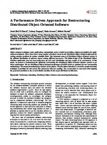
the layout of the design is available, routing for each alternative connection can be attempted and its interconnection delay can be accurately calculated. Therefore, good alternative connections/gates for replacement can be found in a greedy manner and the replacement can always achieve a real improvement of the circuit performance. In this paper, we apply the redundancy addition and removal technique for post-layout performance optimization. We further combine the technique with buffer insertion. The proposed method can be used to rectify designs produced by any synthesis tool that is driven by inaccurate cost functions. It allows the use of accurate interconnection delays for performance optimization and its incremental nature guarantees that the logic transformation can be physically implemented without changing the layout of the rest of the logic. We built a prototype system to implement the post-layout optimization process. The system consists of the Berkeley synthesis system SIS 1.2 [6], a commercial physical design system GARDS [7], and our programs for logic restructuring and for buffer tree insertion. The system has been tested for a suite of benchmark circuits. For each benchmark circuit, we generate a performance-optimized design using SIS 1.2 and GARDS. We then apply post-layout performance optimization using three different strategies: (1) using post-layout buffer insertion only, (2) using post-layout logic restructuring only and (3) using both logic restructuring and buffer insertion. For the 28 circuits we tested, we have observed, on average, an improvement of 6.6%, 7.6% and 15.4% respectively for these three strategies. Details of the experiments and the results are given in Section 3. This paper is organized as follows. In Section 2 we discuss how to apply this technique for post-layout performance optimization and how to combine it with the buffer insertion technique. Section 3 gives the details of implementation and experimental results on ISCAS89 and MCNC benchmark circuits. Section 4 concludes the paper. 2. Post-layout Performance Optimization Our proposed post-layout optimization process is shown in Figure 1. Initially, the logic is optimized and the buffers are inserted for performance optimization using the floorplan information. It is then followed by the performancedriven placement and routing. After the physical design phase, the interconnection delays are extracted and calculated, and timing-critical wires (wires on the critical paths) are identified using a static timing analyzer. A timing-criti-
Logic optimization and pre-layout buffer insertion for performance with floor-planning information
Performance-driven placement and routing Timing analysis Identify and select a set of timing-critical wires for performance improvement Identify alternative wires/logic for each target wire
(or build a buffer tree or select the best size for the driving gate)
Select the transformation with the highest benefit and modify the netlist
Incremental placement and routing Incremental timing analysis Consistent with prediction?
yes
no Backtrack Figure 1: The proposed overall design flow cal wire is then selected as a target wire for removal. We then use the redundancy addition and removal technique to identify the alternative wires/gates for the target-critical wire. The delay of each alternative wire/logic is estimated based on the current layout information. The best wire/logic in terms of the delay reduction in the critical paths is then selected for replacing the target timing-critical wire. Finally, the change is physically implemented by an incremental layout process which keeps the physical layout intact except for the target timing-critical wire and its alternative. The process iterates by finding another target timing-critical wires and it continues until no further timing improvement can be achieved. This process can incorporate other post-layout transformations such as gate sizing and buffer insertion. To reduce the delay of a selected timing-critical net, we can either simply remove it (by adding its alternative logic somewhere else), insert a buffer tree or resize its driving gate. All these possibilities can be enumerated and an estimate in delay reduction for each possible transformation can be derived based on current layout. It is possible that the transformation, after being implemented through incremental layout, does not meet the prediction and actually increases the delay of the circuit. In such a case, the process backtracks, restores the netlist and layout to that of before the modification and selects the transformation with the next highest estimated benefit to modify the circuit. If the circuit performance is indeed improved or at least not degraded, the timing analyzer updates the list of timing-critical paths for the next iteration. The process continues until all candidate transformations in an iteration either have negative estimated benefits or have been tried and backtracked. Two issues need to be addressed in order to successfully apply the technique for post-layout logic optimization: (1) A design may have a large number of timing-critical paths
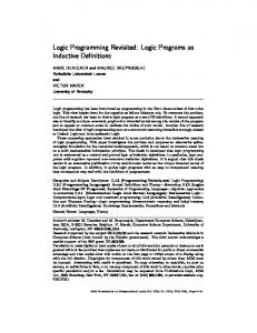
and thus a large number of timing-critical wires. We need to develop a strategy for determining which nets to target and their order for processing and removal. (2) A given target wire might have many alternatives. The selection of an alternative wire for replacement of the given wire can also substantially affect the final results. In the following we discuss these problems in more detail and describe our solutions to them. 2.1 Selecting timing-critical wires for removal and alternative wires for addition A wire w = gi→gj is called a candidate wire if it is on a timing-critical path of the circuit. We say that logic l consisting of one or more wires and/or gates is an alternative logic for wire w if the addition of logic l, together with the removal of wire w, does not change the function of any of the outputs of the circuit. A pair (w, l) is said to be a candidate pair if w is a candidate wire and l is an alternative logic for w. We consider the path with the longest delay as a timing-critical path. We use a static timing analyzer to identify a set of timing-critical paths. A subset of wires contained in the critical paths are considered as candidate wires. Each candidate wire may have more than one alternative logic. Therefore, there is a set of candidate pairs. Our goal is to identify a candidate pair among the set such that, after the transformation is performed, the performance of the circuit improves the most. Adding and removing redundancy changes the logic structure and the timing information in the circuit. Let the candidate wire for removal be wr = gi→gj and let wire wa = gm→gn be its alternative wire as shown in Figure 2. The fanout cones of these four gates are as indicated. to be removed g
i
g
j
to be added g
m
g
n
Figure 2: Regions of signals affected by redundancy addition and removal
Removal of the candidate wire results in the removal of the target critical path and a number of other paths. The load of gate gi decreases and therefore, the arrival times of gates in the fanout cone of gate gi may change (i.e., the delays of all remaining paths that contain gate gi decrease). On the other hand, addition of the alternative wire gm→gn, results in a number of paths being added into the circuit. The logic function of all internal gates in the fanout cone of the gate gn may change. The load of the gate gm increases and that affects the arrival times of the gates in the fanout cone of the gate gm. The discussion can be easily generalized for cases when gates, instead of wires, are added. Since in the transformation selection phase the alternative connections/gates are not physically implemented, we estimate the delay of the added logic based on the current
layout information. Once an estimated delay of the alternative wire is derived, incremental timing analysis which examines only the nodes in the fanout cones of the associated gates can derive an estimated delay of the circuit after the transformation. The alternative wire/logic may need to be added in a congested area where it cannot not be properly placed and routed. A parameter indicating the degree of congestion of a target area can be directly derived by the physical design tool we use [7]. We set a threshold value to exclude some candidate transformations. If the congestion parameter of the area of the alternative wire/logic is greater than the threshold, we remove the corresponding candidate transformation from the candidate list. Modifying the circuit based on a candidate pair may affect many other paths in addition to the targeted timingcritical path. The impact on other long paths should also be considered in the cost function for selecting the best candidate pair. We define the benefit function of a candidate pair (w,l) as follows: benefit(w,l) = gain(w,l) + α ✽ secondary_gain(w,l) (1) The gain of a candidate pair (w,l) is defined as the reduction of the circuit delay obtained by replacing the candidate wire w with its alternative logic l. The secondary_gain of (w,l) is the delay reduction of the n longest paths by the transformation where n is a program parameter. A secondary_gain(w,l) which reflects the delay reductions with respect to a subset of long paths gives guidance for selection. In our experiment, n is chosen as 5. The weighting constant α is a small number which is assigned as 0.1 in our experiment. The benefit function is computed for each candidate pair and the one with the highest value is selected for implementation. 2.2 Combining redundancy addition and removal with buffer insertion In the transformation selection phase, in addition to considering the candidate pairs, we can also consider inserting buffer trees at the timing-critical nets or sizing their driving gates. These three types of transformations are significantly different in nature. Therefore, combining them would allow exploring a larger design space and lead to better results - this could particularly be true under the greedy strategy used in our iterative process. In this paper, we choose to include buffer insertion only to illustrate that multiple types of transformations can be easily integrated into our post-layout optimization process. For each timing-critical net, we consider inserting a kary balance tree [2] - the number of fanouts of each node in the tree is k except for the leaf nodes. We use the delay equation proposed in [2] to estimate the delay from the source node to each of the leaf nodes after the buffer tree is inserted. If a buffer insertion transformation has the highest benefit among all candidate transformations considered, we construct the buffer tree for final implementation.
3. Implementation and Experimental Results In this section, we discuss some implementation issues and present experimental results for ISCAS89 and MCNC benchmark circuits. We use the SIS-1.2 package [6] for logic optimization and GARDS [7] for layout. For logic optimization, script script.delay is applied followed by pre-layout buffer insertion buffer_opt to optimize the circuit for performance at the logic level. For physical design, we use a 0.55 µm CMOS library and GARDS [20] - a physical design system for gate arrays design. We use the performance-driven option in GARDS for performance-driven placement and routing. After physical design, we further use GARDS to extract the RC-trees of the interconnects and calculate the interconnect delays for timing analysis. For each circuit, we follow the algorithm shown in Figure 1 for post-layout performance optimization. In order to evaluate the redundancy addition and removal technique and the value of combining it with the buffer insertion technique for post-layout optimization, three different strategies are used: (1) buffer insertion only, (2) redundancy addition and removal only and (3) combining both buffer insertion and redundancy addition and removal. Once a post-layout transformation is identified (either replacing a wire with its alternative logic or inserting a buffer tree to a net), we use the Engineering Change Orders (ECO’s) feature of GARDS to implement the transformation. It tries to keep the layout of the unmodified logic intact, and only re-place and re-route the modified part of the circuit. The router used in GARDS is an area router which makes incremental change of routing possible. The results for the 12 largest ISCAS89 sequential benchmark circuits and 14 largest MCNC combinational benchmark circuits are summarized in Tables 1 and 2. The delays of the longest paths for circuits optimized by SIS with script.delay and buffer_opt followed by GARDS for timing-driven layout are shown in Column 2. The interconnect delays used for timing analysis are computed by GARDS using the extracted RC-trees. Columns 3-6, 7-10 and 11-14 shows the results of (1) using buffer insertion alone, (2) using redundancy addition and removal alone and (3) using the combination of buffer insertion and redundancy addition and removal. For each experiment, we record the critical path delay of the final design, the percentage of reduction of critical path delay, the number of iterations and the total runtime of post-layout optimization. Post-layout buffer insertion reduces the critical path delays, on average, by 5.8% and 7.4% respectively for the two sets of benchmark circuits. Redundancy addition and removal reduces them by 7.6% and 7.6% respectively which is just slightly better than the buffer insertion technique. When these two techniques are combined, 15.3% and 15.4% reductions are achieved which are even greater than the sum of the reduction achieved by each individual technique. These results indicate that these two post-layout
Table 1: Experimental results for ISCAS89 benchmark circuits
Ckt.
s1196 s1238 s1423 s1488 s1494 s5378 s9234 s13207 s15850 s35932 s38417 s38584 average
delay of longest path(timingdriven SIS + GARDS)(ns)
Post-layout performance optimization
delay(ns)
red. (%)
# of ite.
runtime
delay(ns)
red. (%)
# of ite.
runtime
delay(ns)
red. (%)
# of ite.
runtime
16.4 21.4 24.1 18.9 22.1 13.9 17.9 27.5 30.8 41.2 40.4 43.5 -
15.1 20.4 23.6 18.9 18.6 13.9 17.0 25.8 28.8 38.7 37.1 40.5 -
7.9 4.7 2.1 0.0 15.8 0.0 5.0 6.2 6.5 6.1 8.2 6.9 5.8
2 4 5 5 7 5 3 6 8 9 7 6 6
9m 12 m 17 m 20 m 30 m 17 m 30 m 85 m 125 m 208 m 135 m 150 m -
15.5 20.1 23.1 16.5 19.1 12.5 17.1 26.1 27.9 39.1 36.4 41.2 -
5.5 6.1 4.1 12.7 13.6 10.1 4.5 5.1 9.4 5.1 9.9 5.3 7.6
3 12 11 10 16 5 5 9 14 11 10 7 9
16 m 42 m 30 m 30 m 64 m 78 m 32 m 108 m 275 m 260 m 208 m 233 m -
14.0 17.7 22.8 13.8 16.4 12.0 15.9 24.1 25.9 36.5 33.8 37.4 -
14.6 17.3 5.4 27.0 25.8 13.7 11.2 12.4 15.9 11.4 16.3 14.0 15.4
5 8 15 12 11 9 7 12 11 13 10 8 10
23 m 31 m 38 m 35 m 41 m 151 m 40 m 145 m 216 m 316 m 200 m 283 m -
Buffer insertion
red. addition and removal
red. addition and removal + buffer insertion
Table 2: Experimental results for MCNC benchmark circuits
Ckt.
k2 x3 rot sct vda x1 apex6 c1355 c1908 c2670 c3540 c5315 c6288 c7552 average
delay of longest path(timingdriven SIS + GARDS)(ns)
Post-layout performance optimization
delay(ns)
red. (%)
# of ite.
runtime
delay(ns)
red. (%)
# of ite.
runtime
delay(ns)
red. (%)
# of ite.
runtime
22.0 9.2 17.9 6.2 17.2 10.7 12.5 18.6 24.1 22.7 32.3 38.9 53.4 46.5 -
20.3 8.5 17.9 5.1 16.1 9.6 11.6 17.4 23.0 21.0 28.8 36.7 50.3 44.0 -
7.7 7.6 0.0 17.7 6.4 10.3 7.2 6.5 4.6 7.5 10.8 5.7 5.8 5.4 7.4
8 2 2 4 4 3 3 4 6 5 7 10 7 10 5
43 m 5m 2m 4m 10 m 5m 4m 16 m 19 m 29 m 49 m 36 m 85 m 86 m -
20.9 8.8 15.2 4.9 15.9 9.7 11.9 17.6 23.3 21.6 29.4 36.2 51.8 43.6 -
5.0 4.3 15.1 21.0 7.6 9.3 4.8 5.4 3.3 4.8 9.0 6.9 3.1 6.2 7.6
10 2 7 8 7 6 5 7 3 10 9 15 17 17 9
50 m 6m 13 m 8m 15 m 8m 5m 27 m 13 m 53 m 58 m 66 m 141 m 178 m -
18.3 7.9 14.9 4.3 15.0 8.8 9.1 17.0 21.9 21.0 26.3 34.2 47.1 41.5 -
16.8 14.1 16.8 30.6 12.8 17.8 27.2 8.6 9.1 7.5 18.6 12.1 11.8 10.7 15.3
12 2 6 5 9 5 3 8 12 7 11 18 24 15 10
58 m 6m 11 m 4m 20 m 7m 4m 29 m 27 m 38 m 61 m 72 m 170 m 148 m -
Buffer insertion
red. addition and removal
transformations are complementing each other. The results also indicate that the redundancy addition and removal technique and the combined technique require more iterations and therefore take longer CPU runtimes. The CPU runtimes shown in the tables include the runtimes for all post-layout processes including incremental layout (through ECO of GARDS), timing analysis and logic transformation identification/selection. 4. Conclusion We propose an incremental logic restructuring technique for post-layout performance optimization. Using the accurate interconnection delays extracted from layout, critical nets are identified, removed and replaced by its alternative logic. The modifications are then physically implemented through incremental layout. The incremental nature of our technique ensures the convergence between logic synthesis and layout. The technique can be further integrated with other post-layout optimization techniques such as gate sizing and buffer insertion. We have built a prototype system and tested a wide range of benchmark circuits to evaluate the effectiveness of the technique. We have demonstrated that the technique is complementary to the buffer insertion technique. By combining buffer insertion and the new logic restructuring technique, another 15% improvement on performance can be achieved for designs already timing-opti-
red. addition and removal + buffer insertion
mized by synthesis and layout tools. We are currently investigating more logic transformations which are suitable in the post-layout phase. References [1] M. Marek-Sadowska, “Issues in Timing Driven Layout,” in Algorithmic Aspects of VLSI Layout, Edited by M. Sarrafzadeh and D. T. Lee, World Scientific Publishing Co., 1993. [2] R. J. Carragher, M. Fujita, and C. K. Cheng, “Simple Tree-Construction Heuristics for the Fanout Problem,” Proceedings of International Conference on Computer-Aided Design, pp. 671679, November 1995. [3] K.-T. Cheng and L. A. Entrena, “Multi-Level Logic Optimization by Redundancy Addition and Removal,” Proceedings of European Design Automation Conference, pp. 373-377, February 1993. [4] L. A. Entrena and K.-T. Cheng, “Sequential Logic Optimization by Redundancy Addition and Removal,” IEEE Transactions on CAD, vol. 14, no. 7, pp. 909-916, July 1995. [5] S.-C. Chang, M. Marek-Sadowska, and K.-T. Cheng, “Perturb and Simplify: Multi-level Boolean Network Optimizer,” IEEE Transactions on CAD, vol. 15, no. 12, pp. 1494-1504, December 1996. [6] “SIS: A System for Sequential Circuit Synthesis,” Report M92/ 41, University of California, Berkeley, May 1992. [7] GARDS, “Command Reference Manual,” Volume 1-4, Silicon Valley Research, September 1996.