in comparison to a similar network using omnidirectional an- tennas. This is ... protocol provides no benefits in the spatial reuse of the wireless channel. However ...
TO APPEAR IN THE PROC. OF IEEE INTER. CONF. ON COMP. COMM. AND NETWORKING (IC3N’02)
1
Power Consumption and Throughput in Mobile Ad Hoc Networks using Directional Antennas Asis Nasipuri, Kai Li and Uma Reddy Sappidi Department of Electrical & Computer Engineering The University of North Carolina at Charlotte Charlotte, NC 28223-0001, U.S.A. Email: {anasipur,kli,ursappid}@uncc.edu
Abstract— We present medium access control (MAC) protocols for mobile ad hoc networks that utilize directional antennas. The use of directional antennas in place of traditional omnidirectional antennas reduces interference and thereby improves the throughput performance of the network. An additional advantage of using directional antennas is due to its higher gain from its directivity, which can be utilized to reduce the transmission power during a directional transmission. In order to maximally utilize the savings in the average power consumption in the network, we propose a power control scheme that maintains a minimum transmission power level for effective transmission of packets using directional antennas. We present simulation results showing the throughput advantage and the savings in the average consumed power in the network using the proposed protocol. We also present results showing the maximum possible savings in power consumption in the same network when an ideal power control scheme is applied.
I. I NTRODUCTION Directional antennas are traditionally used in cellular wireless networks to increase the network capacity [15]. A cellular system using directional base station antennas can have a smaller distance between co-channel cells than a system using omnidirectional antennas, thereby achieving a higher degree of spatial reuse of spectrum. Mobile ad hoc networks can potentially gain similar capacity advantages by using directional antennas. However, since ad hoc networks use peer-to-peer transmissions, the mechanism for using directional antennas in these networks is more complicated than in cellular networks where directional antennas are only used in static base stations. A mobile terminal in an ad hoc network may need to transmit to any other node that is within its range. Since all nodes are mobile, in order to use directional antennas for communication the nodes need to dynamically estimate the direction of its neighbors and also follow an efficient protocol for orienting its direction for transmission and reception. Nevertheless, since most of the data transmission in an ad hoc network is unicast, there has been a lot of interest in recent years to apply the usage of directional antennas to isolate independent transmissions in the network and thereby increase the network throughput [6], [11], [14], [3], [16]. In addition to the advantage of reducing unwanted interference, directional antennas have the property that its peak gain
is higher than that of a similar antenna with an omnidirectional pattern. This characteristic can be utilized to reduce the power of a transmitter when it is using a directional antenna. We show that a MAC protocol that utilizes directional antennas effectively and controls its transmit power adequately, can provide a better throughput as well as reduce the power consumption in comparison to a similar network using omnidirectional antennas. This is important, as the mobile terminals in an ad hoc network usually have limited energy resources. In this paper we focus on adaptations of the IEEE 802.11 MAC protocol so as to obtain practical solutions to the following: finding the directions for transmission and reception at mobile nodes, designing appropriate transmission and reception strategies for the MAC control packets to minimize interference amongst distinct pairs of communicating nodes, and implementing power control for data transmission for conserving power. We present performance evaluations that methodically analyze the effects of various adaptation policies and finally present a protocol that attains the maximum benefits from all the policies considered. The paper is organized as follows. We present some related work on medium access control using directional antennas in section II. The system model and concepts related to medium access in ad hoc networks that motivate the proposed ideas are presented in section III. Details of some of the MAC protocols using these ideas are presented in section IV. We present performance evaluations of the proposed protocols from computer simulations in section V. Conclusions of our work are presented in section VI. II. R ELATED W ORK The possibility of benefiting from directional transmissions in packet radio networks was first proposed in [17], where a slotted ALOHA packet radio network was considered. Thereafter, several studies were presented on designing MAC protocols for using sectorized and beamforming directional antennas in mobile ad hoc networks. Protocols presented in [6] use the exchange of RTS (“request-to-send”) and CTS (“clear-tosend”) packets [5] to block neighboring nodes from transmitting in directions that would interfere with an intended directional data transmission while allowing them to transmit on
TO APPEAR IN THE PROC. OF IEEE INTER. CONF. ON COMP. COMM. AND NETWORKING (IC3N’02)
other directions. The authors assume that the direction for transmission is determined using location information, which is obtained with additional hardware such as a GPS. In [11] a mechanism for determining the direction of a transmitting node from signal strength measurements was presented, which eliminates the need for GPS receivers at every node. There, the MAC protocol used omnidirectional RTS and CTS packets, allowing the corresponding recipients to determine the directions of the transmitters. These directions were then used for directional transmission and reception of the data packet. Because of omnidirectional transmission of RTS and CTS packets, this protocol provides no benefits in the spatial reuse of the wireless channel. However, it still improves the throughput over a MAC using omnidirectional antennas due to the reduced amount of interference caused by the directional data transmission. More recently, the protocol presented in [7] considers that virtual carrier sensing using the RTS and CTS exchange be performed on a sector by sector basis rather than on a traditional omnidirectional basis. According to their scheme, the network allocation vector (NAV) is maintained separately in each sector (directional NAV), allowing immediate transmission of control packets on those sectors which are clear instead of having to defer the transmission until it is safe to transmit on all sectors at the same time. The use of more advanced beamforming antennas in place of sectorized directional antennas in ad hoc networks is considered in [14]. The authors assume prior knowledge of location information and use directional transmission of RTS and CTS packets. They presented the study of two collision avoidance schemes, one being more aggressive than the other, for blocking transmissions from listening nodes that receive an RTS or a CTS packet. The concept of directional NAV is also considered in [3], where beamforming antennas are used. They also consider directional transmissions of RTS and CTS packets with prior knowledge of node locations. The authors identify some problems with this basic directional virtual carrier sensing scheme and propose a multihop RTS protocol, where the additional gain of the directional antenna is utilized to transmit data packets to a receiver that cannot be reached by omnidirectional antennas but can be reached with directional antennas. III. P RELIMINARIES A. Directional antennas Typically the gain of an antenna is described as a function of the horizontal angle θ and the vertical angle φ from a fixed line of reference. For an omnidirectional antenna, the gain is invariant with respect to the angle θ, whereas a directional antenna has a higher gain for a range of values of θ known as the main lobe, and lower gain in other directions. Antennas used in terrestrial wireless communication usually have a vertical beam pattern lying within a certain range of values of φ close to the horizontal plane that is identical for all values of θ. The beamwidth of a directional antenna is described as the horizontal angular variation (variation of θ) within which the gain of the antenna is not lower than 3 dB of the maximum gain
2
of the antenna. For a sectorized antenna, this beam is oriented towards a fixed direction. The more expensive beamforming antennas can steer or switch the direction as well as the directivity of the main lobe as desired using electronic control. The peak gain of a directional antenna usually increases with its directivity. This implies that the peak gain of an antenna with a narrow beamwidth will be higher than that of a similar antenna having a larger beamwidth. B. IEEE 802.11 MAC The IEEE 802.11 MAC protocol [4] was designed to function with omnidirectional transmissions. It uses carrier sense multiple access with collision avoidance (CSMA/CA) along with the option of the exchange of RTS and CTS control packets to perform virtual carrier sensing before transmission of data. The basic CSMA/CA scheme dictates that each node needing to transmit a packet must wait until it finds the channel idle for a random amount of time as determined by its backoff timer. This avoids collisions amongst neighboring nodes who sense the channel similarly. However, since this mechanism does not avoid collisions with transmissions from hidden terminals, the option of RTS/CTS handshaking may be used. The transmission of an RTS packet causes all nodes that receive the RTS to go off-the-air (OTA) until the CTS packet is received. The OTA wait periods are maintained in the NAV variable of the IEEE 802.11 MAC. This variable is updated using information from the duration field of every packet received by the node. Similarly, all nodes that receive the CTS packet observe an OTA wait period before they transmit. If an RTS is transmitted while the channel is busy near the destination, it is not received and the source will timeout and send the RTS packet again. C. Throughput considerations The throughput in a mobile ad hoc network primarily depends on two factors: (a) the effectiveness by which the source nodes gain access to the channel, and (b) the corresponding signal-to-interference-plus-noise ratio (SINR) at the receiver. The use of directional antennas can potentially provide benefits on both these accounts. When carrier sensing (either physical or virtual) is performed in a specific direction, the possibility of finding the channel free is higher. For instance, consider that nodes A and B in Figure 1 are communicating using directional antennas, where C A and CB represent the areas covered by the directional antennas used by A and B, respectively. Here, nodes C and D, which do not lie in C A or CB , will be able to gain access to the channel. Moreover, node E can access the channel for transmission in a direction away from A and B, such as C E . However, if A and B were to use omnidirectional antennas, C, D, and E would need to observe OTA wait periods before they can transmit. The issues concerning the SINR of a packet are somewhat more complex. A wireless signal suffers a variety of degrading effects during propagation, which includes path loss, shadowing, and multipath reflections from surrounding objects. As a result, the average power a wireless signal decays exponentially
TO APPEAR IN THE PROC. OF IEEE INTER. CONF. ON COMP. COMM. AND NETWORKING (IC3N’02)
CE CB
CA
E A
C
Fig. 1. work.
B
D
Example of directional transmission and reception in an ad hoc net-
with distance and the envelope of the received signal experiences random fading. Node mobility and multipath reflections also cause the received signal to vary with time. The probability of correctly detecting a received packet depends on the ratio of the signal power of the packet over the total noise and interference power received at the destination from all other transmitters in the network. When the SINR of a received packet falls below a minimum threshold SIR min (which depends on the communication technology), the packet cannot be correctly detected and is considered to have suffered a “collision”. The transmission range of a node is determined by the maximum distance at which a transmitted packet can be received by another similar node in the absence of any interference. This implies that within the radio range of the transmitter only the signal-to-noise ratio (SNR) will exceed the SIR min threshold. Potentially any other transmission in the network, even if it is transmitted from a node lying beyond the radio range from the receiver, can cause a collision if the SINR of the received packet falls below SIR min . Carrier sensing tries to avoid collisions by confirming that the power of the interfering signal (carrier power) lies below a threshold CS thresh , before the packet is transmitted. However, since carrier sensing can only be done at the transmitter where the interference power is different from that at the receiver, it cannot correctly predict whether the SINR for a specific transmitted packet will exceed the SIRmin threshold at the receiver. The RTS-CTS exchange is a good way to circumvent these shortcomings of carrier sensing in wireless networks. However, there are two major concerns with the effectiveness of the RTS-CTS based reservation mechanism. Firstly, collisions between these control packets can cause the method to fail. For instance, a hidden terminal can miss a CTS packet due to a collision from another control packet and can disrupt the subsequent data packet reception. Secondly, the control packets create additional channel overhead, which reduces the channel utilization. Based on the above discussion it should be clear that reduction of overall interference is a key factor for improving the packet success probability in ad hoc networks. A transmission from a directional antenna reduces interference to all nodes outside of its main lobe. Directional antennas used in reception reduce unwanted interference from surrounding transmitters. Overall, this leads to a higher SINR value for the packet being received, and hence increases the network throughput.
3
D. Transmit power issues Since a directional antenna has a higher gain, a transmitter using directional antennas requires a lower amount of power to transmit to the same distance as would be needed with an omnidirectional antenna. Hence, transmitting nodes can conserve power by adequately reducing the transmit power when using directional transmissions. In this paper, we assume that for a given transmission distance, the power required by a transmitter using a directional antenna is proportional to its beamwidth. This implies that a source using a directional antenna with 90 0 beamwidth will require 1/4 the amount of power as that needed with an omnidirectional antenna to transmit to the same destination. Note that the gain of a directional antenna should also be taken into account for receiving and carrier sensing with directional antennas. However, we do not consider the power consumed for these receiver operations in this work. We assume that nodes automatically control the transmit power when using a directional antenna such that the transmission distance is maintained constant. Furthermore, we also consider a power control scheme, where the transmission power is reduced by an additional factor that is based on the minimum SINR required at the destination. This will be discussed later. IV. M EDIUM ACCESS C ONTROL USING D IRECTIONAL A NTENNAS In this section we analyze various adaptations to the IEEE 802.11 MAC for use with directional antennas at the mobile nodes in order to achieve two benefits: a higher throughput, and savings in power consumption. For our discussion, we assume that each node is equipped with an array of N non-overlapping sectorized antennas covering all angles as depicted in Figure 2. The sectorized antennas in different nodes may be oriented differently as the mobile nodes have no way of fixing their antenna directions with respect to one another. There is no separate hardware to detect node locations. We assume that each node can determine the direction of a transmitting node by identifying the sectorized antenna that receives that maximum power of the signal. This is a crude form of estimating the angle-ofarrival (AOA) which can be done more accurately by a more advanced antenna system such as a beamforming antenna. The source and the destination nodes estimate the directions of each other while receiving the CTS and RTS packets, respectively, so that transmission as well as reception of the DATA packet is performed using directional antennas. In addition, we explore the following schemes for adapting the IEEE 802.11 MAC for utilizing directional antennas: Directional transmission of control packets: In the absence of any prior knowledge of the location of the destination, a source needs to transmit the RTS packet on all directions. In order to do this, the MAC must wait until all directions are clear for transmission and transmit the RTS on all its antennas. However, to avoid waiting, the MAC may send the RTS packet immediately in those sectors which are clear. We implement this scheme by maintaining OTA wait periods in each sector, rather than a single OTA wait period in a node considering
TO APPEAR IN THE PROC. OF IEEE INTER. CONF. ON COMP. COMM. AND NETWORKING (IC3N’02)
Pattern for Antenna N
Pattern for Antenna 3
Pattern for Antenna 1 Pattern for Antenna 2
Fig. 2. Sectorized antennas in mobile nodes.
all transmissions around it. This is also considered in [7], [3], [16] by using directional NAVs. A problem with this scheme is that if the RTS does not fetch a CTS reply, there is no way for the source node to know whether it is due to the destination not being in one of the free sectors or that it is busy. The source may try to send the RTS in this fashion several times, and if it still does not get a CTS from the destination, assume that the destination is located in one of its sectors in which the RTS was not sent. In that case, the source will wait until all the OTA waiting times are over and then transmit the RTS omnidirectionally. Directional transmission of control packets will provide additional savings of power consumption, though by a small amount, as the control packets are usually much smaller than data and do not consume much power. There is also a concern with directional transmission of RTS and CTS packets. If the control packets are sent in specific sectors only, the neighbors lying in other sectors will remain unaware of the duration of time that the source and destination nodes are going to be busy. For instance, nodes C and D in Figure 1 will be unaware of the data exchange proceedings between A and B and may send RTS packets to A or B while they are busy. Though these transmissions will not interfere with the ongoing data exchange due to the directionality of the antennas used, they waste power and cause unnecessary interference in the network. Maintaining AOA records from past transmissions: We next consider the possibility of transmitting RTS packets on a single sector. Since a source is not expected to know the direction of the destination at the time of transmitting the RTS packet, we consider a scheme where node directions are obtained from their past transmissions. This is implemented by maintaining records of AOA at each node from all the packets that were received at the node correctly. Needless to say, each record will only be useful for a limited period of time, as node movements can cause their relative positions to change quickly. However, the AOA table can be useful in many cases where data packets are generated more frequently than the time taken by nodes to move to new locations. This is similar to neighbor discovery used in [14] and [12]. When an AOA entry exists for the desired destination, a source can send an RTS packet on only the sector
4
that faces the destination (from its last known location). If the directional RTS fails to fetch a CTS reply, it will be assumed that the AOA entry in the table is no longer valid, and the AOA entry in its table is deleted. In that case, the rest of the RTS retransmissions are performed on all sectors that are free (for which the OTA time has expired). This is also followed if there is no entry for the desired destination in its AOA table. The addition of the above mechanism is expected to further increase the efficiency of channel access and power utilization. However, a network with high mobility and/or low packet generation rates will possibly not benefit from this scheme. Control of transmission power: Several power control mechanisms for ad hoc networks have been studied on the context of omnidirectional antennas [1], [10], [8], [13]. In [14], the performance of a power control scheme using directional antennas is presented, where the authors considered an abstract power control model that assumes that the transmitter knows the received power at the destination. We follow a strategy similar to that mentioned in [14] and present the details of its implementation. The main difficulty of implementing power control in an ad hoc network is to enable the source to estimate the required transmit power that will guarantee just the adequate level of SINR of the packet at the receiver. Moreover, in random access channels, there are random variations of the interference level, causing the received SINR for a packet to change randomly even if the transmission power and fading characteristics remain constant. In our scheme, the RTS and CTS packets are sent with maximum power, but the data packets are transmitted with power control. The RTS-CTS exchange is utilized to determine the power for transmitting the data packet. Specifically, we assume that when a destination node receives an RTS packet, it computes the amount by which the SINR of the RTS packet exceeds the SIRmin threshold. This information is sent to the source over the CTS packet. The source reduces the power for transmitting the data packet by an amount that is equal to this difference minus a margin δ dB, not exceeding the maximum power level of the transmitter. Hence, the scheme attempts to make the SINR of the received data packet exceed the SIR min threshold by not more than δ dB. The value of δ needs to be chosen carefully, as a small value of δ potentially increases the risk of packet error due to unexpected interference and a large value leads to wastage of power. V. P ERFORMANCE E VALUATION In this section we evaluate the performance of the different policies discussed in section 4. For obtaining a clear picture of the effects of each of the adaptation policies, we first evaluate them separately. We perform simulations to obtain the network throughput and the average consumption of power in the network using these schemes. The power consumption has been calculated by considering the power used for transmission only, taking into consideration the number of directional antennas used. The power consumed for receiving and carrier sensing have not been calculated. For our simulations, we consider a mobile ad hoc network consisting of 100 nodes that are located in a square area of di-
TO APPEAR IN THE PROC. OF IEEE INTER. CONF. ON COMP. COMM. AND NETWORKING (IC3N’02)
TABLE I PARAMETER VALUES USED IN SIMULATIONS
Parameter Max transmitter power Carrier sense threshold (CSthresh ) Noise floor Minimum SIR threshold (SIRmin ) Data packet size Control packet size Total bandwidth
Values used 50 dBm -70 dBm -90 dBm 20 dB 1000 bytes 50 bytes 2 Mb/sec
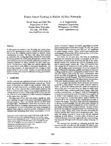
500 802.11 (N=1) Scheme-1, N=4 Scheme-2, N=4 Scheme-3, N=4 Scheme-4, N=4 Scheme-4, N=8
450 400 350 Throughput(KByte/sec)
mensions 1575m × 1575m. The parameters used for the simulation are given in Table 1. We use a Poisson model for packet generation at the MAC layer, where the destination for each generated packet is chosen at random from one of the neighbors1 of the source node.
5
300 250 200 150 100 50 0 0
100
200
300
400 500 Offered Load(KByte/sec)
600
700
800
900
Fig. 3. Throughput performance with schemes using directional transmission of control packets.
A. Effect of directional transmission of control packets Assuming that data packets are always exchanged using directional antennas, we first evaluate the effect of making control packet transmissions directional. We study the following schemes that differ in the way the RTS and CTS packets are sent: • Scheme-1 is used for providing a frame of reference, which uses omnidirectional RTS as well as CTS packets. Only the DATA packets are transmitted and received in the sectorized antennas facing the receiver and transmitter, respectively (see details in [11]). With N = 1 (omnidirectional antennas), this scheme is identical to the IEEE 802.11 MAC. • Scheme-2 uses omnidirectional CTS packets, but the RTS packets are sent only on those sectors that are free from OTA wait periods at the time the data packet is generated. If this restricted omnidirectional RTS transmission is not successful in 7 retries, then the source assumes that the destination is in one of the sectors which is not clear for transmission due to an OTA wait period in effect. In that case, the source waits till all the sectors are clear for transmission, and then sends the RTS in all sectors. • Scheme-3 uses the same scheme for transmitting RTS packets as in Scheme-2, but the CTS packets are sent in only the sector in which the destination receives the RTS. • Scheme-4 uses AOA tables at each node in which it maintains records of the AOA for each node from which it successfully receives a packet. When a data packet is to be transmitted, the source first sends a directional RTS packet on the sector corresponding to the entry for the destination in its AOA table, if such an entry exists. Before sending the directional RTS packet, the source confirms that the chosen sector does not have a OTA wait period in effect. If there is no entry for the destination in its AOA table, then the source proceeds as in scheme-3. If a CTS reply is 1 We
Y.
define node X to be a neighbor of Y if X is within transmission range of
not received, the source tries to send the directional RTS a maximum of 4 times before deciding that the directional RTS has failed. In that event, it waits until all sectors are free and transmits the RTS omnidirectionally. The performances of these schemes are obtained in the RFMACSIM simulator, which has details of wireless path loss, Rayleigh fading characteristics, radio receiver model, and the IEEE 802.11 MAC. The channel and interference models in this MAC simulator adequately captures the factors leading to packet loss in a wireless network. We first consider a static network where the nodes are assumed to be stationary and are placed in a uniform grid. The motivation for using this static scenario is to first derive the minor differences between performance results of the different schemes without regard to random variations caused by mobility. Figure 3 plots the throughput performance of the above schemes using sectorized antennas. For comparison, the throughput performance using the IEEE 802.11 MAC (N=1) for the same network is also plotted. We observe throughput improvements due to all three schemes (schemes 2, 3, and 4) that progressively make transmissions of control packets more directional over the basic scheme for using directional antennas (scheme-1). Directional transmission of RTS and CTS packets effectively increases the capability of the neighbors of nodes that are engaged in data exchange to access the channel. As beamwidths are made narrower, fewer neighbors are silenced by the OTA wait periods, providing more improvements of the throughput. However, the effective gain is not so pronounced when the number of antennas is increased beyond 8. The above MAC protocols using directional antennas provide significant savings in the average power consumption in the transmitters, as observed from Figure 4. The savings in power consumption become more pronounced with increasing directivity and also with more efficient use of the transmissions.
TO APPEAR IN THE PROC. OF IEEE INTER. CONF. ON COMP. COMM. AND NETWORKING (IC3N’02)
180000
20 802.11 (N=1) Scheme-1, N=4 Scheme-2, N=4 Scheme-3, N=4 Scheme-4, N=4 Scheme-4, N=8
160000
802.11 (N=1) Scheme-4,N=4 DMACP,N=4 Scheme-4,N=8 DMACP,N=8
18 16
140000
14 120000 Throughput (Mb/s)
Average power consumed(mw)
6
100000
80000
12 10 8
60000 6 40000
4
20000
2
0
0 0
100
200
300
400 500 600 Offered Load(KByte/sec)
700
800
900
Fig. 4. Average transmission power with schemes using directional transmission of control packets.
0
5
10 15 Offered Load (Mb/s)
20
25
Fig. 5. Throughput performance of scheme-4, DMACP, and 802.11 with omnidirectional antennas. 1.2 802.11 (N=1) Scheme-4,N=4 DMACP,N=4 Scheme-4,N=8 DMACP,N=8
1
Average power consumed (W)
B. Effect of power control We now present the proposed directional antenna based MAC protocol with power control (DMACP): • DMACP protocol: Here, every node maintains an AOA table as described in scheme-4. When the destination receives a directional RTS successfully, it calculates γ, the amount by which the worst case SINR for the duration of the RTS exceeds SIRmin . This is sent over the directional CTS packet to the source. The source node transmits the DATA packet by reducing the transmit power by γ − 6 dB from its normal (maximum) value that uses for control packets. The margin of δ = 6dB is determined by experimentation to be the optimum value that avoids DATA packet loss due to unexpected interference. All other characteristics of the protocol are identical to that of scheme-4. We implement the DMACP protocol in the ns-2 network simulator, which is more flexible for incorporating changes in the contents and usage of control packets. In order to adequately capture the packet loss due to interference, we modified the MAC layer of the version of ns-2 obtained from the CMU Monarch project [2], so that packet loss is now determined from signal-to-interference ratio calculations instead of comparing the received signal power to a threshold [9]. However, these modifications make the code slow and hence we use ns-2 only when necessary, that is to model the final version of our proposed protocol that incorporates the directional transmission of control packets as well as transmitter power control. We use the same network area and the same number of nodes as before, but the MAC parameters used in ns-2 are slightly different. Here transmit power is 25 dBm, CS thresh is -78 dBm, and the SIRmin is 10 dB, with all other parameters being the same as before. The throughput and average power consumption using the DMACP protocol with sectorized antennas are shown in figures 5 and 6, respectively. For comparison, results using scheme-4 (DMACP without power control) as well as the IEEE 802.11 MAC with omnidirectional antennas are also plotted for the
0.8
0.6
0.4
0.2
0 0
5
10
15
20
25
Offered Load (Mb/s)
Fig. 6. Power consumption of scheme-4, DMACP, and 802.11 with omnidirectional antennas.
same network. These results were obtained with node movements modeled according to the random waypoint model with an average speed of 5 m/s and zero pause time. Because of some differences between the physical layer models of ns-2 and RFMACSIM, the throughputs obtained are slightly different on the two simulators. However, we observe the same performance trends. Our results show that there is a four fold increase of throughput using the DMACP protocol. Power control does not have a significant impact on the throughput. However, the average power consumption using the DMACP protocol is lower, as shown in Figure 6. To evaluate the maximum possible efficiency of power consumption with power control, we simulated a fictitious ideal situation where the source node is assumed to have perfect and continuous knowledge of the signal and interference levels at the destination. With this knowledge, the source is made to exercise exact power control for the data packet transmission (without using a constant 6dB margin over the estimated SINR information received for the RTS packet). Though it is not prac-
TO APPEAR IN THE PROC. OF IEEE INTER. CONF. ON COMP. COMM. AND NETWORKING (IC3N’02)
in the mobile nodes. A primary objective of this work is to explore power conservation in a mobile ad hoc network by utilizing directional antennas. It is shown that in addition to using directional antennas for data packets, directional transmission of RTS and CTS packets can also be beneficial. Some practical schemes for implementing directional RTS and CTS transmissions and their corresponding performance results are presented. We further explore the issue of power control and propose a new MAC protocol that uses directional antennas with power control (DMACP). Performance evaluations show that efficient usage of directional antennas can provide significant savings of the transmitter power and also improve the network throughput.
0.9 802.11 (N=1) Scheme-4,N=4 DMACP,N=4 Scheme-4,N=8 DMACP,N=8
0.8
0.7 Packet Delivery Fraction
7
0.6
0.5
0.4
0.3
0.2 5
10
15
20
25
30
Max. Speed (m/s)
Fig. 7. Variation of packet delivery fraction with mobility.
tical for the source to have this knowledge, this study was performed to evaluate the best case power control results. The average power consumption at an offered load of 22 Mb/s for the DMACP protocol, scheme-4 (DMACP without power control), the 802.11 MAC (N=1), and those using ideal power control for N = 1, 4 and 8 are shown in Table 2. The results show that ideal power control with omnidirectional antennas reduce the power consumption by nearly 50%. With 90 0 sectorized antennas (N = 4) ideal power control can save more than 80% power in comparison to the IEEE 802.11 MAC with omnidirectional antennas. DMACP with N = 4 reduces the average power consumption by 70%. When 45 0 sectorized antennas are used (N=8), the power savings using DMACP is about 88%, which can be as high as 91% with ideal power control. These results are relatively same for the two mobile speeds. TABLE II AVERAGE POWER CONSUMPTION USING MAC PROTOCOLS
Protocol IEEE 802.11 (N=1) Ideal case (N=1) Scheme-4, N=4 DMACP, N=4 Ideal case, N=4 Scheme-4, N=8 DMACP, N=8 Ideal case, N=8
Power consumption mW/Mbps Max speed=10 m/s Max speed=30 m/s 200.74 207.24 102.00 111.84 74.78 69.98 68.38 67.92 37.54 32.62 29.30 29.40 25.10 25.25 17.59 17.76
The effect of mobility on the performance of DMACP is shown in Figure 7. As expected, the packet delivery ratio decreases with increasing mobility with the DMACP protocol. The relative effect on the IEEE 802.11 protocol is less pronounced. VI. C ONCLUSION We explored some schemes for medium access control in ad hoc networks to take advantage of using directional antennas
VII. ACKNOWLEDGMENT This work is based in part on research funded by the NSF under grant No. ANI-0096264. R EFERENCES [1] S. Agarwal, S. V. Krishnamurthy, R. H. Katz, and S. K. Dao, “Distributed power control in ad hoc wireless networks”, Proc. of PIMRC’01, 2001. [2] J. Broch, D. A. Maltz, D. B. Johnson, Y-C. Hu, and J. Jetcheva, “A performance comparison of multi-hop wireless ad hoc network routing protocols”, Proc. of 4th Intl. Conf. on Mobile Comp. and Networking (ACM MOBICOM’98), October 1998. [3] Romit Roy Choudhury, Xue Yang, Ram Ramanathan, and Nitin H. Vaidya, “Using directional antennas for medium access control in ad hoc networks”, Technical report, University of Illinois at Urbana-Champaign, March 2002. [4] IEEE Standards Department. Wireless LAN medium access control (MAC) and physical layer (PHY) specifications, IEEE standard 802.11– 1997, 1997. [5] P. Karn. “MACA: A new channel access method for packet radio”, Proc. of ARRL/CRRL Amateur Radio 9th Computer Networking Conf., 1990. [6] Y. B. Ko, V. Shankarkumar, and N. H. Vaidya, “Medium access control protocols using directional antennas in ad hoc networks”, Proc. of IEEE INFOCOM’2000, Mar. 2000. [7] Kou Kobayashi and Masao Nakagawa, “Spatially divided channel scheme using sectored antennas for CSMA/CA - directional CSMA/CA”, Proc. of PIMRC’2000, 2000. [8] T. J. Kwon and M. Gerla, “Clustering with power control”, Proc. of IEEE MILCOM’99, pages 1424–1428, Nov. 1999. [9] K. Li and A. Nasipuri, “Modeling mac perofrmance in mobile ad hoc networks simulations”, Proc. of Comm. Networks and Dist. Syst. Modeling and Simulations, Jan. 2002. [10] J. P. Monks, V. Varghavan, and W. W. Hwu, “A power controlled multiple access protocol for wireless packet networks”, Proc. of INFOCOM’01, 2001. [11] A. Nasipuri, S. Ye, J. You, and R. E. Hiromoto, “A MAC protocol for mobile ad hoc networks using directional antennas”, Proc. of IEEE Wireless Communications and Networking Conference (WCNC 2000), Sept 2000. [12] Charles Perkins and Elizabeth Royer, “Ad hoc on-demand distance vector routing”, Proc. of the 2nd IEEE Workshop on Mobile Computing Systems and Applications, pages 90–100, Feb 1999. [13] R. Ramanathan and R. Rosales-Hain, “Topology control of multihop wireless networks using transmit power adjustment”, Proc. of IEEE INFOCOM’00, pages 404–413, March 2000. [14] Ram Ramanathan, “On the performance of ad hoc networks with beamforming antennas”, Proc. of MobiHoc’2001, pages 95–105, October 2001. [15] T. S. Rappaport, Wireless Communications: Principles and Practice, Prentice Hall PTR, 1999. [16] Mineo Takai, Jay Martin, Rajiv Bagrodia, and Aifeng Ren, “Directional virtual carrier sensing for directional antennas in mobile ad hoc networks”, Proc. of the ACM/SIGMOBILE MobiHoc’2002, June 2002. [17] J. Zander, “Slotted ALOHA multihop packet radio networks with directional antennas”, Electronics Letters, 26(25), 1990.