Power Factor Calculation by the Finite Element Method - IEEE Xplore
Recommend Documents
Even though the analytical software remains the most used tool, the FEA is widely used to ... The use of analytical tools is important to reduce the calcula-.
Power Factor Calculation by The Finite Element Method. Francis Bidaud, R&D
Electrical Motors, TECUMSEH Europe, France. Analytical methodology remains ...
Extension of the Concept of Windings in Magnetic FieldâElectric Circuit ... Index TermsâCoupling, electric circuit, finite element method, magnetic field, ...
Gerrit Mur. IRCTR, Faculty of Informationtechnology and Systems, Delft University of Technology. Ioan E. Lager. Laboratory of Electromagnetic Research, ...
Abstract-- Defects such as cracks and voids in the insulation medium of a power transformer may affect the dielectric response of transformer insulation system.
In particular the first volume which was entitled The Finite Element Method: The ...... alized to give information on the rate of convergence which can be expected ..... large extent of the region introduced in the analysis and the grading of the ...
Feb 10, 2012 - particular rotor geometry of the IPM synchronous motor and the presence of several variables and constraints make the design problem very ...
Invited Review Paper. Abstractâ In this paper, various time-domain finite-element .... method, the trial and test spaces are not necessarily the same. One special ...
tions in an electric machine may cause undesirable 'ripple' forces leading to acoustic noise. It is therefore important that the ripple fields and forces be computed ...
stalled and operational, is the centered activity in the process of assessing the efficacy of distribution ... as a current-limiting reactor. The standard ... of economy interchange and operating benefits versus tie-line capacities as well as versus
Abstract: An enhancement of the finite element method with Kriging shape functions (K-FEM) was recently ... stress resultants in solid and structural mechanics.
9 The patch test, reduced integration, and non-conforming elements ... Generalized patch test (test C) and the single-element test ...... (Horace Walpole, 1754).
Jun 11, 2014 - Once more e can be turned into an immer product on a ... Vu e H, -p(u, v) = | fu ..... Babuška, Ivo; Banerjee, Uday; Osborn, John E. (June 2004).
Dec 2, 2011 - Nouveaux essais sur l'entendement humain (1704/1764). In this section, we ..... found in the literature, see for example [121, 71]. As a concrete ...
Application of the patch test to plane elasticity elements with. 'standard' and 'reduced' quadrature. 337 ...... volume AFFDL-TR-68-150, Wright Patterson Air Force Base, Ohio, Oct. 1968. 7. R.L. Taylor. ...... A.M. Winslow. Numerical solution of the
Dec 2, 2011 - Email: [email protected] ... automatically generating and compiling efficient low-level code, it is possible to parametrize a finite element ... To automate the finite element method, we need to build a machine that takes as input a.
Interdigital transducer. (IDT). Piezoelectric substrate. Acoustic absorber. Figure 1: Sketch of a SAW filter with two Interdigital Transducers (IDTs) they can be used ...
Feb 10, 2016 - Metallic tanks are widely used for the transportation of dangerous goods. Their design and construction fall into the European standard ...
16.810 (16.682). Engineering Design and Rapid Prototyping. Instructor(s). Finite
Element Method. January 12, 2004. Prof. Olivier de Weck. Dr. Il Yong Kim.
(Reeh et al., 1989). Some of the fractures affecting post restorations could be related to concentration of forces. (Sorrentino et al., 2007). In recent years, various ...
Jan 12, 2004 - FEM fundamental concepts, analysis procedure. â«. Errors .... Most commercial FEM software packages originated in the 1970s. (Abaqus, Adina ...
21 May 2003 ... Lecture Notes: Introduction to the Finite Element Method. Lecture Notes:
Introduction to the. Finite Element Method. Yijun Liu · CAE Research ...
Numerical Methods of solving engineering problems. Boeing has started to use FEM. Applications of FEM: I ) Steady state problems(Equilibrium Problems):.
Open access under CC BY-NC-ND license. Open access under CC BY-NC-ND .... For model sphere - flat surface (Fig. 3.b):. -. T = 5mm. -. Pumber of nodes : ...
Power Factor Calculation by the Finite Element Method - IEEE Xplore
3002. IEEE TRANSACTIONS ON MAGNETICS, VOL. 46, NO. 8, AUGUST 2010. Power Factor Calculation by the Finite Element Method. Claudia A. da Silva. 1.
3002
IEEE TRANSACTIONS ON MAGNETICS, VOL. 46, NO. 8, AUGUST 2010
Power Factor Calculation by the Finite Element Method Claudia A. da Silva1 , Francis Bidaud2 , Philippe Herbet2 , and José R. Cardoso3 P&D—Department Tecumseh do Brasil-Planta I, R&D Electrical Motors, São Carlos, São Paulo, CEP 13570-820, Brazil Tecumseh Europe, R&D Electrical Motors, Barentin 76360, France Diretoria Escola Politécnica USP, São Paulo University, LMAG-PEA, São Paulo, SP, CEP 05508-900, Brazil The use of finite element analysis (FEA) to design electrical motors has increased significantly in the past few years due the increasingly better performance of modern computers. Even though the analytical software remains the most used tool, the FEA is widely used to refine the analysis and gives the final design to be prototyped. The power factor, a standard data of motor manufactures data sheet is important because it shows how much reactive power is consumed by the motor. This data becomes important when the motor is connected to network. However, the calculation of power factor is not an easy task. Due to the saturation phenomena the input motor current has a high level of harmonics that cannot be neglected. In this work the FEA is used to evaluate a proposed (not limitative) methodology to estimate the power factor or displacement factor of a small single-phase induction motor. Results of simulations and test are compared. Index Terms—Finite element method, power factor, saturation, single-phase induction motor.
I. INTRODUCTION
T
HE analytical methodology remains as the most important daily work tool of motor designers in the industry. The use of analytical tools is important to reduce the calculation time especially during optimization [1], [5]. However some important phenomena are not every time evaluated particularly when ECM (equivalent circuit models) is involved. Then numerical methods are used with the best results. The use of finite element analysis is very important because it provides detailed simulation and it is more accurate regarding saturation and field distribution. Moreover, even FEA requests more solving time compared to ECM the performance of modern computers increased significantly so, FEA could become the best bet to solve problems where these phenomena need to be taken into account. The literature is full of valuable works that uses the finite element analysis to evaluate the performance of electrical motors as in [2]–[4]. Some works use software developed at academy and others use the commercially available software. Commonly, the power factor is used worldwide to quantify and to tax the real and reactive power of electrical systems. Its definition needs to be reconsidered for systems having non-sinusoidal currents or voltage waveform. The deviations from ideal conditions can lead to mistakes in measurement and taxing. Traditionally, systems that consume alternative power, conand reactive power , fed by sume both the real power the network, if pure sine waves are involved (voltage and currents). The vector sum of real and reactive power is the apparent . The power factor PF of an electric motor is defined power as the ratio of its real power in Watts to the apparent power in VA. The presence of reactive power causes the real power (or useful power) to be less than apparent power, consequently induction motors have power factor less than 1. Motors with low power factor are undesirable load in the network. The power Manuscript received December 21, 2009; accepted February 12, 2010. Current version published July 21, 2010. Corresponding author: C. A. da Silva (e-mail: [email protected]). Color versions of one or more of the figures in this paper are available online at http://ieeexplore.ieee.org. Digital Object Identifier 10.1109/TMAG.2010.2044146
factor of a single-phase induction motor can be easily obtained by tests [6] and confirmed by simulations using the finite element method. But the level of saturation can distort the current curve and leads to false values of power factor if the prior definition is taken. In this work the finite element method is used to evaluate the performance of a small industrial capacitor run, single-phase induction motor. A method to extract the input power of a motor calculated from post-treatment of a finite element model, including consideration of saturation and harmonics, is proposed hereafter. A new factor, displacement factor, is then deducted and calculated. Results of simulations are compared to experimental ones. This work intends to be pedagogic and gives enough information to engineers that are not used to calculation of power factor by the finite element method. II. POWER FACTOR DEFINITION When voltages and currents are pure single sine waveforms power factor PF is defined as the rate of the real power and the apparent power consumed by equipments or devices. The signals varying in time may to be periodicals and of same frequency. The product of signals gives the instantaneous value of power. The average value of this product is the real power . Taking and as the instantaneous value of input voltage and and their rms values, current varying in time and the power factor is obtained with
(1) and If the input voltage is defined as the active power the input current as is obtained with (2). Voltage and current have only the funda. and mental component of frequency and are the peak values of voltage and current. The angle is the phase angle difference between the current and voltage waveform as shown in Fig. 1.
DA SILVA et al.: POWER FACTOR CALCULATION BY THE FINITE ELEMENT METHOD
Fig. 1. Phase angle between current and voltage having the same frequency.
If we take and additionally we have (3) It is possible to show that: (4)
3003
Fig. 2. Different between current charged of harmonics and pure sine wave voltage.
magnetic saturation and so forth. In this case the definition of power factor, as established above, is not correct. Fig. 2 shows the waveform of a sinusoidal input voltage and a saturated input current. It is possible to see that the angle of passage by zero and the one where we have the wave peaks is not the same. Here the definition of power factor, as established for sinusoidal inputs, is lost. Then a new definition needs to be established. First it is necessary to show that the product of voltage versus harmonics current is null for all harmonics (only the product of components having the same frequency has an average value that is not null). For example, if the applied voltage is sinusoidal and the current is limited to a frequency of order 3, the (2) can be rewritten as
(5) (8) Then, with (4) and (5) in (3) we have (6)
If now we take and
we have
Consequently, it is possible to express the active power with (7) As and , replacing (7) in (1) . This is the most academic and traditional we have model used to analyze the power factor and it is called general form. However this definition is true only for cases where the voltage and current are sinusoidal because the angle is always the same no matter whether the passage by zero or the wave peaks is taken by the observer. Motor designers sometimes use the direct model to estimate the power factor. In this model the time of passage by zero is taken directly from curves obtained in simulations. This model may be avoided when waveforms are charged of harmonics, because the notion of constant phase angle difference is lost. We could see for instance actual time differences where the curves change the direction and wave peak occurs. That would lead to calculated values far from the experimental ones. In a non-ideal case, voltage and current may have a non-sinusoidal waveform due to the use of inverters, converters, reactors,
(9) It is possible to show that (10)
(11) , that means, in With (10) and (11) in (9) we have case of voltage and current do not having the same frequency no active power is available. If the input current has a fundamental and a third harmonic, , then the active power is defined as
(12)
3004
IEEE TRANSACTIONS ON MAGNETICS, VOL. 46, NO. 8, AUGUST 2010
TABLE I
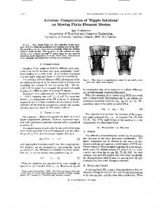
Fig. 3. Design of analyzed single-phase motor.
Fig. 4. Coupled electric circuit of finite element analysis.
III. POWER FACTOR ANALYSIS
As the product of different frequencies will be null, the active power will be defined as (13). Only the fundamental of current carries the active power [7]. (13) Equation (13) states that to obtain the active power it is necessary to extract the fundamental of input current and its regarding the input voltage. displacement When voltage and current have only the fundamental freand has the same meaning and are called quency, power factor. However, when the current has several harmonics has a different meaning and it is called displacement factor. General relations are summarized in Table I. In the next section, results of simulation and test illustrates the theory herein presented.
To analyze the problem of calculation of power factor by the finite element method the single-phase run capacitor motor of 100 W, 60 Hz, 2 poles of Fig. 3 is used. The coupled electric and circuit used in simulations is shown in Fig. 4 where are the main and auxiliary end-winding’s inductances and the run capacitor. The main and auxiliary windings are input to the finite element software and take into account the winding resistances. The basic theory of single-phase induction motor shows that, of input real power of a run capacitor the mean value single-phase induction motor can be obtained by (14) and are the applied voltage, the current where of main winding and the current of auxiliary winding, taken in one period of the time, respectively. The calculation time corresponds to one cycle (1/f) of input power where is the frequency of applied voltage. It is known that the input power of single-phase induction motors has several harmonics and they are more evident in saturated motors where the input current is distorted. The harmonics in the total current, leads to a necessary attention for extraction . of The use of harmonic analysis to calculate the power factor and the displacement factor is not usual in the literature. However,
DA SILVA et al.: POWER FACTOR CALCULATION BY THE FINITE ELEMENT METHOD
3005
TABLE II DISPLACEMENT FACTOR—SPECTRAL ANALYSIS SIMULATION
TABLE III DISPLACEMENT FACTOR—SPECTRAL ANALYSIS TEST
Fig. 5. Curves of I obtained by simulation and test (Steady state).
IV. CONCLUSION This work presented the standard methodologies used to calculate the power factor of electrical motors and an extended model considering the harmonics effects. Finite element approach makes it possible to match the theory. Simulation results and test show that the use of harmonics’ model provides good results for saturated motors. ACKNOWLEDGMENT Fig. 6. Harmonic spectrum of I current.
this methodology is a powerful way to have an accurate result in cases where the motor is saturated for instance. In this work the applied voltage is sinusoidal then the (13) will be used to evaluate the displacement factor. In Fig. 5 we have the experimental and calculated curves of total motor current, . The harmonic spectrum of these currents is presented in Fig. 6. The analysis uses the FFT algorithm that relies on a sample of current taken over the period at steady state. To calculate the displacement factor by use of spectral analysis the continuous component of input power and the rms value of first harmonic of input current are taken from calculation and test. from In the aim to extract the mean input watts value simulations, the and versus time are exported from the post-processor module of software. The mean value is obtained directly with . Tables II and III present the values taken from simulation and test to calculate the displacement factor. The time step of calculation is 0.09 ms and the acquisition time is 0.1 ms. Results obtained by use of spectral analysis are relatively close to the experimental ones.
The authors would like to thank R. Kropfel and H. Queiros for their support during the planning and execution of the experimental work, as well as in the analysis of the results. REFERENCES [1] A. A. Jimoh and D. V. Nicolae, “A study of improving the power factor of a three-phase induction motor using a static switched capacitor,” in Proc. Power Electronics and Motion Control Conf., Aug.–Sep. 2006, pp. 1088–1093. [2] A. H. Isfahani, B. M. Ebrahimi, and H. Lesani, “Design optimization of a low-speed single-sided linear induction motor for improved efficiency and power factor,” IEEE Trans. Magn., vol. 44, no. 2, pp. 266–272, Feb. 2002. [3] C. A. da Silva, N. Sadowski, R. Carlson, N. Lajoie-Mazenc, and Y. Lefevre, “Analysis of the effect of inter-bar currents on the performance of polyphase induction motors,” IEEE Trans. Ind. Applicat., vol. 39, no. 6, pp. 1674–1680, 2003. [4] L. Xu and W. N. Fu, “Evaluation of 3rd harmonic component effects in 5-phase synchronous reluctance motor drive using time stepping finite element method,” in Industry Applications Conf., IAS2000, Conf. Rec., 2000, vol. 1, pp. 531–538. [5] M. Popescu, T. J. E. Miller, M. McGilp, F. J. H. Kalluf, C. A. da Silva, and L. V. Dokonal, “Effect of winding harmonics on the asynchronous torque of a single-phase line start permanent magnet motor,” IEEE Trans. Ind. Applicat., vol. 42, pp. 1014–1023, 2006. [6] Test Procedure for Single-Phase Induction Motors, IEEE Standards, IEEE Std. 114-2001, pp. 23. [7] C.E.M et Electronnique de Puissance University of Nantes, France, p. 94, ch. 3 in collection “Sciences and Technologies,” Prof. J. L. Cocquerelle, IRESTE.