POWER INTERFACES AND STORAGE SELECTION FOR AN ULTRAFAST EV CHARGING STATION H. Hõimoja, M. Vasiladiotis, A. Rufer Swiss Federal Institute of Technology Lausanne, Switzerland, EPFL-LEI, Station 11, 1015 Lausanne,
[email protected]
Keywords: Electric Vehicle, Energy Management, Energy Storage, Cascaded H-bridge.
Abstract
off between autonomy flowrate and autonomy itself is inevitable. However, bearing in mind that an average driver rarely drives hundreds of kilometres non-stop, the autonomy could be de-ranked if ultrafast charging infrastructure coverage is sufficient to provide energy if necessary, not only if available as today [2].
The paper is a summary of the research conducted so far on the ultrafast charging issues of electric vehicles with the main emphasis on the infrastructure. In order to estimate the load curve and peaks resulting from high charging rate, simulations are carried out initially to determine energy and power ratings. Energy storage options for filtering out the perspective peaks are discussed with applicable power interfaces between the grid, the vehicle and the storage buffer. Finally, an ultrafast charging architecture based on cascaded H-bridge converters is proposed.
Table 1: Autonomy and autonomy flowrate comparisons
1 Introduction
2 Energy and power requirements
The electric vehicles (EV) are being continuously promoted by the manufacturers and the governments willing to excel in their environmental awareness. Unfortunately, their good will is in reality limited by existing possibilities concerning the autonomy and charging availability of such cars. The commercialised EVs have datasheet autonomy around 160 km with charging times from 6 h…8 h in domestic conditions down to 20 min if state-of-the-art public quick chargers are employed [1]. The actual problem may be formulated by two distinctive EV-related terms of autonomy and autonomy flowrate:
To determine the design parameters for an ultrafast EV charging station (UFCS), several data must be known or predefined:
1.
2.
Autonomy is the average distance an EV is able to cover with the maximally recharged battery in given conditions (capacity, charging current, initial state of charge etc.). Autonomy flowrate is the driving distance augmentation in time, expressed in km/min or km/h.
These two values determine the quantity and duration of intermediate recharges during a trip and as follows, the total travel time and average speed. For explaining the actual situation, a fuel-efficient diesel family car and a generic EV are compared in Table 1. Whereas the fuel tank capacity is independent of the tanking speed, the available capacity of an electrochemical battery is de-rated at high charging rates, additional influence posed by the ambient temperature. The tanking speed (resp. charging power) is directly related to autonomy flowrate; on the other side, the autonomy of an EV decreases while increasing the charging power. Thus a trade-
Parameter Consumption Tank capacity Autonomy Tanking speed Autonomy flowrate
1) 2) 3) 4) 5)
Diesel car 5 l / 100 km 45 l 900 km 35 l/min 700 km/min
Electric vehicle 15 kW•h / 100 km 24 kW•h 120 km 50 kW 4 km/min
objective charging time; useful battery capacity at objective charging time; initial state of charge (SoC) at the start of charging; efficiencies of energy conversion stages; UFCS utilisation.
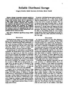
2.1 Battery charging process During charging, the system charger-battery draws not only useful power from the grid, which is accumulated as traction energy for later use, but also additional components to compensate the losses inside the battery Ploss,b and the charging converter Ploss,conv (Fig. 1) As the battery has resistive characteristics caused by the sum of internal and contact resistances of individual cells ∑Rcell, its losses augment with charging current ich squared. The power Pg posed by recharging battery to the grid can be expressed as
Pg =
1
ηconv
⋅ ich ⋅ uoc ( SoC ) + ich ⋅
∑R
cell
(1)
The open circuit voltage uoc of a battery can be considered analogous to counter-emf, increasing with SoC in a non-linear manner. With nearly constant charger converter efficiency ηconv, the grid power must be increased during recharging to keep the constant charging current.
23 h
21 h
0% 19 h
0% 17 h
20% 15 h
2% 13 h
40%
11 h
4%
09 h
60%
07 h
6%
05 h
80%
03 h
8%
Cumulative distribution
100%
01 h
Hourly distribution
10%
Fig. 1: Energy flow from grid to battery Hourly distribution
2.2 Considerations on utilisation
Fig. 4: Typical traffic density distribution in Switzerland
While forecasting the load profile of an UFCS, several assumptions have been made: EV rated battery capacities vary from one vehicle model to another. Moreover, the capacity is prone to ageing and temperature; therefore in simulations the capacities are subjected to left-truncated normal distribution, as shown in Fig. 2. 12%
100%
10%
80%
Percentage
8%
60%
6% 40%
4% 2%
20%
0%
0%
14 18 22 26 30 34 38 42 46 50 54
Cumulative percentage
1.
Ebat [kW·h]
Fig. 2: EV battery capacity Ebat histogram The vehicles arriving at an UFCS have varying initial state of charge, representing the remaining energy inside the battery. The values are subjected to normal distribution as shown in Fig. 3. 100% 80% 60% 40% 20%
Cumulative percentage
8% 7% 6% 5% 4% 3% 2% 1% 0% 50%
46%
42%
38%
34%
30%
26%
22%
18%
14%
6%
10%
0% 2%
Percentage
2.
Cumulative distribution
SoCi
Fig. 3: EV battery initial state of charge SoCi histogram At the given number of vehicles being charged during 24 h, their arrival intervals at an UFCS are uneven, depending on the traffic density in the given hour (Fig. 4).
2.3 UFCS load curve generation procedure The presumed load curve is deducted from the objective number of EV to be charged during a day. For next, following steps are performed: 1. 2.
3. 4. 5.
Hourly distribution of vehicles according to Fig. 4. Assignment of arrival times within the specified hour. A vehicle can arrive at any minute of the given hour, so the minute value is generated randomly. Assignment of the initial state-of-charge SoCi and rated capacity Ebat to each EV. Generating charging curve for each EV based on the objective charging time tch. Superimposing charging curves to achieve sum values.
The EV battery rated voltage UEV,n = 330 V has been considered independent of the vehicle, this value being characteristic to small EVs such as C-Zero, iMiEV and iOn. The SoC for the effective energy exchange range of an EV battery is taken between 100 %...0 % and the resistance is considered reciprocal to its capacity. The base value ΣRcell(16 kW·h) = 70.4 m is taken from a datasheet [3].
ΣRcell ( Ebat ) = ΣRcell (16 kW·h) ⋅
16 kW·h Ebat
(2)
The charging current ich is determined by the battery capacity and objective charging time tch and the open circuit voltage uoc is considered to have linear relationship to SoC with U0 = 0.8·Ubat,N
uoc ( SoC ) = ( 0.8 + 0.2 ⋅ SoC ) ⋅ u EV , n
(3)
The SoC estimation itself is based on the coulomb count: t
∑
∆t SoC (t ) = SoCi + ⋅ ich ,τ , Qbat τ = 0
(4)
where Qbat = Ebat / UEV,n is the so-called coulomb capacity of a battery and t numeric integration timestep. The charging process is terminated when SoC ≈ SoCmax. The battery terminal voltage is a sum of uoc and the voltage drop across the internal resistance:
uEV (t ) = uoc ( SoC ) + ich ⋅ ΣRcell
(5)
The charging power PEV is defined as:
3.1 Scheduling with power limitation
2.4 Simulation results The probabilistic load curve simulations were carried out for UFCS utilisation scenarios of 50 EV/day, 100 EV/day and 200 EV/day with input data distribution as explained in Fig. 2 to Fig. 4. The objective charging time was taken tch = 5 min from SoC(t) = SoCi … 100 % for each EV. The charger efficiency was taken ηconv = 95 %. For each utilisation scenario, 10’000 Monte Carlo iterations were made based on other authors’ experience [4] [5]. The simulated charging power values are shown in Table 2, where the median value represents the lower 50 % of all the iterations and the 3rd quartile the lower 75 %, respectively as known from the descriptive statistics theory. Station max [kW] 1’421 1’733 2’218
Per single EV [kW] Median: 214 rd 3 quartile: 284 Max: 697
Table 2: Power ratings of an UFCS for tch = 5 min The energies transferred from the utility grid to the vehicles during a day are shown in Table 3. EV/day 50 100 200
Median 907 kW·h 1’851 kW·h 3’652 kW·h
3rd quartile 942 kW·h 1’901 kW·h 3’729 kW·h
Max 1’113 kW·h 2’220 kW·h 4’061 kW·h
For economic reasons, the design of an UFCS should be based rather on optimal than on worst-case values. As for charging power limitation, the 3rd quartile values permit to recharge an EV within 5 minutes at 75 % of all cases (Table 2, Pch = 284 kW). The same can be said about the number of charging ports per UFCS. However, with limited charging power and EV connection ports, waiting queues emerge (Table 4) [6]. A sample load diagram with scheduling and charging power limitation is depicted in Fig. 6. EV/ day 50 100 200
N° of EV ports Simulations’ max 4 6 8
Proposed 1 2 3
Waiting time [min] 3rd quartile Max 5.6 21.9 2.5 11.3 1.0 10.4
Table 4: Queues at charging power limited to 3rd quartile 900 kW 800 kW 700 kW 600 kW 500 kW 400 kW 300 kW 200 kW 100 kW 0 kW 00.00 h 01.30 h 03.00 h 04.30 h 06.00 h 07.30 h 09.00 h 10.30 h 12.00 h 13.30 h 15.00 h 16.30 h 18.00 h 19.30 h 21.00 h 22.30 h
(6)
PEV (t ) = uEV (t ) ⋅ ich
EV/day 50 100 200
3 Load management and buffering
Table 3: Energy ratings for and UFCS for tch = 5 min
Fig. 6: A sample scheduled load curve for 200 EV/day
If the vehicles arrive at an UFCS with an interval shorter than charging time, the grid burden is summed up of individual charging curves (Fig. 5). In implementation, to enable simultaneous charging of multiple vehicles, corresponding number of EV interfaces, i.e. charging ports must be foreseen.
With the power limitation related scheduling, the maximum grid burden of an UFCS can be reduced to a fixed value, defined by the number of EV ports and charging power allocated to each port. 3.2 The concept of buffering
00.00 h 01.36 h 03.12 h 04.48 h 06.24 h 08.00 h 09.36 h 11.12 h 12.48 h 14.24 h 16.00 h 17.36 h 19.12 h 20.48 h 22.24 h
1800 kW 1600 kW 1400 kW 1200 kW 1000 kW 800 kW 600 kW 400 kW 200 kW 0 kW
Fig. 5: A sample unmanaged grid load curve for 200 EV/day
Even with scheduling, the UFCS load on a utility grid has a highly fluctuating character. Such short-time peaks necessitate overdimensioning of the infrastructure, including cables, transformers and switchgear. A possibility of peak mitigation lies in partial decoupling of the load from the grid, which is done by energy storage elements acting as an intermediate buffer between the EV and the utility grid. The same approach has already been applied in fast refilling of compressed air powered vehicles [7]. The major components of a buffered UFCS are (Fig. 7): 1.
Low power charger LPC keeps the SoC to guarantee EV charging power availability and limits the grid load to an average value. It must transmit only charging power for the stationary buffer. During EV charging, it operates in parallel with the intermediate buffer IB.
2.
3.
High power charger HPC charges the EV, drawing energy both from the grid and the buffer. It must transmit the full EV charging power. The intermediate buffer IB, connected to the dc bus between the LPC and HPC, charges with lower power from the grid and discharges into the vehicle(s).
3.3 Example of power levelling The levelling means suppressing load variations seen from the grid side; this is done by setting the objective grid power Pg,obj(t) to follow load moving average value over a predefined period T rather than its instantaneous value:
1 Pg ,obj (t ) ≈ ⋅ T
t
n
∫ ∑P
HPC ,i
⋅ dτ
(11)
t −T i =1
It must be commented, that in Equation (11), the energy is assumed to be stored and converted without losses. In example (Table 5), the averaging period T = 1 h and already scheduled charging power as described in Table 4. EV/ day 50 100 200
Buffered power [kW] 284 568 852
Buffered energy [kW·h] 144 218 334
Grid connection [kW] 112 196 426
Table 5: Values for a buffered UFCS with levelling strategy For an example of 200 EV/day, the grid connection can be downscaled approximately 5 times in comparison with unmanaged supply (Table 2) and 2 times as compared with non-buffered scheduling (Table 4). A graphical representation of levelled grid load curve is shown in Fig. 8 (to be compared with Fig. 6). 500 kW 400 kW
The buffered UFCS design must take into account the system’s overall energy balance over specified time: t1
n t1
t1
∫ P (t ) ⋅ dt = ∑ ∫ P
HPC ,i (t ) ⋅ dt
g
0
∫
+ PIB (t ) ⋅ dt
i =1 0
(7)
0
The cumulative buffered power, i.e. energy is expressed as: t
200 kW 100 kW 0 kW
Fig. 8: A sample levelled grid load curve for 200 EV/day
∫
EIB (t ) = PIB (τ ) ⋅ dτ
(8)
4 Energy storage selection and interfacing
0
The necessary capacity for the intermediate buffer can be expressed as:
EIB = max EIB (t ) − min EIB (t ) 0...24 h
300 kW
00.00 h 01.25 h 02.50 h 04.15 h 05.40 h 07.05 h 08.30 h 09.55 h 11.20 h 12.45 h 14.10 h 15.35 h 17.00 h 18.25 h 19.50 h 21.15 h 22.40 h
Fig. 7: A buffered UFCS with two EV ports
0...24 h
(9)
While the intermediate buffer charging power is limited by the available grid power Pg,max, the discharging power is defined by the difference between the grid and EV charging power. In an ultimate case the EV charging power is provided only by the buffer, like by following the real-time tariff. Thus,
PIB = − nEV ⋅ PLPC
(10)
The minus sign “-“ in Equation (10) means that the buffer acts as a source, while during buffering from the utility grid it acts as a sink.
4.1 Qualifying criteria The first step in selection is to determine the buffer discharge times, expressed as the ratio between EIB and PIB. From Table 5, the discharge times vary from 23 min to 30 min, falling into the grey zone between short- and long-term storages [8]. Secondly, the number of full recharge/discharge cycles helps to determine the prospective lifetime of the installed buffer. The number of daily cycles can be achieved whilst dividing the transferred energy in 24 hours (Table 3) with buffer capacity (Table 5). Finally, the specific energy and specific power values help to determine the resulting mass and volume of the prospective intermediate buffer (Table 6).
Storage medium Lithium ion battery Lead-acid battery Flywheel Ultracapacitor
Mass [t] 3 65 11 55
Volume [m³] 1 17 16 74
Prospective lifetime 1 year 3 months 20 years 20 years
Table 6: Storage media comparison for 200 EV/day The state of art of energy storage does not give a clear answer to the optimal storage medium selection in terms of installation space, lifetime and costs. To improve lifetime, the electrochemical batteries must be overdimensioned to narrow the SoC window. Another possibility lies in the use of the socalled second-life batteries dismantled from the vehicles or other applications and still capable to serve in an UFCS with de-rated capabilities [9]. 4.2 Storage media interfacing In many cases the storage medium is not connected directly to the common power bus between the primary supply and the load, but by means of a power interface either to convert the energy from one form to another or to match the voltages between the storage medium terminals and the power bus. In an intermediate buffer as shown in Fig. 7, the storage medium can be interfaced to the power bus in following ways: 1.
2.
Storage medium Lead-acid Lithium-manganese Lithium-iron-phosphate Lithium-titanate Ultracapacitor
Voltage window (0.85…1.20)·ubat,n (0.73…1.11)·ubat,n (0.88…1.25)·ubat,n (0.67…1.24)·ubat,n (0.5…1.0)·ubat,n
Table 7: Operational voltage windows for storage media
5 Connection to medium voltage utility grid Even with levelling, the UFCS necessitate a strong grid connection. In low voltage (LV) networks, power levels such as in Table 5 require cables with large cross-section and vicinity of a transformer substation. So it might be argued, that any UFCS is connected to a medium voltage (MV) grid over an interface. A conventional method of interfacing an UFCS to MV grid would be that through an isolated low frequency power transformer (Fig. 10) [5]. As the low frequency passive components add weight and volume to the system, alternative solutions based on ac/dc conversion on the MV side should be considered with medium frequency (MF) galvanic isolation.
Direct interfacing (Fig. 9a) is possible when the HPC input voltage uHPC tolerance is sufficiently high to accept the whole storage medium SoC-related terminal voltage ubat window. The energy exchange with storage medium is controlled only by the LPC and HPC. Parallel active interfacing (Fig. 9b) gives an additional energy flow control degree of freedom from and to the storage medium. The HPC input voltage can be kept constant independently of the buffer’s SoC. Fig. 10: Conventional UFCS MV connection The proposed UFCS architecture is based on the cascaded Hbridge converter topology with split integrated storage (CHB+SIS, Fig. 11) [10]. Besides CHB topology and integrated storage, one of the distinctive characteristics of this design is the paralleled high power charger (PHPC).
Fig. 11: CHB-based UFCS Fig. 9: Storage medium interfacing in intermediate buffer An interface in an intermediate buffer adds complexity to the system, so direct connection should be preferred provided the HPC remains operational in whole storage medium voltage window ubat, like explained in Table 7.
A diagram of CHB-based UFCS is shown in Fig. 12. The proposed structure is bidirectional in terms of power flow and can also provide reactive compensation and frequency control. Besides the absence of bulky low frequency power transformer, the CHB design offers lower harmonic distortion, better fault handling and control flexibility.
Fig. 12: Architecture of an UFCS based on the cascaded H-bridge and split integrated storage
6 Conclusions The research activities summarised in current paper allow drawing the following main conclusions: 1.
2.
3.
4.
5.
Ultrafast charging impact on the utility grid grows with the EV market penetration. During peak hours, the charging powers of single EVs sum up. The peaks on the grid side might be alleviated with load scheduling, with the trade-off of waiting queues and longer charging times thanks to power limitation. The load levelling strategy by the application of intermediate buffering helps furthermore to downsize the necessary grid connection. Levelling is more effective at low UFCS utilisation, when the moving average charging power exceeds the charging power of a single EV. There are presently no optimal storage solution in terms of weight, volume, lifetime and cost. A possibility lies in re-using the de-rated “second-life” batteries. A promising UFCS architecture is CHB+SIS based, offering more compactness, fault handling features and control flexibility than power transformer based one.
As the next step, the project team is designing an ultrafast charging demonstrator, capable of recharging a stock EV from the 32 A household socket during 5 minutes.
Acknowledgements The authors would like to thank the Competence Centre Energy and Mobility (CCEM) as well as the Swisselectric Research for their continuous support to the EPFL industrial electronics laboratory research team in the field of EV infrastructure related studies.
References [1] M. Kamachi, H. Miyamoto, Y. Sano. “Development of Power Management System for Electric Vehicle “i-
MiEV"”, in the Proc. of International Power Electronics Conference, pp. 2949-2955 (2010). [2] H.M. Magraner. “Ultra-Fast DC Charging Stations”, ECPE Workshop on Power Electronics for Electric Vehicles, 23 p. (2011). [3] GS Yuasa product review 2011 [Online]. Available: http://www.gsyuasa-lp.com/Products.html [Accessed December 11, 2011]. [4] K. Yunus, H. Zelaya de la Parra, M. Reza. “Distribution Grid Impact of Plug-In Electric Vehicles Charging at Fast Charging Stations Using Stochastic Charging Model” in the Proc. of European Power Electronics Conference, 11 p. (2011). [5] S. Bai., Y. Du., S. Lukic. “Optimum design of an EV/PHEV charging station with DC bus and storage system”, in the Proc. of IEEE Energy Conversion Conference and Exposition, pp. 1178-1184 (2010). [6] H. Hõimoja, A. Rufer. “Infrastructure Issues Regarding the Ultrafast Charging of Electric Vehicles”, International Advanced Mobility Forum, 8 p. (2012). [7] A. Rufer, S. Lemofouet, M. Habisreutinger, M. Heidari, A. Leuba. “Driving and Filling Personal Vehicles – The Questions of Energy - and Power - Density”, in Geneva World Engineers’ Convention, 9 p. (2011). [8] M.A. Guerrero, E. Romero, F. Barrero. “Overview of Medium Scale Energy Storage Systems” in the Proc. of Compatibility and Power Electronics, pp. 93–100 (2009). [9] H. Hõimoja, M. Vasiladiotis, S. Grioni, M. Capezzali, A. Rufer, H. B. Püttgen. “Toward Ultrafast Charging Solutions of Electric Vehicles”, Cigré 2012 Paris session, 8 p. (2012). [10] L. Maharjan, S. Inoue, H. Akagi, J. Asakura. “A transformerless battery energy storage system based on a multilevel cascade PWM converter”, in the Proc. of IEEE Power Electronics Specialists Conference, pp. 4798– 4804 (2008).