Proceedings of the 2004 IEEE International Conference on Control Applications Taipei, Taiwan, September 2-4, 2004
Practical approach to modelling and controlling stick-slip oscillations in oilwell drillstrings Eva María Navarro-López and Rodolfo Suárez
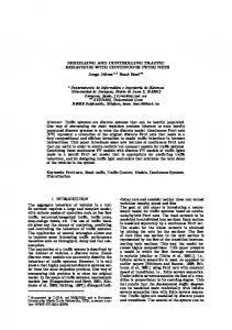
Abstract— Stick-slip friction-induced oscillations appearing in oilwell drillstrings are a source of failures which reduce penetration rates and increase drilling operation costs. For this reason, a major problem to solve is modelling the drillstring torsional behaviour and proposing control solutions to help reduce stick-slip phenomenon. This paper is focused on both problems. On the one hand, it presents dynamic drillstring models in order to reproduce stick-slip vibrations under different operating conditions. The model used for the torque on the bit is the main difference with respect to other models proposed in the literature. On the other hand, some experience-based control estrategies are evaluated in order to reduce stick-slip oscillations. These estrategies will use the angular velocity at the drillstring upper part, the torque on the bit and the weight on the bit, proved to have a key importance in the reduction of drillstring torsional vibrations. The control approach followed is a decentralized one, i.e., the angular velocity at the top end of the drillstring and the bit velocity are controlled separately. The supervisory task is made by the driller.
I. INTRODUCTION Drillstring vibrations are classified depending on the direction they appear. Three main types of vibrations are distinguished: torsional (stick-slip oscillations), axial (bit bouncing phenomenon) and lateral (whirl motion due the out-of-balance of the drillstring). This paper is focused on drillstring stick-slip oscillations. One of the consequences of stick-slip oscillations is that the top of the drillstring rotates with a constant rotary speed, whereas the bit rotary speed varies between zero and up to six times the rotary speed measured at the surface. The mechanism originating this behaviour is now explained. Downhole conditions, such as significant drag, tight hole, and formation characteristics can cause the bit to stall in the formation while the rotary table continues to rotate. When the trapped torsional energy (similar to a wound-up spring) reaches a level that the bit can no longer resist, the bit suddenly comes loose, rotating and whipping at very high speeds. This stick-slip behaviour can generate a torsional wave that travels up the drillstring to the rotary top system. Because of the high inertia of the rotary table, it acts like a fixed end to the drillstring and reflects the torsional wave back down the drillstring to the bit. The bit may stall again, and the torsional wave cycle repeats. This loading is harmful This work has been partially supported by CONACYT grant, ref. 35989A and IMP project D.00222.02.002 E.M. Navarro-López is with the Research Programme on Applied Mathematics and Computer Science (PIMAyC), Instituto Mexicano del Petróleo (IMP), Eje Central Lázaro Cárdenas, 152, ed. 2, planta baja, cub. 1, A.P. 14-805, 07730 Mexico, D.F., Mexico
[email protected] R. Suárez is also with the PIMAyC-IMP
[email protected]
0-7803-8633-7/04/$20.00 ©2004 IEEE
not for its amplitude, but due to its cyclic nature. Indeed, stick-slip appears during the 50% of drilling time [3], [8], [13]. In addition, the whipping and high speed rotations of the bit in the slip phase can generate both severe axial and lateral vibrations at the bottom-hole assembly (BHA). Four main kinds of problems can be originated from these vibrations, such as: (i) drill pipe fatigue problems [13] (causing drillstring connection failures); (ii) drillstring components failures [13], [19]; (iii) wellbore instability [23]; (iv) bit damage [8], [17], [18], [19], [29]. Although the effect of stick-slip vibrations is more significant in bits with polycristalline diamond compact cutters (PDC bits), recent studies have addressed the harmful consequences of torsional, axial and lateral vibrations in roller-cone bits [5]. This paper will be focused on two problems. First, the problem of modelling the drillstring behaviour considering the effect of friction appeared between drillstring components and between the drillstring and the formation. Second, the problem of reducing stick-slip conditions by means of the alignment of different drilling parameters, such as: rotary speed, drilling torque and weight-on-bit (WOB). The approach followed will be of decentralized type and will capture qualitatively driller’s expertise. The models used will be based on lumped parameter differential equationsbased models. The problem of modelling stick-slip motion in a drillstring by means of a lumped-parameter model has been studied from several points of view. Most of them consider the drillstring as a torsional pendulum with different degrees of freedom, for instance: [12], [16], [28] propose singledegree-of-freedom models, [1], [3] propose two-degreeof-freedom models including a linear controller, and [9], [20], [27] present two-degree-of-freedom models for the mechanical part of the system plus the model for the rotary table electric motor system. Manipulating different drilling parameters as increasing the rotary speed, decreasing the weight-on-bit (WOB) or modifying the drilling mud characteristics are shown in the field to suppress stick-slip motion [25]. More effective control methodologies have appeared in the literature in order to compensate drillstring stick-slip vibrations. These methods can be divided into classical control techniques and more sophisticated ones. In the first group, the following ones are highlighted: 1) Introduction of what is regarded as soft torque rotary system (STRS) at the top of the drillstring [7], [25], [26]. A torque feedback is proposed, the underlying idea is making the top rotary system behave in a
1454
“soft” manner rather than as a fixed heavy flywheel. The torsional waves arriving at the surface are then absorbed, breaking the harmful cycling motion. This system has been incorporating in different wells and it has reduced significantly torque fluctuations at the surface (up to 80%) and bit stick-slip conditions [10], [31]. 2) Introduction of a vibration absorber at the top of the drillstring [9] which follows the same approach given in [7], [25]. 3) Introduction of a PID controller at the surface in order to control the rotary speed [21]. 4) Introduction of an additional friction at the bit [21]. A more sophisticated control methodology is used in [27] where a linear H∞ control is used to suppress stick-slip motion at the bit. This work is focused on the drillstring analysis and the goal is to give some operating recommendations in order to maintain optimal drilling conditions. The next step will be the design of a robust controller. The paper is organized as follows. Section II presents a model of the drillstring oriented to described stick-slip oscillations. The bit/rock interaction will be considered as a dry friction leading to a decreasing torque-on-bit with increasing bit angular velocity for low velocities. A PID control action is added to the model at the top end of the drillstring in order to maintain the top velocity constant. The goal of this control action is not suppressing stickslip oscillations. Section III shows an alternative model for the drillstring considering a torque-on-bit in the slipping phase which includes a harmonically-oscillating WOB. This model is proposed in [24] and will be compared with the other model presented in this paper for control purposes. Control solutions to the reduction of stick-slip conditions are given in Section IV. Two alternatives are presented: on the one hand, a bit-velocity varying WOB, on the other hand, the introduction of a damped vibration absorber at the down end of the drillstring. Some notes on the problem of estimating and measuring parameters at the downhole are also given. Conclusions and comments on future works are presented in the last section. II. DYNAMIC MODELLING OF A GENERIC DRILLSTRING The drillstring consists of the BHA and drillpipes screwed end to end to each other to form a long pipe. The BHA comprises the cutting device, regarded as bit, stabilizers (at least two spaced apart) which prevent the drillstring from underbalacing, and a series of pipe sections which are relatively heavy known as drill collars. Drillstrings usually include at the top of the BHA a section of heavy-weight drill pipe. While the length of the BHA remains constant, the total length of the drill pipes increases as the borehole depth does so and can reach several kilometers. An important element in the drilling is the drilling mud or fluid which, among others, has the function of cleaning, cooling and
lubricating the bit. The drillstring is rotated from the surface by an electrical motor. The rotating mechanism can be of two types: a rotary table or a top drive. The shaft of the top electrical motor (DC or AC) is coupled to the drillstring by means of gears, a rotary table and a driving squaredsection pipe called kelly (in the case of the rotary-table drilling system) or by gears (in the case of a top-drive drilling system). This section will present a model for describing this physical system. Two main modelling problems have to be distinguished when studying the drillstring behaviour: the problem of modelling the drilling system and the modelling of the rock-bit interaction, which is usually modelled by frictional forces. The rock-bit interaction is simplified by means of a dry friction model. These two problems are considered in Section II-A. In addition, in Section II-B the model proposed in Section II-A will be combined with a mechanism in order to maintain the top-drillstring rotational speed constant, which is one of the main goals of the driller. Although the model used is a simplification of the drillstring behaviour, it collects the most important phenomena concerning drillstring torsional vibrations. A. Model describing drillstring torsional behaviour The drillstring torsional behaviour is described by a simple torsional pendulum driven by an electric motor and the bit-rock interaction is modelled by a dry friction model. The drill pipes are represented as a linear spring of torsional stiffness k and a torsional damping c which are connected to the inertias Jr and Jb , corresponding to the inertia of the rotary table or the top drive and to the inertia of the pipeline plus the inertia of the downhole end, respectively. Jb is usually considered as the sum of the BHA inertia plus one third of the drill pipes inertia [3]. A dry friction torque plus a viscous damping torque are also considered at the rotary table. See Fig. 1. The model presented is similar to the ones given in [9], [20], [27] with the difference that, here, the dynamics of the top electric motor is not considered and the WOB is included. Some assumptions are made, such as: (i) the borehole and the drillstring are both vertical and straight, (ii) no lateral bit motion is present, (iii) the rotary top system is supposed to have an angular velocity different from zero (iv) the friction in the pipe connections and between the pipes and the borehole are neglected, (v) the drilling mud is simplified by a viscous-type friction element at the bit, (vi) the drilling mud fluids orbital motion is considered to be laminar, i.e., without turbulences. Then, the equations of motion are the following ones: Jr ϕ¨ r + c(ϕ˙ r ¡ ϕ˙ b ) + k(ϕr ¡ ϕb ) = Tm ¡ Tr (ϕ˙ r ) Jb ϕ¨ b ¡ c(ϕ˙ r ¡ ϕ˙ b ) ¡ k(ϕr ¡ ϕb ) = ¡Tb (ϕ˙ b )
(1a) (1b)
with ϕr the angular displacement of the rotary top system, ϕb the angular displacement of the BHA, Tm the drive torque coming from the electrical motor at the surface. Tr , Tb
1455
T fb
Tf b c r 'ç r + T f r
T sb
Tsb
Tcb
Tcb
Transition from stick to slip
2D v
'ç b
à T cb
à T cb à Tsb
Transition from stick to slip
à Tsb
(2)
(1)
c b 'ç b + T f b
'ç b
Fig. 2. Friction at the bit: (1) dry friction with an exponential-decaying law at the sliding phase; (2) switch friction model with a variation of Karnopp’s friction model Fig. 1. Mechanical model describing the torsional behaviour of a generic drillstring
represent the dry friction torque plus the viscous damping torque associated with Jr and Jb , respectively, that is, Tr (ϕ˙ r ) = cr ϕ˙ r + Tcr sgn(ϕ˙ r )
(2a)
Tb (ϕ˙ b ) = cb ϕ˙ b + T fb (ϕ˙ b )
(2b)
where cr and cb are the damping viscous coefficients associated with the rotary top system and the bit, respectively; Tcr is the Coulomb friction torque or sliding torque associated with Jr . The expression for T fb will be a variation of the Stribeck friction together with the static friction (dry friction) model [2]. The dry friction model, i.e., the multi-valued characteristic of T fb when ϕ˙ b = 0, will be approximated by a combination of the switch model proposed in [14], [15] and the dry friction model in which a zero velocity band is introduced (Karnopp’s model [11]). Thus, if |ϕ˙ b | < Dv , |Teb | • Tsb Teb (x) (stick) T sgn(T (x)) if |ϕ˙ b | < Dv , |Teb | > Tsb eb sb T fb (x) = (stick-to-slip transition) ˙ ˙ W µ ( ϕ )sgn( ϕ ) if |ϕ˙ b | ‚ Dv R b ob b b b (slip) (3) with i h µb (ϕ˙ b ) = µcb + (µsb ¡ µcb )e−γb |ϕ˙b | (4) Teb (x) = c(ϕ˙ r ¡ ϕ˙ b ) + k(ϕr ¡ ϕb ) ¡ cb ϕ˙ b
where x = (ϕr , ϕ˙ r , ϕb , ϕ˙ b )T is the system state vector, µb (ϕ˙ b ) is the velocity-depending dry friction coefficient at the bit, µsb , µcb are the static and Coulomb friction coefficients associated with the inertia Jb with 0 < µcb < µsb < 1, γb is a positive constant, Tsb is the static friction torque associated with Jb and Tsb = RbWob µsb , Rb is the bit radius, Wob is the WOB, which is directly related with the hook-on-load applied at the surface, Teb (x) is the applied external torque that must overcome the static friction torque
Tsb to make the bit move, and Dv > 0 especifies a small enough neighbourhood of ϕ˙ b = 0. The resulting friction model is represented in Fig. 2, and it is compared with a classical dry friction model with an exponential-decaying law at the sliding phase. The dry friction torque T fb for ϕ˙ b > 0 varies between Tsb and Tcb = RbWob µcb . Friction torque (3)-(4) leads to a decreasing torque-on-bit Tb with increasing bit angular velocity for low velocities which acts as a negative damping (Stribeck effect, see [2]) and is the cause of stick-slip self-excited vibrations. The exponential decaying behaviour coincides with experimental torque values and is inspired in the models given in [1], [3], [21], [24]. B. Consideration of a mechanism to maintain the top velocity constant In model (1) the top driving motor dynamics is not considered. A starting point for the control design is assuming that arbitrary torques Tm can be applied without taking into account the actuator dynamics generating this torque. Then, it is considered that Tm = u, with u the control input. This control input, in order to satisfy one of the most important driller’s goals, can be proposed in such a way that the top rotary velocity is constant. Control u can be proposed as a proportional-integral-derivative (PID) control action, similar to the model used in [1] where a PD control action is introduced in the system. Then: u(t) = K p (Ωt ¡ ϕr ) + Kd (Ω ¡ vr ) + Ki y
(5)
|u| • umax
(6)
Rt
with Ω the reference velocity, y = t0 (Ωτ ¡ ϕr (τ))dτ, and K p > 0, Kd > 0, Ki > 0, t0 > 0. Control u is supposed to be bounded, therefore, it is saturated to some value umax > 0,
Model (1)-(4) with (5) subjected to (6) describes the drillstring torsional behaviour and the ocurrence of stickslip oscillations depending on some drilling parameters. According to field experience, the increase of Ω and the decrease of the WOB can make stick-slip disappear, see Fig. 3. Note that when stick-slip oscillations appear, important
1456
Time (s)
torque fluctuations appear, as it is reported in real wells [3], [5], [8], [13], [22], see Fig. 3.3. Control action u also presents an oscillatory behaviour when stick-slip oscillations appear in the system. The model parameters used for the simulations are: Jr = 0.518 kg m2 , Jb = 0.0318kg m2 , cr = 0.18 N m s/rad, c = 0.0001 N m s/rad, cb = 0.03 N m s/rad, k = 0.073 N m/rad, Tcb = 5 N m, Tsb = 8 N m, Tcr = 0.5 N m, Dv = 10−6 , γb = 0.9, umax = 20, K p = 3, Kd = 10, Ki = 4. Inertias, stiffness and damping coefficients correspond to a reduced-scale model extracted from [20]. Although these values do not correspond with real parameters, they can be used to describe the behaviour of the drillstring.
III. AN ALTERNATIVE MODEL FOR THE TORQUE ON THE BIT In this section, an alternative model for the torque-on-bit Tb in the slipping phase (when ϕ˙ b > 0) is considered. This model is proposed in [24] for PDC bits and considers the coupling between axial and torsional vibrations. The axial drilltring dynamics is considered through the introduction of the vertical varying force Wob affecting the bit. The torqueon-bit will depend on an harmonically oscillating Wob and, the modification presented in this work is the addition of a viscous friction term in the torque-on-bit. The expression of the torque-on-bit takes the following form: Tb (t, x) = cb ϕ˙ b + T fb (t, x)
Control u, bit torque (Nm)
Time (s)
(3)
(4)
Time (s)
Fig. 3. Some simulations for model (1)-(4) with (5) subjected to (6): (1) – ϕ˙r , − − ϕ˙b with Tb versus ϕ˙b in the small box, with Ω = 17 rad/s, Wob = 1 N; (2) – ϕ˙r , − − ϕ˙b with Ω = 16 rad/s, Wob = 1 N; (3) Tb versus time for stick-slip case with Ω = 16 rad/s, Wob = 1 N; (4)– ϕ˙r , − − ϕ˙b with Ω = 16 rad/s, Wob = 0.1472 N
(7)
U
Time (s)
Velocity (rad/s)
Velocity (rad/s)
Time (s)
Tob/t
Bit torque (Nm)
(4)
(3)
(2)
Control u, bit torque (Nm)
Time (s)
Time (s)
Bit torque (Nm)
Velocity (rad/s)
Bit velocity (rad/s)
(1)
(2) Velocity (rad/s)
Bit torque (Nm)
Velocity (rad/s)
(1)
Time (s)
Time (s)
Fig. 4. Some simulations for model (1) with (7)-(9) with (5) subjected to (6) with Tcr = 0.1 N m, ta = 30, α = 0.1, µ = 1.5, a = 0.03: (1) – ϕ˙r , − − ϕ˙b with Ω = 5 rad/s, Wob0 = 10N; (2) – Tb , − − u with respect to time for the same data as in (1); (3) – ϕ˙r , − − ϕ˙b with Ω = 20 rad/s and the same data as in (1); (4) – Tb , − − u with respect to time for the same data as in (3)
with Teb (x) T sgn(T (x)) eb sb T fb = µb RbWob (t) sgn(ϕ˙ b ) 2
if |ϕ˙ b | < Dv , |Teb | • Tsb (stick) if |ϕ˙ b | < Dv , |Teb | > Tsb (8) (stick-to-slip transition) if |ϕ˙ b | ‚ Dv (slip)
and
Wob (t) = Wob0 (1 + α cos(2πt/ta ))
(9)
with Teb (x) as defined in (4), Wob0 > 0 and 0 < α < 1 constants. The constant µb is the friction coefficient. In [24], Wob0 is considered to depend on the hook-on-load. Model (1) with (7)-(9) and (5) subjected to (6) describes the drillstring torsional behaviour and the ocurrence of stick-slip oscillations. Similarly to model (1)-(4), the model presented in this section captures the fact that an increase of the velocity Ω and a decrease of the WOB make stickslip oscillations disappear. In addition, a phenomenon when ocurring stick-slip oscillations is captured in this model which did not appear with the torque-on-bit defined by (3)-(4). This phenomenon is the association with stickslip oscillations of a backwards movement at the bit when the transition from stick to slip is presented. See Fig. (4). Simulations presented below are obtained with the data used in Section II-B. Drillstring models presented in this section and in Sections II-A and II-B will be used for control purposes in the next section.
1457
(1)
A. Manipulation of the WOB From field data experience and from simulations of the models studied, it is concluded that the manipulation of the Wob can be a solution for stick-slip oscillations even for low velocities Ω. Increasing velocities at the rotary top driving system may lead to lateral vibrations, that is why the manipulation of the WOB can be an alternative solution in order to attenuate stick-slip oscillations. The variation of the WOB is proposed as follows: Wob (ϕ˙ b ) = Kw |ϕ˙ b | +Wob0
(10)
with Wob0 > 0 and Wob ‚ Wob0 . Expression (10) captures two main characteristics of the WOB: (i) as long as ϕ˙ b decreases, Wob decreases; (ii) the WOB must be maintained to a minimal value Wob0 to assure a desirable rate of penetration, too low values of Wob would make drilling stop. Wob0 should not be considered constant and should be analyzed in relation to the depth drilled and the increasingwhile-drilling drillstring length. Wob -variation law (10) can be applied to model (1)(4) with (5) subjected to (6) for a drilling parameters combination for which stick-slip oscillations are presented. This is the case of considering Ω = 16 rad/s and Wob0 = 1 N as it is shown in Fig. 3.2. The results are presented in Figs. 5.1 and 5.2. Similar results are obtained by considering (10) and Tb as defined by (7)-(9). In this case, although stick-slip cycles are suppressed, the oscillating behaviour of ϕ˙ b may not be desirable (see Fig. 6).
Bit torque (Nm)
Control u, bit torque (Nm)
(2)
Bit velocity (rad/s)
(4)
Time (s)
Bit torque (Nm)
(3) Bit torque (Nm)
Time (s) Control u, bit torque (Nm)
Time (s)
Velocity (rad/s)
Under some drilling conditions, manipulating the electrical properties of the motor at the rotary top system, and consequently, the torque supplied by the motor at the surface may fail to reduce stick-slip oscillations at the bit. That is why more effective solutions to this problem may be in the manipulation of some downhole parameters (for instance, the WOB) or in the inclusion of other devices at the BHA, such as, vibration absorbers in order to dampen torsional vibrations generated at the bit and prevent them from travelling up and back down the drillstring. This section analyzes these two solutions from a simplified viewpoint. The drillstring models presented in the last two sections are used. Taking into account the PID control action proposed in Section II-B in order to maintain the velocity at the surface at a desired value Ω and the feedback laws that will be proposed in this section in order to reduce stickslip oscillations, it can be concluded that the resulting control estrategy is a decentralized one. The supervisory task is made by the driller. Two main control goals will be achieved: (i) the velocity at the surface is maintained to a reference value, (i) the bit tracks the surface velocity with a reduction of the BHA sticking.
Velocity (rad/s)
IV. ESTRATEGIES TO REDUCE STICK-SLIP OSCILLATIONS
Bit velocity (rad/s)
Bit velocity (rad/s)
Time (s)
Fig. 5. Reduction of stick-slip oscillations by considering a ϕ˙b -depending WOB or a shock sub at the BHA in model (1)-(4). Data from system in Fig. 3.2 are considered with ka = 0.01, ca = 0.07, Kw = 0.1: (1) – ϕ˙r , − − ϕ˙b considering a ϕ˙b -depending WOB; (2) – Tb , − − u with respect to time and Tb versus ϕ˙b in the small box for (1); (3) – ϕ˙r , − − ϕ˙b considering a shock sub at the BHA; (4) – Tb , − − u with respect to time and Tb versus ϕ˙b in the small box for (3)
B. Introduction of a shock sub in the BHA Other estrategy in order to reduce stick-slip oscillations at the BHA is by means of increasing the damping at the down end of the drillstring. This is can be done, mainly, in two ways: (i) modifying the drilling fluid characteristics, which could be approximated by means of increasing damping coefficient cb ; this solution could be not possible in some cases, or (ii) adding some device at the BHA in order to add damping at the BHA. The latter option can be done by means of adding what is regarded as shock sub, which is a shock absorber just above the BHA. This device could be approximated by a spring and a damper connected to the BHA, which can be considered as a damped vibration absorber; the inertia of the shock sub can be considered added to Jb . Then, the torque given by the shock sub is the following one: Tsub (x) = ka (ϕr ¡ ϕb ) + ca (ϕ˙ r ¡ ϕ˙ b )
(11)
with ka and ca the torsional stiffness and damping coefficients associated with the shock sub. Model (1) with (11) is rewritten in the following way: (12a) Jr ϕ¨ r + c(ϕ˙ r ¡ ϕ˙ b ) + k(ϕr ¡ ϕb ) = Tm ¡ Tr (ϕ˙ r ) Jb ϕ¨ b ¡ c(ϕ˙ r ¡ ϕ˙ b ) ¡ k(ϕr ¡ ϕb ) = ¡Tb (x) + Tsub (x) (12b) The consideration of the shock sub at the top end of the BHA can reduce the time the drillstring is stuck. Bit velocity behaviour in the transient will depend on the values of parameters ka and ca . If ca and ka are too small, the stickslip motion will not be reduced. The higher ka and ca are,
1458
(2)
Time (s)
Fig. 6. Reduction of stick-slip oscillations by means of considering a ϕ˙b -depending WOB in model (1) with (7)-(9). Data from system in Fig. 4.1 are considered with Kw = 10: (1) – ϕ˙r , − − ϕ˙b ; (2) – Tb , − − u with respect to time; (3) WOB versus time
the less time the BHA is stuck, indeed, if ca and ka are large enough, the BHA may never be stuck (see the drillstring response given in Fig. 7). However, there are limitations in varying parameters ka and ca . These parameters depend on the material characteristics and their valid ranges must be determined. The response of ϕ˙ b in the transient using (10) can be compared with the response obtained with the addition of the shock sub. In some cases, for the shock sub, the time the BHA is stuck can be reduced (compare Fig. 5.1 and 5.3). In addition, both control u and Tb are smaller in the case of considering a shock sub than for the case of having a ϕ˙ b -depending WOB (10) (compare Fig. 5.2 and 5.4). In the case of considering the combination of the two types of estrategies, i.e., the shock sub plus the ϕ˙ b depending WOB (10), the reduction of stick-slip motion is also achieved for some values of the parameters Kw , ka , ca . The transient response of ϕ˙ b is almost the same as the one given for the case of having only the shock sub device. The most significant difference is in the form of control u which is higher than in the case of having only the shock sub, but smaller than in the case of having only the ϕ˙ b -depending WOB. A formal analysis of parameters Kw , ka and ca should be done in order to assure the control goals.
V. CONCLUSIONS AND FUTURE WORKS A model describing the torsional behaviour of a generic vertical oilwell drillstring has been presented. This model is a combination of some previous models proposed in the literature. The problem of modelling is divided in two different problems. First, the problem of modelling the torsional behaviour of the drillstring. Second, the problem of modelling the rock-bit interaction originating stick-slip selfexcited oscillations. The rock-bit interaction is represented by the torque-on-bit and is described in two different ways: (i) by means of a frictional force approximated by a dry driction model which leads to a velocity-weakening torque law at low velocities, (ii) by means of a WOB-depending torque inspired by [24]. In the models presented, some estrategies in order to reduce stick-slip oscillations are applied based on the ma(1)
C. The problem of measuring BHA variables, vibrations and sticking One of the main problems to solve is the measurement of the BHA variables and the detection of BHA sticking in the surface. This can be predicted by means of models like the ones presented in previous sections, however, a word on this problem must be said. First of all, there are several methods in order to estimate
(2) Control u, bit torque (Nm)
Time (s)
Time (s)
Time (s)
(3)
(4) Control u, bit torque (Nm)
(3)
Weight on bit (N)
Time (s)
Velocity (rad/s)
Velocity (rad/s)
Control u, bit torque (Nm)
BHA parameters, such as, ϕ˙ b and Wob , see for example different methods used together with TRAFOR system designed in the Institut Français du Pétrole [22]. In addition, there exist several methods to predict the sticking of the drillstring, see for example the patent [30]. The key problem to take into account is to choose measurement systems at the surface or at the BHA. Systems combining both BHA and surface measurement systems are the ones with more advantages [17], [18]. BHA vibrations detection through surface measurements gives some advantages, such as, high data transmission speed. Its major disadvantage is that due to the fact that the measurement system is far away from the source, the vibration and other variables can be attenuated. That is why BHA measurement systems are preferred and they are regarded as Measure While Drilling (MWD) systems [6].
Velocity (rad/s)
(1)
Time (s)
Time (s)
Fig. 7. The effects in varying damping ca and stiffness ka in the shock sub. Data from system in Fig. 3.2 are considered: (1) – ϕ˙r , − − ϕ˙b with ka = 10−5 , ca = 4 · 10−5 ; (2) – Tb , − − u with respect to time for (1); (3) – ϕ˙r , − − ϕ˙b with ka = 0.01, ca = 0.6; (4) – Tb , − − u with respect to time for (3)
1459
nipulation of BHA characteristics. Two main solutions are highlighted. First, the variation of the WOB. Second, the introduction of a shock sub at the top of the BHA. These two solutions are modelled by control laws in a simplified way, and are in accordance with experimental field data. The control estrategy is a decentralized one and achieves two main goals: (i) the velocity at the top end of the drillstring is maintained to a reference value, (i) the bit velocity tracks the surface velocity with a reduction of the BHA sticking. The solutions presented are a first step in modelling either the occurrence or the reduction of harmful drillstring sticking. Drillstrings modelling oriented to the description of mechanical vibrations and the control of them are open research problems. In order to have more realistic models, the consideration of drillstring length, lateral and axial dynamics and the influence of circulating drilling muds are needed. It is also necessary to make an analysis of the influence of the drillstring length, formation properties and bit characteristics in model parameters which would lead to a robust performance analysis. VI. ACKWOLEDGEMENTS The authors gratefully ackwoledge the valuable comments given by Julien Cabillic (Institut Français de Mécanique Avancée) concerning the mechanical model of the drillstring. R EFERENCES [1] F. Abbassian and V.A. Dunayevsky, “Application of Stability Approach to Torsional and Lateral Bit Dynamics”, SPE Drilling and Completion, vol. 13, no. 2, 1998, pp. 99-107. [2] B. Armstrong-Hélouvry, P. Dupont and C. Canudas de Wit, “A Survey of Models, Analysis Tools, and Compensation Methods for the Control of Machines with Friction”, Automatica, vol. 30, no. 7, 1994, pp. 1083-1183. [3] J.F. Brett, “The Genesis of Torsional Drillstring Vibrations”, SPE Drilling Engineering, September, 1992, pp. 168-174. [4] N. Challamel, H. Sellami, E. Chenevez and L. Gossuin, “A Stickslip Analysis Based on Rock/bit Interaction: Theoretical and Experimental Contribution”, in the IADC/SPE Drilling Conference, New Orleans, 2000, IADC/SPE 59230. [5] S.L. Chen, K. Blackwood and E. Lamine, “Field Investigation of the Effects of Stick-slip, Lateral, and Whirl Vibrations on Roller-cone Bit Performance”, SPE Drilling and Completion, vol. 17, no. 1, 2002, pp. 15–20. [6] D.A. Close, S.C. Owens and J.D. MacPherson, “Measurement of BHA Vibration Using MWD”, in the IADC/SPE Drilling Conference, Dallas, Texas, 1988, IADC/SPE 17273, pp. 659-668. [7] G.W. Halsey, Å. Kyllingstad and A. Kylling, “Torque Feedback Used to Cure Slip-stick Motion”, in the 63rd SPE Annual Technical Conference and Exhibition, Houston, Texas, 1988, pp. 277-282, SPE 18049, [8] H. Henneuse, “Surface Detection of Vibrations and Drilling Optimization: Field Experience”, in the IADC/SPE Drilling Conference, New Orleans, 1998, pp. 409-423. [9] J.D. Jansen and L. van den Steen, “Active Damping of Self-excited Torsional Vibrations in Oil Well Drillstrings”, Journal of Sound and Vibration, vol. 179, no, 4, 1995, pp. 647-668. [10] K. Javanmardi and D. Gaspard, “Soft Torque Rotary System Reduces Drillstring Failures”, Oil & Gas Journal, vol. 90, no. 4, 1992, pp. 68-72. [11] D. Karnopp, “Computer Simulation of Stick-slip Friction in Mechanical Dynamic Systems”, ASME Journal of Dynamics Systems, Measurement, and Control, vol. 107, no. 1, 1985, pp. 100-103.
[12] Å. Kyllingstad and G.W. Halsey, “A Study of Slip/stick Motion of the Bit”, SPE Drilling Engineering, vol. December, 1988, pp. 369-373. [13] P.C. Kriesels, W.J.G. Keultjes, P. Dumont, I. Huneidi, A. Furat, O.O. Owoeye and R.A. Hartmann, “Cost Savings through an Integrated Approach to Drillstring Vibration Control”, in the SPE/IADC Middle East Drilling Technology Conference, Abu Dhabi, 1999, SPE/IADC 57555. [14] R.I. Leine, D.H. van Campen, A. de Kraker and L. van den Steen, “Stick-slip Vibrations Induced by Alternate Friction Models”, Nonlinear Dynamics, vol. 16, 1998, pp. 41-54. [15] R.I. Leine, Bifurcations in Discontinuous Mechanical Systems of Filippov-type, Ph.D. thesis, Technical University of Eindhoven, The Netherlands, 2000. [16] Y.-Q. Lin and Y.-H. Wang, “Stick-slip Vibration of Drill Strings”, Journal of Engineering for Industry, vol. 113, 1991, pp. 38-43. [17] J.D. Macpherson, P.N. Jogi and J.E.E. Kingman, “Application and Analysis of Simultaneous near Bit and Surface Dynamics Measurements”, in the IADC/SPE Drilling Conference, Dallas, Texas, 1998, IADC/SPE 39397, pp. 857-869. [18] J.D. Macpherson, P.N. Jogi and J.E.E. Kingman, “Application and Analysis of Simultaneous near Bit and Surface Dynamics Measurements”, SPE Drilling and Completion, vol. 16, no. 4, 2001, pp. 230238. [19] G. Mensa-Wilmot, M. Booth and A. Mottram, “New PDC Bit Technology and Improved Operational Practices Saves 1M in Central North Sea Drilling Program”, in the SPE/IADC Drilling Conference, New Orleans, 2000, SPE/IADC 59108. [20] N. Mihajlovi´c, A.A. van Veggel, N. van de Wouw and H. Nijmeijer, “Analysis of Friction-induced Limit Cycling in an Experimental Drill-string System”, submitted to the ASME Journal of Dynamic Systems, Measurement and Control, 2003. [21] D.R. Pavone and J.P. Desplans, “Application of High Sampling Rate Downhole Measurements for Analysis and Cure of Stick-slip in Drilling”, in SPE Annual Technical Conference and Exhibition, New Orleans, LA, 1994, pp. 335-345, SPE 28324. [22] P.J. Perreau, I.F. Rey-Fabret, M.M. Gomel and C.M. Mabile, “New Results in Real Time Vibrations Prediction”, in 8th International Petroleum Exhibition and Conference, Abu Dhabi, U.A.E., 1998, pp. 190-199. [23] J.C.R. Placido, H.M.R. Santos and Y. Galeano, “Drillstring Vibration and Wellbore Instability”, Journal of Energy Resources Technology, Transactions of the ASME, vol. 124, no. 4, 2002, pp. 217-22. [24] T. Richard, Self-excited Stick-slip Oscillations of Drag Bits, Ph.D. thesis, University of Minnesota, 2001. [25] P. Sananikone, O. Kamoshima and D.B. White, “A Field Method for Controlling Drillstring Torsional Vibrations”, in IADC/SPE Drilling Conference, New Orleans, Louisiana, 1992, pp. 443-452, IADC/SPE 23891. [26] P. Sananikone, “Method and Apparatus for Determining the Torque Applied to a Drillstring at the Surface”, United States Patent number 5,205,163, Schlumberger Technology Co., Houston, TX, April, 1993. [27] A.F.A. Serrarens, M.J.G. van de Molengraft, J.J. Kok and L. van den Steen, “H∞ Control for Suppressing Stick-slip in Oil Well Drillstrings”, IEEE Control Systems, April, 1998, pp. 19-30. [28] B.L. van de Vrande, D.H. van Campen and A. de Kraker, “An Approximate Analysis of Dry-friction-induced Stick-slip Vibrations by a Smoothing Procedure”, Nonlinear Dynamics, vol. 19, 1999, pp. 157-169. [29] T.M. Warren and J.H. Oster, “Torsional Resonance of Drill Collars with PDC Bits in Hard Rocks”, in the SPE Annual Technical Conference and Exhibition, New Orleans, 1998, pp. 625-637. [30] R.G. Whitten, “Method for Predicting Drillstring Sticking”, United States Patent number 5,181,172, Teleco Oilfield Services Inc., Meriden, Conn., January, 1993. [31] T. Whittington and A.O. de Weegh, “Penetration Rates Optimized by Aligning Torque and Rotary Speed”, Oil & Gas Journal, vol. 97, no. 8, 1999, pp. 55-57.
1460