... Research Projects Agency (DARPA) Defense Sciences Office through the Space and Naval Warfare ... Inspired by elephant trunks, mammalian tongues, and ... two-section Air-Octor continuum robot is shown. ..... Evaluating (8) and (9) at the points max max .... origin of the coordinate system, located at the base of the ar-.
This material is presented to ensure timely dissemination of scholarly and technical work. Copyright and all rights therein are retained by authors or by other copyright holders. All persons copying this information are expected to adhere to the terms and constraints invoked by each author's copyright. In most cases, these works may not be reposted without the explicit permission of the copyright holder. ©2006 IEEE. Personal use of this material is permitted. However, permission to reprint/republish this material for advertising or promotional purposes or for creating new collective works for resale or redistribution to servers or lists, or to reuse any copyrighted component of this work in other works must be obtained from the IEEE. See http://www.ieee.org/web/publications/rights/policies.html for further clarification.
Proceedings of the 2006 IEEE International Conference on Robotics and Automation Orlando, Florida - May 2006
Practical Kinematics for Real-Time Implementation of Continuum Robots* Bryan A. Jones
William McMahan and Ian D. Walker
Department of Electrical and Computer Engineering Mississippi State University Mississippi State, MS 39762 USA
Department of Electrical and Computer Engineering Clemson University Clemson, SC 29634
bjones @ ece.msstate.edu
{wmcmaha, ianw}@ces.clemson.edu
AT
AT
Abstract - This paper introduces new analyses and algorithms which are essential for the practical implementation of continuous backbone continuum robots. Actuator length limits strongly shape the configuration or joint space of continuum manipulators, introducing couplings which are not reflected in previously published kinematic models. These unmodeled effects significantly restrict the practical application of previously established kinematic models on continuum robot hardware. This paper presents a new analysis of the effects of actuator limits on continuum robots. Based on the new understanding of the configuration space uncovered, we derive for the first time the configuration space of continuum robots when constrained by actuator length limits. These contributions are essential for effective use of a wide range of continuum robots and have been implemented and tested on two different types of continuum robots. Results and insight gained from this implementation are presented. Index Terms - Continuum robot, trunk, tentacle, biologically inspired robots.
I. INTRODUCTION Inspired by elephant trunks, mammalian tongues, and octopus arms, appendages which possess remarkable manipulation abilities without a typical skeletal structure, continuum robots seek to mimic the astonishing abilities of these organisms through designs which lack the rigid links which compose traditional robots. Just as an octopus explores under rocks and in dark holes by feeling with its arms, so also continuum trunks could be used in urban search and rescue operations in the unstructured, confined environments of collapsed buildings. By encircling objects of widely varying sizes and a priori unknown shapes, continuum robots may utilize wholearm grasping [1] to manipulate objects too large, too fragile, or too unstructured for traditional parallel-jaw grippers in a manner similar to the abilities evidenced by elephant trunks as shown in Fig. 1. However, in spite of the large number of prototype and commercial continuum robots constructed [2], development of kinematics to model and operate these robots repeatedly and reliably under real-time control in the field remains an open research area. Continuum robots are often highly kinematically redundant; the lack of discrete joints additionally renders
their kinematic analysis more complex than rigid-link robots. Hirose and colleagues developed kinematics in 2-D for a number of snake-like robots constructed in their lab by introducing the serpenoid curve which closely matches the shape of a snake [3]. In contrast, the modal approach followed by [4] involves first choosing a mathematically convenient curve then fitting the resulting curve kinematics to continuum robots by minimizing error between the theoretical curve’s trajectory and the actual robot’s shape. By examining the underlying mechanics of a continuum robot, which shows that the basic elements, or sections, of these types of structures bend with constant curvature when unloaded [5], newer approaches [6] followed Hirose’s method of finding a curve, an arc of constant curvature, which precisely models the robot’s shape. Extensions to the three-actuator case [2], [7], [8], [9] broadened the applicability of this theory, generating a viable foundation for modeling and real-time control of continuum robots. However, development of a theoretical foundation for continuum kinematics must be accompanied by solutions amenable to real-time implementation of these kinematics. In practice, actuator length limits, though not present or accounted for in previously published kinematic models, shape the achievable configuration space of the robot in unexpected ways due to the coupling present in continuum robots. To
(a)
(b)
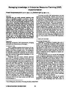
Fig. 1. In (a), the OctArm continuum manipulator grasps a traffic cone. Shown here, it replaces the end-effector of a Foster-Miller Talon robot. In (b), the two-section Air-Octor continuum robot is shown.
* This work was supported in part by the Defense Advanced Research Projects Agency (DARPA) Defense Sciences Office through the Space and Naval Warfare Systems Center, San Diego, Contract Number N66001-03-C-8043.
0-7803-9505-0/06/$20.00 ©2006 IEEE
1840
achieve full use of these robots, these couplings must be understood and exploited. This paper introduces a new and complete practical solution for the inclusion of actuator length limits in continuum robot kinematics. Almost all continuum designs to date are affected by actuator length limit problems. These designs can be divided into the three categories of continuum robots proposed by [10] of intrinsic, extrinsic, and hybrid actuation strategies. Intrinsically actuated continuum robots, typically featuring sections composed of three actuators mounted to a plate at each end which extend longitudinally, produce bending due to differences in the actuator lengths as shown in Fig. 2. Therefore, they are affected by actuator length limits due to minimum and maximum extension achievable by the three component actuators, which requires analysis to determine the resulting configuration and workspace of the robots. Robots in this category, which are partially drawn from [10], include the flexible micro-actuator [ 11 ], the AMADEUS hand [ 12 ], pizeohydraulic systems [13], the active hose [14], the EDORA colonoscope [15], the slim slime robot [16], shaped-memory alloy tentacles [17], and McKibben-based trunks [18]. Novel actuation schemes such as electrorheological fluid-based manipulators suggested by [19] and electrostrictive polymer artificial muscles suggested by [ 20 ] are likewise affected by maximum and minimum length limits. In variable-length continuum trunks, both extrinsic and hybrid actuation strategies utilize tendons such as steel cables or flexible plastic rods to shape the central member, or body, as diagrammed in Fig. 3. The body in an extrinsically-actuated robot is composed of an elastic, passive element such as a spring to provide tension on the tendons. For hybrid designs, the body is composed of actively-controlled bellows, such as pneumatically-pressurized tubes. In both designs, while the tendons can be made arbitrarily long by adding additional cable or flexible rod, the body is limited to a maximum and minimum length. Neither springs nor bellows can be extended beyond a maximum length without fracturing the springs or tearing the bellows material. Likewise, neither springs nor bellows can be compressed beyond some minimum length without causing similar damage. Therefore, actuator length limits in these designs apply to the body of a continuum robot
and are therefore termed central member length limits. Robots affected by these limits include a laryngeal surgery system [21], the slim slime robot with bridle bellows [22], the AirOctor trunk [23], the KSI tentacle [24], the Elastor manipulator [25], the tensor arm manipulator [26], the SPINE manipulator [27], and an elephant trunk type elastic manipulator [28]. An analysis of the statics which define the shape of continuum robots reveals that, in the absence of external forces such as gravity, continuum trunk sections bend with constant curvature due to the equal distribution of bending forces along the trunk [5]. Therefore, the model presented in [2] was chosen to define a single section of a continuum robot in terms of trunk length s , curvature N , and direction of curvature I as illustrated in Fig. 3. Each trunk section, therefore, possesses two degrees of bending freedom and one degree of freedom of extension. A multi-section trunk can then be formed by serially connecting several single sections. The analysis performed in this paper is based on this model and its assumption of constant curvature. The first section focuses on actuator length limits for intrinsically-actuated robots, while the following section analyzes the same problem for the extrinsic/hybrid actuation case. The analysis presented in this paper is essential to both enable continuum trunks to reach all points within their workspace and to grasp objects by encircling them with their trunks. For intrinsically-actuated trunks, this paper introduces new formulations for determining the maximum curvature N as defined in Fig. 3 and angle of wrap T shown in Fig. 4 achievable by the trunk over all directions of curvature. Likewise, it determines the maximum N and T achievable in a specific direction of curvature as illustrated by Fig. 6 and achievable at a specific direction of curvature and trunk length, which defines the trunk’s configuration space, in Fig. 7. For extrinsic and hybrid designs, it determines the range of trunk lengths and curvatures which can be physically achieved by these devices without damaging them. These contributions to the field of continuum robotics are unique to the best of the authors’ knowledge and represent essential knowledge required to effectively operate continuum robots. As such, the subsequent analysis has been necessary for the successful im-
l3 l1 l2
Fig. 3. Extrinsic and hybrid actuation schemes. Three tendons, labeled cable 1 to 3, of lengths l1�3, shape the robot. In the center, a passive backbone in the extrinsic case or a flexible actuator such as pneumatically pressurized tube in the hybrid case.
Fig. 2. Intrinsic actuation scheme. Three actuators are connected in parallel between two plates. Differences in length cause bending of the structure.
1841
plementation of two continuum robots shown in Fig. 1, OctArm and Air-Octor, in order to obtain practical use of these manipulators. II. DERIVATION OF ACTUATOR LENGTH LIMITS FOR INTRINSICALLY ACTUATED CONTINUUM ROBOTS
A. Limitations on whole-arm manipulation A strongly desired feature of a continuum trunk is its ability to manipulate objects within its workspace by grasping them. Although an end effector can be mounted on the tip of the robot, the trunk itself forms a versatile and powerful manipulator by wrapping itself around a desired item, much in the way a boa constrictor grasps its prey. This form of manipulation, termed whole-arm manipulation [1], relies on a trunk with sufficient flexibility to curl around on itself to form an enveloping grasp. A single-section grasp can be achieved by bending the trunk through a wrap angle of 360q; a twosection grasp, by bending each section through 180q ; and in 360q degrees. general an n-section grasp by bending through n Failing to achieve the curvature necessary to bend through the required number of degrees prevents the trunk from enveloping then grasping objects in this fashion. As the following analysis reveals, the inherent design of the pneumatic actuators powering the OctArm trunk [18] † , shown in Fig. 1, imposes a limit on how much the trunk can bend, significantly affecting its whole-arm manipulation abilities and restricting its workspace. Trunk length s, its direction of curvature I , and its amount of curvature N as defined by Fig. 3 are all affected by these limits. For example, as derived in the following paragraphs, this limitation varies with the direction I in which the trunk bends; it achieves maximum curvature N max when bending away from the location of any of the actuators, accomplishes a lower local maximum N 2 max when bending toward the location of any of the actuators, and varies in bending performance between these points as shown in Fig. 6. In the OctArm manipulator, the variation is large enough to prevent whole-arm grasping unless the trunk bends along its direction of maximum curvature. In addition, the amount of achievable curvature strongly depends on the trunk section length s . Simply choosing the length which produces maximum curvature away from the three actuator locations and using that length for all trunk orientations reduces the achievable curvature at other orientations by almost 50%, severely reducing the manipulator’s capabilities and workspace. A plot of the curvature achievable for a given trunk length in a given bending direction reveals a complex structure composed of a steep peak representing the maximum curvature achievable as shown in Fig. 7. Choosing a non-optimal trunk length results in “falling” off this peak by severely restricting achievable curvature. Physically, this means that if the arm is wrapped around an object initially at
maximum curvature, if the arm moves to rotate the object, the curvature enabling the grasp will decrease significantly (away from the curve peak), typically leading to the object being dropped! Fig. 6 illustrates results obtained when fixing trunk length at two different points, as opposed to the approach developed in our implementation based on the analysis in this paper of varying trunk length to obtain maximum curvature. B. Maximum curvature for specific configurations Examining equations given in [2], [7] which map a given trunk length s , curvature N , and direction of curvature I as defined in Fig. 3 to desired actuator lengths l1�3 illustrate this dependence between trunk length and achievable curvature. Two measures allow evaluation of the trunk’s ability to bend. The first measure is the maximum angle T which can be subtended by the trunk as it bends along the arc, termed the angle of wrap and illustrated in Fig. 4. When T 360q, the trunk can wrap entirely around an object to form a whole-arm grasp, while an angle of T 180q forms a half-wrap around an object to be grasped. The second measure is the trunk’s maximum 1 achievable curvature N , defined as N where r gives the r radius of the arc along which the trunk bends. The two are intimately related, because the angle subtended by an arc of 1 is given as T N s. Note that [7] length s and of radius r
N
reveals curvature N to be
N where g
2
g , d � l1 � l2 � l3
(1)
l12 � l2 2 � l32 � l1l2 � l2 l3 � l1l3 , and trunk length s as
s
nd � l1 � l2 � l3 g
§ g · sin �1 ¨ , ¨ 3nd ¸¸ © ¹
(2)
which allows computation of the angle of wrap T as their product, yielding
r 10
T
90q
N
1 10
†
We adopt the case of the continuum robots introduced in [7] and [18] as examples in this paper. However, the issues apply across the spectrum of existing continuum robot designs as noted in the introduction.
Fig. 4. Example of curvature and angle of wrap. The curvature is N the angle of wrap is T 90q.
1842
0.1 and
§ g · 2n sin �1 ¨ . ¨ 3nd ¸¸ © ¹
T
Therefore, actuator length can be rewritten as
(3)
li
Examination of (1) and (3) shows that both angle of wrap and curvature are functions of differences in actuator lengths. The trunk is straight �T N 0 when the actuators are equal in length, while maximum curvature N max and angle of wrap T max are achieved when the actuators are maximally different in length. Given physical actuators which are limited to a minimum and maximum length, notated lmax and lmin , maximum curvature N max therefore occurs when two actuators are at their minimum length lmin and one is at its maximum length lmax , producing
N max
2
lmax � lmin . d � lmax � 2lmin
2
lmax � lmin . d � 2lmax � lmin
using the identity T
§l �l · 2n sin �1 ¨ max min ¸ , © 3nd ¹
> � sin I
T
i 1!3
choosing the actuator for which f min �I
(5)
N Noting that T of wrap,
§S · sin ¨ � I ¸ 3 © ¹
min f i �I to have
i 1!3
T
C. Maximum achievable curvature in an arbitrary direction of curvature I To find the maximum achievable curvature at a given desired direction of curvature I , first recall that maximum curvature is produced by maximum actuator length differences. Therefore, in a three actuator system (which is typical of a wide range of continuum robot hardware implementations), maximum curvature occurs when two actuators take on values of lmax and lmin while the third actuator length varies in order to meet the constraint of bending at in the direction I . Repeating equations developed in [2], [8], ª º « » s �1 � N d sin I « » « § §S ··» « s ¨1 � N d sin ¨ � I ¸ ¸ ». ©3 ¹¹» « © « » « s §1 � N d cos § S � I · · » ¨ ¸ ¸» «¬ ¨© ©6 ¹ ¹¼
li � s . sdfi
(8)
N s yields the equivalent expression for angle
(6)
showing that while N max achieves a smaller grasping radius than N 2 max, both positions wrap through the same angle. However, as shown above, this maximum curvature can only be achieved in three specific configurations, namely l1�3 ^� lmax , lmax , lmin , � lmax , lmin , lmax , and � lmin , lmax , lmax `. Similarly, a second local maximum can only be achieved at l1�3 ^� lmax , lmin , lmin , � lmin , lmax , lmin , and � lmin , lmin , lmax `.
ª l1 º «l » « 2» «¬l3 »¼
N s , where f �I
(7)
§S ·º � cos ¨ � I ¸» . Guaranteeing that one actuator length re6 © ¹¼ mains in the range of valid lengths >lmin , lmax @ while fixing the other two at lmax and lmin requires a careful mapping of these lengths to particular actuators. Specifically, choosing the actuator for which f max �I max f i �I to have length lmax and
Evaluating these two cases in terms of angle of wrap T yields
T
s � T dfi �I
length lmin demonstrates that (7) can be bounded as lmin d lmid s �1 � N df mid d lmax, guaranteeing that the remaining actuator’s length lmid is valid. The conditions necessary to achieve the maximum curvature N max �I at a desired angle I can then be determined by solving (7) for curvature to produce
(4)
A second local maximum curvature is likewise obtained by choosing one actuator to be of length lmax and the remaining two actuators to be of length lmin , producing a curvature of
N 2 max
s �1 � N df i �I
li � s . df i
(9)
Evaluating (8) and (9) at the points � lmax , f max and � lmin , f min yields lmax � s sdf max
N max �I T max �I
lmax � s df max
lmin � s and sdf min
(10)
lmin � s , df min
(11)
demonstrating that this maximum curvature at I can only be achieved at a specific trunk length sN max �I obtained by solving either equation for s as sN max �I
f max lmin � f min lmax . f max � f min
(12)
Substituting this result into (10) and (11) reveals the maximum curvature and angle of wrap achievable at an angle I given the optimal trunk length specified by (12) is
N max �I
lmax � lmin and d � f max lmin � f min lmax
(13)
lmax � lmin . d � f max � f min
(14)
T max �I
Therefore, the absolute maximum curvature determined in (4) occurs at I ^30q,150q, 270q` with two actuators at lmin and one at lmax while the second local maximum given in (5) with
1843
0.24
two actuators at lmax and one at lmin occurs at I ^90q, 210q,330q`. Between these six points, in our implementation and based on the analysis herein, one actuator is fixed at lmax , a second actuator at lmin , and the third actuator’s length varies due to the changing trunk length s as shown in Fig. 5. This configuration achieves the maximum possible curvature N at the desired direction of curvature I as illustrated by Fig. 6 and the maximum possible angle of wrap T at the desired I .
Curvature κ (in cmí1)
C. Maximum curvature at an arbitrary direction of curvature I and trunk length s Fig. 6 also illustrates how essential correct trunk length s is to produce maximum curvature. The maximum achievable curvature N given a desired direction of curvature I and fixed trunk length s, plotted in Fig. 7, can be determined by examining (8), noting that only one free variable, li, remains. As before, choosing li lmax when fi f max or li lmin when fi f min produces the maximum cable length difference given the other two cable lengths are fixed by the given trunk length s and direction of curvature I . The two possible solutions are there l � s lmin � s ½ , fore ® max ¾. However, only the solution which re¯ sdf max sdf min ¿ spects the relationship between trunk length and actuator length limits can be used; for example, choosing s lmax requires choosing li lmax. The valid region for each of the two solutions can be determined by observing that an achievable curvature is limited by the maximum possible curvature determined in (13), so that
0.22
0.18 0.16 0.14
sκmax varies with φ s fixed at κmax
0.12
s fixed at κ2max 0.1 0
100 150 200 250 300 350 Direction of curvature φ (in degrees) Fig. 6. Trunk maximum curvature N max �I determined by evaluating (13), shown in a dotted red line as the direction of curvature I varies. Dashed blue line and solid green line illustrate the effects of fixing trunk length s, determined by evaluating (15). Trunk minimum actuator length was lmin 25 cm and maximum actuator length is lmax 35 cm for a trunk of radius d 1 cm.
50
Solving for s by substituting in the N max given in (13) produces f l � f min lmax when two inequalities similar to (12), s d max min f max � f min f l � f min lmax choosing lmax and f max or s t max min when choosing f max � f min lmin and f min. Summarizing, the maximum achievable curvature N max �I , s at a specified trunk length s and direction of curvature I is therefore
lmax � s for some valid s ° sdf ° N max �I t ® max ° lmin � s for other valid s. °¯ sdf min
N max � s, I
f l � f min lmax lmax � s when s t max min ° sdf f max � f min ° max ® f l � f min lmax � l s ° min when s d max min . °¯ sdf min f max � f min
(15)
This equation defines the configuration space of the trunk. Similar results for T max � s, I can be obtained by repeating the process with (9) for the limits given in (14).
31.5 31 30.5 s (cm)
0.2
30 29.5 29 28.5 0
50
100
150 200 I (degrees)
250
300
350
s chosen as sN max s fixed to achieve N max s fixed to achieve N 2 max
Fig. 5. Varying trunk length sN
max
�I , determined by evaluating (12), neces-
sary to achieve maximum curvature illustrated in Fig. 6, versus fixed trunk lengths which achieve maximum curvature at certain locations. Trunk minimum actuator length was lmin 25 cm and maximum actuator length was lmax 35 cm for a trunk of radius d 1 cm.
C. Analysis of actuator length limits Plotting (15) produces the graph shown in Fig. 7. As expected, the plot contains six peaks, three maxima at I ^30q,150q, 270q` and three secondary local maxima at I ^90q, 210q,330q` . Viewed from the left side, so that I is visible along the bottom axis and N extends vertically upwards, produces a plot identical to Fig. 6. The peak of the curve shows the maximum possible curvature at a given I , also plotted as the dotted red line of Fig. 6 as trunk length is varied as shown in Fig. 5. Likewise, viewing the graph from on top so that only s and I are visible reveals the plot shown in Fig. 5. The sharpness of the peaks in Fig. 7 indicates that maximum possible curvature N at a particular I can only be obtained by a precise choice of s; varying s only a little causes a dramatic drop in the achievable curvature N . Lab experiments confirm that manually varying trunk length s to achieve
1844
The limitation on trunk curvature N , with respect to trunk length s, is similarly present in continuum trunks that are capable of extension and retraction. These limits are present due to the physical limits on extension and retraction length of the central member that are present in this class of variable-length manipulators. Fortunately, the N limit is not also dependent upon the direction of curvature I , as is the case for intrinsicactuated trunks, because of the symmetrical nature of the central member of continuum trunks. In the following analysis, we will refer to the length at which the central member is maximally extended as sm, and the length at which the central member is maximally retracted as sl. These are the length limits that no part of the trunk can exceed without damaging the structure of the manipulator.
ț (cm-1)
0.2 0.15 0.1 0.05 0 26 28 s (cm)
30 32 34
350
300
250
200
150
100
50
0
A. Trunk length s limits at an arbitrary curvature ț. At zero curvature, N 0, the length limits trivially necessitate that sl d s d sm. Physically, this means the central trunk length must stay within the length limits. However, the implications of the length limits are more complicated when the trunk is a bent configuration N z 0, as illustrated in Fig. 9. When in a bent configuration, the trunk is not at a uniform length throughout. This fact can be seen in Fig. 9, by the labeled lengths sin, s, and sout, where sin � s � sout. The trunk parameter s is defined as the length of the trunk at the center of the central member. Defining sin as the shortest section of the trunk and sout as the longest section of the trunk, it is apparent that these sections of the trunk are affected by the length limits sl and sm, respectively. The limiting effects on the trunk parameter s can be mathematically determined by using the constant curvature assumption and the definition of arc length, T sN where
I (degrees)
Fig. 7. Configuration space of an intrinsically-actuated trunk. Maximum achievable trunk curvature N max � s, I at a given direction of curvature I and trunk length s computed by applying (15). Results were obtained for a trunk where maximum an minimum actuator lengths are lmax = 35 cm, lmin = 25 cm and the trunk radius is d 1 cm.
the maximum curvature N necessary to whole-arm grasp an object by encircling it with a trunk section is extremely difficult, necessitating the use of automatic control of trunk length. Fig. 8 illustrates the results shown in Fig. 7 from another perspective, showing the effect that trunk length s has on curvature N . The plots were formed by first bending a singlesection trunk at the angle I 60q as much as possible given the trunk length chosen as indicated in the legend for a singlesection trunk, then by sweeping the trunk from I >30q,150q@ to produce a surface. The trunk bends downward from the origin of the coordinate system, located at the base of the arrows that label I . Plot (a) shows that, by choosing s and N from (12) and (13), the trunk achieves almost a full 360q of wrap T , forming a circle, regardless of the angle I chosen. The radius of the circle changes as trunk length changes, due to actuator length limits. Therefore, these equations enable whole-arm grasping at any angle by appropriately varying trunk length to form an encircling grasp. In contrast, simpler approaches form an encircling grasp only at specific points. Plot (b) illustrates the effects of fixing trunk length to achieve the maximum curvature defined by (4). Therefore, the trunk forms an encircling grasp only at I ^30q,150q, 270q` , as discussed earlier. The first two points of I ^30q,150q` are shown in the figure. Likewise, plot (c) illustrates the effects of fixing trunk curvature to achieve the second local maximum given in (5); an encircling grasp can only be formed at I ^90q, 210q,330q`, of which the point I 90q is shown in the plot. Plot (d) combines all three, showing that the tightest curvature is achieved in (a), second tightest in (b), and least tight in (c). III. DERIVATION OF CENTRAL MEMBER LENGTH LIMITS FOR EXTERNAL AND HYBRID ACTUATION SCHEMES
90 60
120
120
30
150
90
60 30
150
(a)
(c)
90 60
120
120
150
30
90 60 30
150
(d)
(b) s chosen as sN max s fixed to achieve N max s fixed to achieve N 2 max
Fig. 8. A plot of the surface formed by rotating the trunk, drawn at I 60q from I >30q,150q@. Plot (a) was formed by choosing s sN max �I from (12) and N N max �I from (13). Plot (b) was formed by fixing s to achieve N max as defined in (4), and plot (c) by fixing s to achieve N 2max as defined by (5). The trunk bends into a circle of varying radius based on actuator length limits of lmin 25 cm and lmax 35 cm. Trunk diameter is d 1 cm.
1845
r
ș
1
rout
k
�
1
rin
k
1
d
k
2
�
d 2
d 2
sin
s sout
Fig. 10. Upper and lower limits on trunk length s from (16) and (17), as trunk curvature N is varied ț. Plot is based on central member length limits of sm 30 cm, sl 10 cm, and diameter d 3 cm. Note that it is physically
Fig. 9. Central member of the trunk in a bent configuration.
1 1 d . Therefore, sout T rout where rout � and d is the r N 2 diameter of the trunk section, as shown in Fig. 9. Through substitution, the limit can be expressed as
N
sout
§1 d· � ¸ ©N 2 ¹
T¨
� sN §¨
1
©N
�
d· ¸ 2¹
impossible to achieve N >0.333 cm and that maximum achievable curvature occurs at s
Similarly using sin
sm § Nd · ¨1 � ¸ 2 ¹ ©
T rin and rin
be derived as st
.
(16)
§ sm ·§ 2 · � 1¸ ¨ ¸ N m and © s ¹© d ¹
Nd ¨
§ ©
(20)
sl � sm ½ 2 °° . ¾ sl � sm d s d sm ° °¿ 2
sl d s d
(21)
IV. RESULTS AND CONCLUSIONS .
(17)
B. Curvature limits ț at an arbitrary trunk length s As the values for sin and sout vary depending upon the trunk’s curvature ț, it follows that the central member length limits (sm and sl) also have a limiting effect on the trunk parameter ț. This can be seen analytically as the s limits are dependent upon ț. This effect can be determined by solving (16) and (17) for ț, which gives
N d ¨1 �
20 cm.
°°N l , N d® °N , °¯ m
d � , the lower limit can N 2
§ Nd · ¨1 � ¸ 2 ¹ ©
( sm � sl )
because the smaller of țl or țm gives the physical limit. Which one is the smallest depends upon the current s configuration the trunk. The țl term is smaller if s is closer to sl than sm. Correspondingly, the țm term is smaller if s is closer to sm than sl. Therefore, (20) can be rewritten as
1
sl
2
N d min(N l , N m ),
§ Nd · s ¨1 � ¸ d sm . 2 ¹ ©
Solving this expression for s provides an expression for the upper limit on s, sd
1
sl · § 2 · ¨ ¸ Nl , s ¸¹ © d ¹
(18)
(19)
where țm is the limit due to sm and țl is the limit due to sl. Therefore, the ț limit should be expressed as
1846
The analysis presented in this paper overcomes key implementation problems unique to continuum robots, due to actuator and central member length limits which necessarily constrain and shape the joint or configuration space within which continuum robots must operate. The analysis applies to intrinsic, extrinsic, and hybrid actuation schemes, where it can be used to improve the performance of a wide range of existing continuum robots. It determines the effects of these length limits on the configuration space, as shown in Fig. 7 and Fig. 10, and provides methods for choosing manipulator configurations which enable the trunk to safely reach all points within this space, allowing operators to successfully perform wholearm grasping. For example, by properly coupling trunk length with the direction of curvature and desired curvature via (12), the operator is no longer burdened with the complexity of manually choosing the optimal trunk length shown as the peak in Fig. 7 and can obtain the maximum possible curvature, and therefore whole-arm grasping ability, the robot is capable of. Experiments in the lab have clearly shown that hand-tuning length to obtain maximum curvature to be difficult, time-consuming,
and distracting from the primary objective of manipulating an object. Additionally, the central member length limits analysis allow for the recognition of physical limits of a variable-length continuum trunk manipulator that may not be immediately obvious. By recognizing and defining the physical limits, a control system can be developed that prevents the trunk from attempting to move into configurations that can cause physically damage to the manipulator. REFERENCES [1] [2] [3] [4] [5] [6] [7] [8] [9] [10] [11]
[12]
[13] [14]
[15]
[16] [17]
K. Salisbury, W. Townsend, B. Ebrman, D. DiPietro, “Preliminary design of a whole-arm manipulation system (WAMS),” Proc. IEEE Intl. Conf. on Robotics and Automation, April 1988, vol. 1, pp. 254 – 260. B. A. Jones and I. D. Walker, “Kinematics for multi-section continuum robots,” IEEE Trans. Robotics, accepted. S. Hirose, Biologically inspired robots, Oxford University Press, 1993, pp. 20–30. G. S. Chirikjian and J. W. Burdick, “A modal approach to hyperredundant manipulator kinematics,” IEEE Trans. on Robotics and Automation, vol. 10, no. 3, June 1994, pp. 343–354. I. A. Gravagne and I. D. Walker, “Large deflection dynamics and control for planar continuum robots,” IEEE/ASME Trans. on Mechatronics, vol. 8, no. 2, June 2003, pp 299–307. M. W. Hannan and I. D. Walker, “Kinematics and the implementation of an elephant’s trunk manipulator and other continuum style robots,” Journal of Robotic Systems, vol. 20, no. 2, Feb. 2003, pp. 45–63. B. A. Jones, W. McMahan, and I. D. Walker, “Design and analysis of a novel pneumatic manipulator”, Proc. of 3rd IFAC Symposium on Mechatronic Systems, Sydney, Australia, Sept. 2004, pp. 745–750. W. McMahan, B. A. Jones, I. Walker, V. Chitrakaran, A. Seshadri, and D. Dawson, “Robotic manipulators inspired by cephalopod limbs”, Proc. CDEN Design Conf., Montreal, Canada, 2004, pp. 1–10. B. A. Jones and I. D. Walker, “A New Approach to Jacobian Formulation for a Class of Multi-Section Continuum Robots,” Proc. IEEE Intl. Conf. on Robotics and Automation, Barcelona, Spain, 2005, pp. 3279–3284. G. Robinson and J. B. C. Davies, “Continuum robots – a state of the art,” Proc. 1999 IEEE Intl. Conf. on Robotics and Automation, Detroit, Michigan, May 1999, vol. 4, pp. 10–15. K. Suzumori, S. Iikura, and H. Tanaka, “Development of flexible microactuator and its applications to robotic mechanisms,” Proc. IEEE Intl. Conf. on Robotics and Automation, Sacramento, California, April 1991, vol. 2, pp. 1622–1627. D. M. Lane, J. B. C. Davies, G. Robinson, et al., “The AMADEUS dexterous subsea hand: design, modeling, and sensor processing – fingers made from three hydraulic tubes,” IEEE Journal of Oceanic Engineering, vol. 24, no. 1, pp. 96–111, Jan. 1999. P. Kallio, M. Lind, Q. Zhou, and H. N. Koivo, “A 3-DOF piezohydraulic parallel micromanipulator,” Proc. IEEE Intl. Conf. on Robotics and Automation, Leuven, Belgium, May 1998, vol. 2, pp. 1823–1828. H. Tsukagoshi, A. Kitagawa, and M. Segawa, “Active hose: an artificial elephant's nose with maneuverability for rescue operation,” Proc. IEEE Intl. Conf. on Robotics and Automation, Seoul, Korea, May 2001, vol. 3, pp. 2454–2459. G. Chen, M. T. Pham, T. Redarce, C. Prelle, and F. Lamarquem, “Design and modeling of a micro-robotic manipulator for colonoscopy,” Proc. 5th Intl. Workshop on Research and Education in Mechatronics, Annecy, France, June 2005, to appear. H. Ohno and S. Hirose, “Design of slim slime robot and its gait of locomotion”, Proc. IEEE/RSJ Intl. Conf. on Intelligent Systems, Maui, Hawaii, Oct. 2001, vol. 2, pp. 707–715. M. Ivanescu, N. Bizdoaca, and D. Pana, “Dynamic control for a tentacle manipulator with SMA actuators,” Proc. IEEE Intl. Conf. on Robotics and Automation, Taipei, Taiwan, May 2003, vol. 2, pp. 2079–2084.
1847
[18] M. B. Pritts and C. D. Rahn, “Design of an artificial muscle continuum robot,” Proc. IEEE Intl. Conf. on Robotics and Automation, New Orleans, Louisiana, April 2004, vol. 5, pp. 4742–4746. [19] M. Ivanescu, and V. Stoian, "A Variable Structure Controller for a Tentacle Manipulator", Proc. IEEE Intl. Conf. Robotics and Automation, Aichi, Japan, May 1995, vol. 3., pp. 3155–3160. [20] R. Kornbluh, R. Pelrine, J. Eckerle, and J. Joseph, “Electrostrictive polymer artificial muscle actuators,” Proc. IEEE Intl. Conf. on Robotics and Automation, Leuven, Belgium, May 1998, vol. 3, pp. 2147–2154. [21] N. Simaan, “Snake-like units using flexible backbones and actuation redundancy for enhanced miniaturization,” Proc. IEEE Intl. Conf. on Robotics and Automation, Barcelona, Spain, April 2005, pp. 3023–3028. [22] T. Aoki, A. Ochiai, and S. Hirose, “Study on slime robot,” Proc. IEEE Intl. Conf. on Robotics and Automation, New Orleans, April 2004, pp. 2808–2813. [23] W. McMahan, B. A. Jones, and I. D. Walker, “Design and Implementation of a Multi-Section Continuum Robot: Air-Octor,” IEEE/RSJ Intl. Conf. on Intelligent Robots and Systems, August 2005, Edmonton, Canada, to appear. [24] G. Immega and K. Antonelli, “The KSI tentacle manipulator,” Proc. IEEE Conf. on Robotics and Automation, Nagoya, Japan, May 1995, vol. 3, pp. 3149–3154. [25] S. Hirose, Biologically inspired robots, Oxford University Press, 1993, pp. 147–155. [26] V. C. Anderson and R. C. Horn, “Tensor arm manipulator design,” Trans. ASME, vol. 67-DE-57, pp. 1–12, 1967. [27] A. Morecki and J. Knapczyk, ed., Basics of Robotics: Theory and Components of Manipulators and Robots, International Center for Mechanical Sciences (CISM) Courses and Lectures no. 402, Springer-Verlag, 1999, pp. 500–501. [28] R. Cieslak and A. Morecki, “Elephant trunk type elastic manipultor – a tool for bulk and liquid type materials transportation,” Robotica, vol. 17, 1999, pp. 11–16.