Precise Semantics of EMF Model Transformations by Graph Transformation Enrico Biermann1 , Claudia Ermel1 , Gabriele Taentzer2 1 2
Technische Universit¨at Berlin, Germany, {enrico,lieske}@cs.tu-berlin.de Philipps-Universit¨at Marburg, Germany
[email protected]
Abstract. Model transformation is one of the key activities in model-driven software development. An increasingly popular technology to define modeling languages is provided by the Eclipse Modeling Framework (EMF). Several EMF model transformation approaches have been developed, focusing on different transformation aspects. To validate model transformations wrt. functional behavior and correctness, a formal foundation is needed. In this paper, we define EMF model transformations as a special kind of typed graph transformations using node type inheritance. Containment constraints of EMF model transformations are translated to a special kind of EMF model transformation rules such that their application leads to consistent transformation results only. Thus, we identify a kind of EMF model transformations which behave like algebraic graph transformations. As a consequence, the rich theory of algebraic graph transformation can be applied to these EMF model transformation to show functional behavior and correctness. We illustrate our approach by selected refactorings of simplified statechart models.
Keywords: model-driven software development, Eclipse Modeling Framework, model transformation, graph transformation.
1
Introduction
Model-driven software development is considered as a promising paradigm in software engineering. Models are ideal means for abstraction and enable developers to master the increasing complexity of software systems. Since models are central artifacts in modeldriven software development, the quality of generated software is directly dependent on the quality of models. Modifying models (i.e. performing model refactoring [11]) to improve the understandability and refine the model structure is an important part of model development. Throughout this work, we use model refactoring as an example for precisely specifying model transformations. The Eclipse Modeling Framework (EMF) [6] has evolved to one of the standard technologies to define modeling languages. EMF provides a modeling and code generation framework for Eclipse applications based on structured data models. The modeling approach is similar to that of MOF, actually EMF supports Essential MOF (EMOF) as part of the OMG MOF 2.0 specification [12]. Containment relations, i.e. aggregations, define an ownership relation between objects. Thereby, they induce a tree structure in model instantiations. In MOF and EMF,
2
this tree structure is further used to implement a mapping to XML, known as XMI (XML Meta data Interchange) [14]. Containment always implies a number of constraints for model instantiations that must be ensured at run-time. As semantical constraints for containment edges, the MOF specification [12] states the following: – ”An object may have at most one container.” – ”Cyclic containment is invalid.” As mentioned earlier, EMF provides full implementations of instance models. These implementations always ensure these constraints. A third constraint may be useful for storing EMF models: ”There is a distinguished object, the root object, which contains (transitively) all other model objects.” Model-driven development relies heavily on model transformations. EMF models can be manipulated by several approaches to rule-based model transformations. A transformation framework for EMF models which follows the concepts of algebraic graph transformation [7] as far as possible, is presented in [4]. But EMF model transformation does not always behave like algebraic graph transformation. The main reason is the difficulty to always satisfy the containment constraints of EMF. In this paper, we define EMF models as typed graphs with containment edges. We identify a kind of model transformation rules which lead to consistent EMF model graphs, if applied as normal graph transformation rules to consistent EMF model graphs. Thus, we identify a kind of EMF model transformations which behave like algebraic graph transformations. The advantage of this approach is that we can apply the rich theory of algebraic graph transformation to EMF model transformations for validation. Our approach is illustrated by selected refactorings of simplified statechart models. The abstract syntax definition of statechart models mostly follows that in the UML2 EMF model [8], but does not consider regions, state actions, and structured transition inscriptions. Thus, we concentrate on the main statechart structure. Structural improvements of statecharts models might comprise a number of refactoring steps. The theory provided by graph transformation helps us to identify a certain refactoring order by analyzing dependencies between refactoring rules. Moreover, refactoring steps might be in conflict to each other. Here, the graph transformation theory is helpful in analyzing conflicts between refactoring rules, based on the so-called critical pair analysis (see also [10]). Last but not least, a complex refactoring cannot be realized by just one rule. Therefore, termination is another issue which will be shown by checking sufficient termination criteria.
2
EMF Models as Graphs
In this section, we start to lay the basis for the application of graph transformation theory to EMF model transformations. As first step, we consider EMF instance models3 as typed graphs with containment edges. Typing is expressed by a so-called type graph. It has some similarities to a metamodel, but does not contain multiplicities and other constraints. Those have to be expressed by graph constraints, as done in [13]. 3
Note that the EMF community uses the terms “EMF model” for metamodel and “EMF instance model” for a model conforming to a metamodel.
3
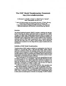
Since containment plays a special role in EMF models, we distinguish a special kind of edge types defining containments. For being able to check for containment cycles later, we identify containment types (called cycle-capable) which may be part of containment cycles, summarized in CCycle 4 . Type graphs with containment types are called sound, if there is a root type which transitively contains all other concrete types. Definition 1 (Graph). A graph G = (GN , GE , sG , tG ) consists of a set GN of nodes, a set GE of edges, as well as source and target functions sG , tG : GE → GN . Definition 2 (Type graph). A type graph T G = (T, I, A, C) consisting of graph T = (N, E, s, t), a graph I, called inheritance graph sharing the same set of nodes N with T (but not the edges), a set A ⊆ N of abstract nodes, and a set C ⊆ E of containment edges. For each node n in I the inheritance clan is defined by clanI (n) = {n0 ∈ N | ∗ ∃ path n0 −→ n in I} where path of length 0 is included, i.e. n ∈ clanI (n). Furthermore we define a containment relation5 containsT G = {(n, m) ∈ N × N | ∃c ∈ C ∧ x, y ∈ N : s(c) = x with n ∈ clan(x) ∧ t(c) = y with m ∈ clan(y)} ∪ {(x, y) ∈ N × N | ∃z ∈ N : (x containsT G z ∧ z containsT G y)} Based on containsT G we create the equivalence relation equivcontains = r(containsT G ) − {(x, y) ∈ containsT G |(y, x) ∈ / containsT G }. with r being the reflexive closure of containsT G . Then we define CCycle = {c ∈ C|∃vs ∈ clan(s(c)) ∧ ∃vt ∈ clan(t(c)) : (vs , vt ) ∈ equivcontains } as a subset of cycle-capable containment edges that might be part of containment cycles. Type graph T G is called sound, if there is a type node r ∈ N − A, called root type, such that the following holds: ∀n ∈ N − A − {r} : (r, n) ∈ containsT G Example 1 (EMF model for simplified statecharts). In the running example, we consider the refactoring of a simplified form of statecharts. In Fig. 1 an EMF model for a simplified statecharts variant is shown. Events, actions, and parallel regions are not shown. Nevertheless, this model is very interesting from the containment point of view: This type graph is sound, since type StateM achine contains all concrete types, i.e. is the root type. It is obvious that type V ertex is contained in StateM achine as well as in State. Since State inherits from V ertex, it is again contained in State. Due to the same reason, P seudostate is contained in State. Moreover, T ransition and F inalState are contained in State. Please note that N amedElement is abstract and does not have to be contained in the root type. The containment edge of types superState subState can be part of containment cycles because a State is either the source of the edge or it is in the clan of V ertex (the target of the edge). The pairs (State, State) as well as (State, F inalState) and (F inalState, State) are in the equivalence relation. Thus, a State (F inalState) may contain States (F inalStates) and form containment cycles. 4
5
The cycle-capable containment types would be the containment loops in a flattened type graph without inheritance. If there is no confusion, we use infix notation for containsT G , e.g. (x containsT G y) instead of (x, y) ∈ containsT G .
4
Please note that the multiplicities shown in Fig. 1 are not formalized by type graphs, but have to be expressed by additional graph constraints [13] (not shown here).
Fig. 1. EMF model for simplified statecharts
Now we are ready to define EMF models as typed graphs such that each object node has at most one container and no containment cycles do occur. Graphs which fulfill these requirements are called graphs with containment. Although EMF models do not need to be rooted in general, this property is important for storing them or more general, to define the model’s extent. Definition 3 (Typed Graph). Given a type graph T G = (T, I, A, C) and a graph G. Graph G is typed over T G, written type : G → T G, if for all e ∈ GE holds typeGN ◦sG (e) ∈ clanI (sT ◦typeGE (e)) and typeGN ◦tG (e) ∈ clanI (tT ◦typeGE (e)). type is called a clan morphism. It is called concrete if ∀n ∈ GN : typeGN (n) 6∈ A. Given a second clan morphism type0 : G → T G, type0 is finer than type, if type0GN (n) ∈ clanI (typeGN (n)) for all n ∈ GN and type0E = typeE . Definition 4 (Graph with containment (C-graph)). A graph with containment, short C-graph, is a graph G with a distinguished set of containment edges GC ⊆ GE . The containment edges induce the following transitive binary relation containsG : – containsG = {(x, y) ∈ GN × GN | ∃e ∈ GC : (sG (e) = x ∧ tG (e) = y) } ∪ {(x, y) ∈ GN × GN | ∃z ∈ GN : (x containsG z ∧ z containsG y)} All containment edges must fulfill the following properties (containment constraints): – e1 , e2 ∈ GC : tG (e1 ) = tG (e2 ) ⇒ e1 = e2 (at most one container). – (x, x) ∈ / containsG for all x ∈ GN (no containment cycles). If G is typed over T G = (T, I, A, C), there is a clan morphism type : G → T G which is consistent with containment, i.e. ∀e ∈ GC : typeGE (e) ∈ C Please note that the type graph T G is no C-graph.
5
Definition 5 (Rooted graph). A C-graph G is called rooted, if there is a node r ∈ GN , called root node, such that ∀x ∈ GN with x 6= r : r containsG x. Example 2 (EMF instance model). Fig. 2 shows the main parts of a simple statechart modeling a phone. The containment can be well seen in the tree-like representation. However, source and target states of transitions are not shown in the tree view, but in a separate properties view (at the right bottom). It shows the properties of transition “caller hangs up” from state “DialTone” to state “Idle”. In addition, a purely graphical view of the same statechart is depicted on the right which is especially helpful to understand the transition structure inside of state “Phone”. This instance model fulfills both containment constraints and is rooted by a node of type “StateMachine”.
Fig. 2. EMF instance model of a simple phone
In this paper, we concentrate on the structural issues of EMF models and their formalization. Needless to say that objects also may have typed attributes. They can be formalized by attributed graphs as done in [7]. For the application of graph transformation theory presented in Section 5, attributes will play a minor role.
3
EMF Transformation Rules as Consistent Graph Rules
In this section, we start to define a special kind of graph transformation which formalizes a form of EMF model transformation leading always to EMF models consistent with typing and containment constraints. For that purpose, the form of allowed transformation rules has to be restricted. Consistent transformation rules allow the following kinds of actions which change containments: 1. Delete an object node with its containment relation. 2. Create a new object node and connect it immediately to its container. 3. Delete a containment relation together with its contained object node or change the container.
6
4. Create a containment relation with the contained object node or change the container. 5. Create cycle-capable containment edges only, if the old and the new container are both transitively contained in the same container. Before we are able to precisely define consistent graph rules, we have to define relations between typed C-graphs, so-called C-graph morphisms. They define mappings of nodes and edges respectively, such that they are compatible with typing, source, and target functions. C-graph morphisms are needed to define graph rules such that the left (LHS) and the right-hand sides (RHS) are specified as well as the mapping from left to right. While the LHS defines the pattern to be found in the model, its relation to RHS formulates the actions to be performed. All object nodes and edges which occur in LHS but not in RHS are deleted, while all elements occurring in the RHS and not in the LHS are newly created. Elements occurring in both LHS and RHS have to be identified but are not changed. Moreover, negative application conditions (NACs) can be formulated. A NAC consists of an extension of the LHS where the structure not being part of the LHS is prohibited to occur in the model. Definition 6 (C-graph morphism). Given two C-graphs G, H, a pair of functions (fN , fE ) with fN : GN → HN and fE : GE → HE forms a valid C-graph morphism f : G → H, if it has the following properties: – fN ◦ sG (e) = sH ◦ fE (e), fN ◦ tG (e) = tH ◦ fE (e), and – ∀e ∈ GC ⇒ fE (e) ∈ HC (containment edges are preserved). If G and H are typed over T G, f must be type compatible, i.e. typeG = typeH ◦ f . If fN and fE are inclusions, then G is called a subgraph of H, denoted by G ⊆ H. Definition 7 (Graph rule). A graph rule typed over a type graph T G = (T, I, A, C) is given by p = (L ⊇ K ⊆ R, type, N AC), where L, K and R are C-graphs, type is a triple of typing clan morphisms type = (typeL : L → T G, typeK : K → T G, typeR : R → T G), and N AC is a set of pairs naci = (Ni , typeNi ), i ∈ N with L ⊆ Ni , and typeNi : Ni → T G a typing clan morphism, such that the following conditions hold: 1. typeL ⊇ typeK ⊆ typeR 0 0 2. typeRN (RN ) ∩ A = ∅ where RN := RN − KN , and 3. typeNi is finer than typeL for all (Ni , typeNi ) ∈ N AC The conditions in Def. 7 are due to the use of abstract types for rule elements and express that: 1. Retyping of elements is not allowed. 2. Newly created object nodes must be concretely typed. 3. Node types occurring in NACs may be finer than in the LHS. In the following definition, we formalize all actions that preserve consistent containment relations which have been described in the beginning of this section.
7 0 Definition 8 (Consistent graph rule). Let RC := RC − KC , L0N := LN − KN and 0 LC := LC − KC . A graph rule p = (L ⊇ K ⊆ R, type, N AC) is consistent wrt. containment if the following constraints are satisfied:
1. (node deletion) ∀n ∈ L0N : ∃e ∈ L0C with tL0C (e) = n, 0 0 2. (node creation) ∀n ∈ RN : ∃e ∈ RC with tR (e) = n, 3. (containment edge deletion) ∀e ∈ L0C with tL (e) = n: 0 n ∈ L0N ∨ (n ∈ KN ∧ ∃e0 ∈ RC with tR (e0 ) = n) 0 4. (containment edge creation) ∀e ∈ RC with tR (e) = n: 0 n ∈ RN ∨ (n ∈ KN ∧ ∃e0 ∈ L0C with tL (e0 ) = n) 5. (creation of cycle-capable containment edges) 0 ∀e ∈ RC with s(e) = n ∧ t(e) = m : ∃e0 ∈ L0C with s(e0 ) = o ∧ t(e0 ) = m : ((o, n) ∈ containsL ∧ (m, n) ∈ / containsL ) ∨ (n, o) ∈ containsL Example 3 (Refactoring rules). In Figures 3 to 5, we show three statecharts refactorings specified as EMF rules. Please note that object nodes with the same number mean that they are equal. The first one in Fig. 3 removes an isolated state from a composite state. Isolated means that no state or transition is contained and no transition starts or ends at this state. These constraints are guaranteed by the so-called dangling condition which allows the application of a graph transformation rule only if no edges are connected to nodes which are deleted by the rule (see Def. 9). This rule is consistent, since the isolated state node is deleted together with its containment edge.
Fig. 3. Refactoring “Remove isolated state”
Two transitions with the same source, the same target, and the same name are considered as redundant and can be removed by the graph rule in Fig. 4. This rule is consistent, since the redundant transition node is deleted together with its containment edge. The third refactoring folds two transitions with the same name if the original target states are contained in the same super state. This refactoring consists of two rules, depicted in Fig. 5 which are applied as long as possible. While the upper rule folds two transitions both going to substates, the rule at the bottom folds a transition to a substate with the transition to its superstate having the same name. The application of both rules together allows folding of an arbitrary number of such transitions. The upper rule in Fig. 5 has to be equipped with a NAC isomorphic to the right-hand side to be sure that a transition like the new one does not already exist. This rule is consistent, since both transitions are deleted with their containment edges, while the new transition comes along with a new containment edge. The rule at the bottom of Fig. 5 is also consistent, since a transition is deleted together with its containment edge.
8
Fig. 4. Refactoring “’Delete redundant transition”
Fig. 5. Refactoring “Fold incoming transitions”
The last refactoring moves a state out of a composite state up to the surrounding one. This is possible, if all adjacent transitions already belong to the surrounding state. This condition is checked by two similar NACs, one of which is shown together with the rule in Fig. 6. The second NAC differs from the first one only in checking a similar condition for incoming transitions. This rule changes the containment relation of a state, i.e. its containment edge is deleted and a new one is created. Therefore, cond. 3 and 4 of Def. 8 are fulfilled. Since “superState” is cycle-capable, cond. 5 has to be checked, too. The edge from State 1 to 3 is newly created, thus there has to be a containment relation from State 1 to State 2 in LHS and no containment relation from State 3 to 1. These two conditions are fulfilled, thus this rule is also consistent. Summarizing, all refactorings can be formalized as consistent graph rules, since containment edges are deleted only if their corresponding containments are deleted. All newly created object nodes are created together with their containment edges. In the last refactoring rule, the container is changed consistently.
9
Fig. 6. Refactoring “Move State Up”
4
EMF Model Transformation as Consistent Graph Transformation Sequence
Having specified the kind of transformation rules which obey containment constraints, we define EMF model transformations as sequences of consistent graph transformation steps now. Thereafter, the main result of this contribution is presented. We show that each graph transformation step applying a consistent graph rule keeps the consistency of containment edges. Furthermore, we show that the application of consistent graph rules does not destroy roots. A consistent rule may be applied to a graph (cf. Def. 9) if 1. 2. 3. 4.
Nodes are deleted with all adjacent edges only, rule items may be matched to the same item in the graph if they are preserved, more abstractly typed nodes may be mapped to finer typed nodes, and all NACs are fulfilled where NAC-nodes may also be more abstractly typed than graph nodes.
Definition 9 (Matching and application of graph rules). Let p = (L ⊇ K ⊆ R, type, N AC) be a graph rule typed over T G, (G, typeG ) a typed C-graph with typeG : G → T G being a concrete clan morphism, and m : L → G a C-graph morphism. Then m is a match with respect to p and (G, typeG ), if 1. m fulfills the so-called dangling condition, i.e. ∀n ∈ L0N :6 ∃e ∈ GE − mG (LE ) with sG (e) = mN (n) ∨ tG (e) = mN (n) 2. m fulfills the identification condition for nodes, i.e. ∀x1 , x2 ∈ LN with mN (x1 ) = mN (x2 ) : x1 , x2 ∈ KN (analogously for edges) 3. typeG ◦ m is finer than typeL . 4. m satisfies N AC, i.e. for each naci = (Ni , typeNi ) ∈ N AC, i ∈ J there does not exists a C-graph morphism oi : Ni → G such that oi |L = m and typeG ◦ oi is finer than typeNi . Given a match m, rule p can be applied to (G, typeG ) yielding a direct transformation p,m (G, typeG ) =⇒ (H, typeH ) with concretely typed graph (H, typeH ) defined as in [7]. The transformation definition in [7] is based on the double-pushout construction in the category of typed graphs and graph morphisms which is unique up to isomorphism.
10
Result graph H is constructed as by taking the original graph G, deleting all items in the LHS and not in the RHS, and then adding all RHS-items not being in the LHS, disjointly. That means all newly created items get new identifiers: – – – – – –
HN = GN − mN (LN − KN ) ] (RN − KN ) HE = (GE − mE (LE − KE ) ] (RE − KE ) sH (e) = if e ∈ GE then sG (e) else: if sR (e) ∈ KN then mN (sR (e)) else sR (e) analogously for tH typeHN (n) = if n ∈ GN then typeGN (n) else typeRN (n) analogously for typeHE
Example 4 (Result model). Fig. 7 shows the main parts of the simple statechart in Fig. 2 after applying refactoring “Fold incoming transitions”. All the transitions going to state “Idle” have been replaced by only one from state “Active”. This is possible, since all these transitions had the same name. Again the tree-like and the diagram view are shown, together with the properties view for the new transition “caller hangs up”.
Fig. 7. EMF instance model of Fig. 2 after refactoring
Theorem 1 (Consistent graph transformation step). Given a consistent graph rule m p = (L ⊇ K ⊆ R, type, N AC) and a match L −→ G to a C-graph G which is concretely typed by typeG : G → T G. Then, the result graph (H, typeH ) of direct p,m transformation (G, typeG ) =⇒ (H, typeH ) is a C-graph. Proof. See Section A.1 in the appendix. Theorem 2 (Rooted graph transformation step). Given a consistent graph rule p = m (L ⊇ K ⊆ R, type, N AC) and a match L −→ G to a rooted graph G which is concretely typed by typeG : G → T G and satisfies N AC. Then, the result graph p,m (H, typeH ) of the direct transformation (G, typeG ) =⇒ (H, typeH ) is rooted. Proof. See Section A.2 in the appendix.
11
5
Towards Formal Validation of EMF Transformations
Having clarified the kind of EMF model transformations that can be formalized by algebraic graph transformation, we sketch how the rich graph transformation theory [7] can be applied to EMF model transformations. The theory is presented informally, just to give an idea how it can be applied in the context of EMF model transformations. 5.1
Conflicts and Dependencies
Graph transformation theory allows us to compute conflicts and dependencies of transformations by relying on the idea of critical pair analysis. The general-purpose graph transformation tool AGG [3] provides an algorithm implementing this analysis. Critical pair analysis is known from term rewriting and can be used to check if a rewriting system contains conflicting computations. Critical pairs formalize the idea of showing a conflicting situation in a minimal context. From the set of all critical pairs we can extract the objects and links which cause conflicts or dependencies. To construct minimal critical graphs, we basically consider all overlapping graphs of the left-hand sides of two rules with the obvious matches. If one of the rules contains NACs, extensions of the left-hand sides by parts of the corresponding NACs also have to be considered for the construction of overlapping graphs. The reasons why graph rules can be in conflict are threefold: 1. One rule application deletes a graph object (i.e., a node or edge) which is in the match of another rule application (delete-use conflict). 2. One rule application produces graph objects that give rise to a graph structure that is forbidden by a NAC of another rule application (produce-forbid conflict). 3. One rule application changes attributes being in the match of another rule. AGG supports critical pair analysis for typed attributed graph transformations. Given a set of graph transformation rules, a table is computed, showing the number of critical pairs for each pair of rules. As an important observation of the critical pair analysis, we can conclude that there is a preferred order in which to apply transformations in order to reduce the number of actual conflicts in a transformation sequence. This is important for more complex transformation sequences consisting of a number of steps to reach a certain goal. If all critical pairs can be resolved such that they can lead to the same result, the transformation system is called locally confluent. Example 5 (Analyzing EMF model refactorings). Since all refactoring rules in the running example are consistent graph rules, the critical pair analysis is also available for EMF model refactorings. In [10], we have shown that critical pair analysis can be used to detect conflicts and dependencies between refactorings of class models. A formal specification of refactorings as graph transformation rules allows us to reason about dependencies between different types of refactorings. Due to the result in this paper, such an analysis is now available for EMF model refactorings. Considering for example the application of refactoring rule “MoveStateUp” from Fig. 6 two times in parallel. It might happen that a state (2) which shall be moved
12
out has a substate (6) that shall also be moved out. In that case, the substates relation between state (2) and its superstate (1) has to be deleted and is also used. Thus, we can identify a delete-use conflict here. Fig. 8 shows the critical pair for this conflict. This conflict can be resolved by moving inner states up at first.
Fig. 8. Conflicting applications of Rule “MoveStateUp” two times
5.2
Termination Criteria
Besides conflicts and dependencies, we can also apply the developed termination criteria for graph transformation to consistent EMF model transformations. A locally confluent and terminating transformation system is confluent in general and thus shows a functional behavior. That means for each input there is a unique transformation result. In general, termination is undecidable for graph transformation systems. But if a system meets certain termination criteria, we can conclude that it is terminating. The proof of termination of graph transformation systems [7] is based on layered graph transformation systems with deletion and non-deletion layers. Informally, the deletion layer conditions express that the last creation of a node of a certain type should precede the first deletion of a node of the same type. Furthermore, each rule application should delete more items of a certain type than it creates. Non-deletion layer conditions ensure that if an element of a certain type occurs in the LHS of a rule then all elements of the same type were already created in previous layers. In AGG, rule layers can be set or generated. For types, creation and deletion layers are generated automatically, such that for each layer one set of layer conditions is satisfied, if possible. Termination of statechart refactorings Considering again the refactoring rules in Section 3, we like to check if the first three refactorings can be applied automatically to optimize a statechart as far as possible. Since the first three rules are deleting ones and
13
each rule decreases the number of model elements, the deletion layer conditions are satisfied and thus the refactoring is terminating. Refactoring rule “Move State Up” is of a different kind. It does not make sense to apply this refactoring automatically, since that would lead to statecharts where all states are contained in the uppermost state. Thus, we do not have to check the termination of applying this rule as long as possible.
6
Related Work and Conclusion
A precise specification of EMF model transformations can be advantageously used to validate important properties such as functional behavior. In this paper, we identified a variant of EMF model transformation that can be defined as algebraic graph transformation with node type inheritance. This result can be used to validate EMF model transformation based on the rich graph transformation theory available. These validation facilities are illustrated by selected model refactorings, formulated for a restricted form of statechart models. The consistency constraints for transformation rules limit our approach, but not dramatically, since they mostly emerge directly from EMF containment constraints. Only the deletion of a containment relation without contained object might be attractive, but would lead to a detachment of a complete subtree. This kind of implicit deletion is not allowed, hence the deletion of an object tree has to be performed explicitly by applying rules which delete stepwise. There are a number of model transformation engines which can modify EMF models: ATL [1], Tefkat [9], VIATRA2 [2], MOMEMT [5], etc. Each of these projects can be used to specify model transformations such as the statechart refactorings presented. In contrast to most model transformation engines, MOMEMT has a formal basis given by Maude which might be exploited for validation of EMF model transformations. But to the best of our knowledge, none of the existing transformation approaches supports confluence and termination analysis of EMF model transformations yet. The EMF Transformation Framework [4] currently supports the generation of transformation code in Java and the translation of EMF models and rules to AGG [3], a tool environment for algebraic graph transformation. However, a validation tool for EMF model transformations which seamlessly integrates analysis techniques provided by AGG, is left to future work. While a semi-automatic translation to AGG is already available, the back translation of validation results to EMF model transformations is still missing. Further valuable forms of quality assurance for EMF model transformation such as guidelines and refactoring as syntactical techniques as well as testing and debugging as semantical forms would make a comprehensive development environment for EMF model transformations perfect.
References 1. ATL: The Atlas Transformation Language Home Page http://www.sciences. univ-nantes.fr/lina/atl, 2006. 2. VIATRA2 (VIsual Automated model TRAnsformations) framework http://dev. eclipse.org/viewcvs/indextech.cgi/˜checkout˜/gmt-home/ subprojects/VIATRA2/index.html, 2006.
14 3. AGG Homepage. http://tfs.cs.tu-berlin.de/agg. 4. E. Biermann, K. Ehrig, C. K¨ohler, G. Kuhns, G. Taentzer, and E. Weiss. Graphical Definition of In-Place Transformations in the Eclipse Modeling Framework. In Proc. 9th International Conference on Model Driven Engineering Languages and Systems (MoDELS’06), Genova, Italy, October 2006. 5. Artur Boronat. MOMENT: A Formal Framework for Model Management. PhD thesis, Universtat Polit‘ecnica de Val‘encia, 2007. 6. Eclipse Consortium. Eclipse Modeling Framework (EMF) – Version 2.4, 2008. http: //www.eclipse.org/emf. 7. H. Ehrig, K. Ehrig, U. Prange, and G. Taentzer. Fundamentals of Algebraic Graph Transformation. EATCS Monographs in Theoretical Computer Science. Springer Verlag, 2006. 8. Eclipse model development tools. http://www.eclipse.org/modeling/mdt, 2007. 9. M. Lawley and J. Steel. Practical Declarative Model Transformation With Tefkat. In In Proc. Model Transformation in Practice Workshop, Models Conference, 2005. 10. T. Mens, G. Taentzer, and O. Runge. Analysing refactoring dependencies using graph transformation. Software and System Modeling, 6(3):269–285, September 2007. 11. Tom Mens and Tom Tourw´e. A survey of software refactoring. Transactions on Software Engineering, 30(2):126–139, February 2004. 12. Meta Object Facility (MOF) Core Specification Version 2.0. http://www.omg.org/ technology/documents/modeling_spec_catalog.htm#MOF, 2008. 13. A. Rensink and G. Taentzer. Ensuring structural constraints in graph-based models with type inheritance. In Proc. Fundamental Approaches to Software Engineering (FASE), volume 3442 of Lecture Notes in Computer Science, pages 64–79. Springer Verlag, 2005. 14. MOF 2.0 / XMI Mapping Specification. http://www.omg.org/technology/ documents/formal/xmi.htm, 2008.
A A.1
Proofs Proof of Theorem 1
To be shown:
1. ∀e1 , e2 ∈ HC : tH (e1 ) = tH (e2 ) =⇒ e1 = e2 2. (x, x) ∈ / containsH for all x ∈ HN
1. Assuming ∃e1 , e2 : tH (e1 ) = tH (e2 ) and e1 6= e2 Case 1 e1 ∈ GC and e2 ∈ GC : Since G is C-Graph, we have e1 = e2 . This contradicts the assumption. 0 Case 2 e1 ∈ GC and e2 ∈ RC : 0 Subcase 1 t(e2 ) ∈ RN : e1 is in G and is preserved by p and t(e1 ) is preserved as well. So tH (e1 ) = 0 tH (m0 (e2 )) contradicts t(e2 ) ∈ RN . 0 0 0 Subcase 2 ∃e2 ∈ LC with t(e2 ) = t(e2 ) (due to Cond. 3 and 4 in Def. 8): t(e02 ) = t(e2 ) = t(e1 ) =⇒ e1 = e02 ∈ L0C because L is a C-Graph. Therefore e1 is deleted which contradicts its existence in H. 0 0 Case 3 e1 ∈ RC and e2 ∈ RC . Due to Cond. 1, 3 and 4 in Def. 8, we have three subcases: 0 0 Subcase 1 t(e1 ) ∈ RC and t(e2 ) ∈ RC : t(e1 ) = t(e2 ) =⇒ e1 = e2 because R is C-graph.
15 0 Subcase 2 t(e1 ) ∈ RC and ∃e02 ∈ L0C with t(e02 ) = t(e2 ) t(e2 ) is preserved by p and t(e1 ) is created. Therefore t(e1 ) 6= t(e2 ) which contradicts the assumption. Subcase 3 ∃e01 ∈ L0C with t(e01 ) = t(e1 ) and ∃e02 ∈ L0C with t(e02 ) = t(e2 ) R is a C-Graph and e1 and e2 ∈ RC . So tR (e1 ) = tR (e2 ) implies e1 = e2 and further implies tH (m0 (e1 )) = tH (m0 (e2 ))
2. Assuming ∃m ∈ HN : (m, m) ∈ containsH . Then, there is a newly generated ∗ 0 path n −→ m ∈ RC such that (m, n) ∈ containsG ∧ (n, m) ∈ / containsG . Due to Cond. 5 of Def. 8, we have to consider the following two cases for the creation ∗ of the last edge e of the path n −→ m, i.e. either an edge e0 is “shifted downwards” (Case 1), or it is “shifted upwards” the containment hierarchy. Case 1 ∃e0 ∈ L0C with s(e0 ) = o ∧ t(e0 ) = m : (o, n) ∈ containsL ∧ (m, n) ∈ / containsL (m, n) ∈ containsG ∧ (o, n) ∈ containsL ∧ (o, m) ∈ containsL =⇒ (m, n) ∈ containsL because of the uniqueness of a containment path (since G and L are C-graphs). This contradicts the assumption . Case 2 ∃e0 ∈ L0C with s(e0 ) = o ∧ t(e0 ) = m : (n, o) ∈ containsL (o, m) ∈ containsL ∧ (n, o) ∈ containsL =⇒ (n, m) ∈ containsL =⇒ (n, m) ∈ containsG contradicts the assumption . A.2
Proof of Theorem 2 p,m
Assume that G =⇒ H with G being a rooted graph and H a non-rooted graph. Root node x of G is preserved by each consistent graph rule due to cond. 1 of Def. 8. Hence, x ∈ D =⇒ x ∈ H with x being root node in H. Since H is non-rooted, there exists at least one other node y ∈ H with x 6= y and (x, y) ∈ / containsH . There are two possible ways how this situation may result from applying rule p: 0 1. Node y is generated by p: ∃y ∈ RC . 2. The containment edge eG with t(eG ) = y is deleted: ∃eL ∈ L0 : m(eL ) = eG .
Case 1: According to cond. 2 in Def. 8, for the newly generated node y, there is a containment edge eR ∈ R0 with tR (eR ) = y. The source node of this newly generated containment edge is either another new node zR ∈ R0 or an already existing node nK ∈ K. Since only a finite number of new nodes can be generated by p, there is always one already existing node nK ∈ K, which is the uppermost node of the newly generated containment path with y at the end, i.e. (nK , y) ∈ containsR . By comatch m0
R −→ H we get n = m0 (nK ) and (n, y) ∈ containsH . Since n is preserved by p, we have m(nK ) = n such that (x, n) ∈ containsG =⇒ (x, n) ∈ containsH . From (x, n) ∈ containsH and (n, y) ∈ containsH we conclude that (x, y) ∈ containsH , which contradicts the assumption . Case 2: Subcase 2.1: Target node t(eG ) = y is deleted together with eG . Due to the dangling condition, rule p may be applied only if y does not itself contain a node: 6 ∃z :
16
(y, z) ∈ containsG , or if all nodes contained recursively in y are also deleted by the rule: ∀z : (y, z) ∈ containsG : ∃zL ∈ L0 with m(zL ) = z. In both cases, y and all nodes contained in y are deleted. So, no nodes from the disconnected subtree (starting with y) remain in the graph which contradicts the assumption . Subcase 2.2: Target node t(eG ) = y is preserved by rule p, and by Cond. 3 of Def. 8, a ∗ new containment path x −→ y ∈ R0 is created. According to Def. 8, cond. 3, the source ∗ of the uppermost edge e of path x −→ y is a node preserved by rule p, i.e. nK ∈ K with m(nK ) = n = m0 (nK ), Hence we have (x, n) ∈ containsH and (n, y) ∈ containsH and conclude that (x, y) ∈ containsH , which contradicts the assumption .