Yao Chengâ, Leonardo G. Baltarâ , Martin Haardtâ, and Josef A. Nossekâ ... multiple-input-single-output (MISO) downlink systems also consid- ering highly ...
PRECODER AND EQUALIZER DESIGN FOR MULTI-USER MIMO FBMC/OQAM WITH HIGHLY FREQUENCY SELECTIVE CHANNELS Yao Cheng∗ , Leonardo G. Baltar†, Martin Haardt∗ , and Josef A. Nossek† ∗
Communications Research Laboratory Ilmenau University of Technology P.O. Box 100565, D-98684 Ilmenau, Germany {y.cheng, martin.haardt}@tu-ilmenau.de
†
Institute for Circuit Theory and Signal Processing Technische Universit¨at M¨unchen 80290 Munich, Germany {leo.baltar, josef.a.nossek}@tum.de
ABSTRACT In this contribution we propose two new designs of transmit and receive processing for multi-user multiple-input-multiple-output (MIMO) downlink systems that employ filter bank based multicarrier with offset quadrature amplitude modulation (FBMC/OQAM). Our goal is to overcome the limits on the channel frequency selectivity and/or the allowed number of receive antennas per user terminal that are imposed on the state-of-the-art solutions. In the first method the design of precoders and equalizers is iterative and minimum mean square error (MMSE) based. The second is a closed-form design based on the signal-to-leakage ratio (SLR). Via numerical simulations we evaluate the performance of both methods and demonstrate their superiority over two other approaches in the literature. Index Terms— FBMC/OQAM, multi-user MIMO downlink, precoding 1. INTRODUCTION Filter bank based multi-carrier modulation (FBMC) is widely known as a promising alternative to orthogonal frequency division multiplexing with the cyclic prefix insertion (CP-OFDM). Thanks to the use of spectrally well-contained synthesis and analysis filter banks at the transmitter and at the receiver [1, 2], FBMC features a concentrated spectrum and a much lower out-of-band radiation compared to CP-OFDM. Consequently, it is beneficial to choose FBMC over CP-OFDM for asynchronous scenarios [3, 4], or to achieve an effective utilization of spectrum holes [5, 6]. Moreover, in systems where filter bank based multi-carrier with offset quadrature amplitude modulation (FBMC/OQAM) is employed, the insertion of the CP is not needed as in CP-OFDM based systems, leading to a higher spectral efficiency. To exploit the benefits of both this advanced multi-carrier scheme and the multi-user downlink with space division multiple access (SDMA), there have been several proposals in the literature that shed light on appropriate designs of transmission strategies for FBMC/OQAM based multi-user downlink settings. Most of these state-of-the-art solutions rely on the assumption that the channel on each subcarrier can be treated as flat fading. Among them, the spatial Tomlinson Harashima precoder in [7] allows only one receive antenna at each user terminal and is more prone to a high computational complexity compared to linear precoders. On the other hand, a block diagonalization (BD) based linear precoder has been developed in [8] for the FBMC/OQAM based multi-user The authors gratefully acknowledge the financial support by the European Union FP7-ICT project EMPhAtiC (http://www.ict-emphatic.eu) under grant agreement no. 318362.
978-1-4673-6997-8/15/$31.00 ©2015 IEEE
2429
MIMO downlink. It adopts the central idea of BD [9] to mitigate the multi-user interference (MUI) and then uses the zero forcing based approach [10] to deal with the intrinsic interference cancellation for the resulting equivalent single-user transmissions. Furthermore, the coordinated beamforming based transmission strategies devised in [11, 12] have the advantage of alleviating the dimensionality constraint such that the number of receive antennas is not restricted. Nevertheless, the violation of the assumption that the channel on each subcarrier is flat fading results in performance degradation of the aforementioned techniques. Focusing on the case of highly frequency selective channels, the linear precoder in [13] has a structure of a filter applied on each subcarrier and its two adjacent subcarriers at twice the symbol rate. In [14], two different minimum mean square error (MMSE) based approaches have been devised for FBMC/OQAM based multi-user multiple-input-single-output (MISO) downlink systems also considering highly frequency selective channels. A closed-form solution is provided in the first scheme, where one complex-valued fractionally spaced multi-tap precoder for each user on each subcarrier is applied at the transmitter and a single-tap real-valued weight at the receiver. The second scheme involves a joint transmitter and receiver design via an iterative procedure, where now the equalizer at the receiver side is also complex-valued fractionally spaced multi-tap. Similar to [13], the two methods in [14] are restricted to the case where each user is equipped with a single receive antenna. Stemming from the problem formulation in [14], we first develop an iterative approach for FBMC/OQAM based multi-user MIMO downlink systems under highly frequency selective propagation conditions. MMSE based multi-tap precoders are designed to effectively mitigate the MUI, inter-symbol interference (ISI), and inter-carrier interference (ICI). At each user terminal equipped with multiple antennas, only a receive spatial filter is applied. Via an iterative design, the precoders and the receive spatial filters are jointly optimized. Then, we further propose a novel closed-form signal-to-leakage (SLR) based design of the precoders that can be conveniently extended to the case of multiple spatial streams per user. Via numerical results, it is observed that the proposed schemes achieve a very promising performance in case of highly frequency selective channels. They significantly outperform the state-of-the-art approaches that suffer from impractical restrictions on the channel frequency selectivity. By allowing multiple antennas at each user terminal, the benefits of the MIMO technology are exploited. 2. SYSTEM MODEL In the downlink setting of an FBMC/OQAM based multi-user MIMO system, one base station equipped with NT transmit an-
ICASSP 2015
tennas serves U users simultaneously. The jth user has NRj receive antennas, whereas theP total number of receive antennas of all users is denoted by NR = U j=1 NRj . One data stream is transmitted to each user. Multi-tap precoding filters at the base station and equalizers at the user terminals are designed to mitigate the MUI, ISI, and ICI as well as to recover the desired signals. After the OQAM staggering [1], the signal transmitted to the sth user on the ℓth subcarrier is denoted by xsℓ [n], s = 1, 2, . . . , U and has the following structure h iT αsℓ [m] βℓs [m] αsℓ [m − 1] · · · , ℓ is odd, s i xℓ [n] = h β s [m] αs [m] β s [m − 1] · · · T , ℓ is even, ℓ ℓ ℓ
where αsℓ [m] and βℓs [m], with variance as one, represent the real part and the imaginary part of the QAM modulated data symbol. Moreover, the impulse response of the precoding filter for xsℓ [n] is represented by bi,s ℓ [n], i = 1, 2, . . . , NT , while B denotes its length. The resulting signals are multiplexed by a synthesis filter bank (SFB). Throughout this work, highly frequency selective channels are considered. At the receiver, signals from the subchannels are separated by an analysis filter bank (AFB). For the rth receive antenna of the jth user on the kth subcarrier, an equalizer is applied, and its impulse response is represented by gkj,r [n], where j = 1, 2, . . . , U , and r = 1, 2, . . . , NRj . Assuming that the signal on the kth subcarrier is contaminated by interference from the (k − 1)th and the (k + 1)th subcarrier [14, 15], the recovered signal of the jth user on the kth subcarrier can be written as NRj
x ˆjk [n] =
X
gkj,r [n]∗
r=1
NT k+1 X X
i=1 ℓ=k−1
hi,j,r ℓ,k [n]
! ! U � � X j,r i,s s bℓ [n] ∗ xℓ [n] + ηˆk [n] , (1) ∗ s=1
ηˆkj,r [n]
where denotes the filtered additive white Gaussian noise, and hi,j,r ℓ,k [n] represents the equivalent channel impulse response for the signal that is transmitted on the ℓth subcarrier from the ith transmit antenna to the rth receive antenna of the jth user and passed through the analysis filter for the kth subcarrier. It includes the effects of the transmit filter, the propagation channel, the receive filter as well as the upsampling and downsampling operations. The resulting number of taps of this equivalent channel is � � 2(LP − 1) + Lch , (2) Q= M/2 where Lch and LP denote the length of the channel impulse response and the length of the prototype filter, respectively. Here for the prototype filter we choose a root raised cosine (RRC) with roll-off one and length LP = KM + 1 [14, 15], where K represents the time overlapping factor, and M denotes the number of subcarriers. 3. ITERATIVE DESIGN OF MMSE BASED PRECODER AND REAL-VALUED RECEIVE SPATIAL FILTER The precoder is designed to mitigate the MUI, ISI, and ICI. At each user terminal, only a real-valued single-tap spatial filter is applied. The recovered desired signal α ˆ jk [m] is expressed in a matrix-vector formulation as follows !) ( k+1 U NRj X X sT X j,r j,r α ˆ jk [m] = xℓ [n] · Hℓ,k · bsℓ + ηˆkj,r [n] , gk ·Re r=1
ℓ=k−1 s=1
(3)
2430
where h T bsℓ = b1,s ℓ
b2,s ℓ
T
···
T
T ,s bN ℓ
iT
∈ CNT ·B
contains the NT coefficients of the precoding filter for the sth user on the ℓth subcarrier, and h i j,r NT ,j,r 1,j,r 2,j,r Hℓ,k = Hℓ,k ∈ C(B+Q−1)×NT ·B Hℓ,k · · · Hℓ,k
i,j,r with Hℓ,k ∈ C(B+Q−1)×B , i = 1, 2, . . . , NT , representing a Toeplitz matrix of the equivalent channel coefficients hi,j,r ℓ,k [n]. The data vector xsℓ [n] ∈ CB+Q−1 contains consecutive data symbols, whereas gkj,r denotes the real-valued coefficient of the spatial filter for the signal on the kth subcarrier received by the rth receive antenna of the jth user. In case of βˆkj [m], it is obtained by taking the imaginary part of (1). Since both cases are equivalent to each other, we focus on the case of α ˆ jk [m] in the sequel. In this iterative design, the precoders and the spatial filters are updated alternately. First given the spatial filter, the expression of the estimated desired signal of the jth user on the kth subcarrier can be written as NRj U k+1 X X X T ˘ j · bsℓ + xsℓ [n] · H α ˆ jk [m] =Re gkj,r · ηˆkj,r [n] , ℓ,k r=1 s=1 ℓ=k−1
(4)
PNRj
j,r j,r ˘j = where H r=1 gk · Hℓ,k is a short-hand notation. The ℓ,k precoder for the jth user on the kth subcarrier that minimizes the mean square error and the leakage can be obtained via the following optimization problem [14] � � 2 j bjk = arg min E ˆ αk [m] − αjk [m − ν] + cjk + ujk , (5) j
bk
� B+Q−1 �
where ν = is the (integer) delay of the system. The terms 2 cjk and ujk measure the interference caused by the signal of the jth user from the kth subcarrier on the adjacent subcarriers and on the other users. They take the following forms NRj
cjk
=
X
k+1 X
r=1 ℓ=k−1,ℓ6=k
ujk =
U X
NRs
X
s=1,s6=j r=1
n T o 2 j j,r j Im xk [n] · Hℓ,k · bk k+1 X
ℓ=k−1,ℓ6=k
n T o 2 j s,r j Im xk [n] · Hℓ,k · bk
n T o 2 s,r + Re xjk [n] · Hk,k · bjk
!
(6)
.
(7)
e jk [n], xjk [n] = Jk · x
(8)
ejk ∈ RB+Q−1 such that Let us define x
(B+Q−1)×(B+Q−1)
where the diagonal matrix Jk ∈ C has “1” and “” alternately appearing on its diagonal. Similarly as in [14], the following linear expressions for the real part and the imaginary part of the interference terms in (6) and (7) can be obtained o n T T j s,r ejk [n] · Ψs,r (9) Re xjk [n] · Hk,k · bjk = x k,k · ξk o n T T j s,r ejk [n] · Φs,r Im xjk [n] · Hℓ,k (10) · bjk = x ℓ,k · ξk
where
(p)
h n o s,r Ψs,r k,k = Re Jk · Hk,k o h n s,r Φs,r ℓ,k = Im Jk · Hℓ,k � � j � Re �bk . ξkj = Im bjk
n oi s,r −Im Jk · Hk,k oi n s,r Re Jk · Hℓ,k
(11) (12) (13)
The linear formulation for the operation of taking the real part in (4) can be similarly obtained via defining h n o n oi ˘j ˘j ˘ j = Re Jk · H −Im Jk · H . (14) Ψ ℓ,k ℓ,k ℓ,k
Assume that data symbols are uncorrelated, and the desired signal and the noise are uncorrelated. After inserting (4), (6), and (7) into the optimization problem defined via (5), it can be further reformulated using (9) – (14). Then, taking the derivative with respect to ξkj and setting it to zero yield T
˘j ·Ψ ˘j + ξkj = Ψ k,k k,k
Rs U N X X
k+1 X
+
NRs
X
T Ψs,r k,k
·
Ψs,r k,k
s=1,s6=j r=1
!−1
(eff),j,r
hk,k
·
T ˘j Ψ k,k
· eν ,
(15)
k
k
r=1
NRj
Define a vector ∈R that contains the NRj coefficients of the spatial filter of the jth user on the kth subcarrier, i.e., iT h j,N (17) gkj = gkj,1 gkj,2 · · · gk Rj .
The maximal-ratio combining (MRC) is used as the criterion for the spatial filter. Therefore, gkj can be obtained as gkj
=
ˇj , h k,k
NRj
T
= ξkj ·
X
(int),j,r T
Ψk,k
(int),j,r
· Ψk,k
· ξkj ,
(22)
r=1
where (int),j,r
Ψk,k
(ν)
(B+Q−1)×2·NT ·B . = Jint · Ψj,r k,k ∈ R
(23)
(ν)
Here Jint ∈ R(B+Q−1)×(B+Q−1) is constructed by replacing the νth row of a (B + Q − 1)-by-(B + Q − 1) identity matrix by an all-zeros vector. The interference that is leaked to the adjacent subcarriers and other users by the signal � for the jth user on the kth subcarrier can be represented as E cjk + ujk , where cjk and ujk are given by (6) and (7), respectively. Consequently, the SLR on the kth subcarrier for the jth user denoted by SLRjk has the form given in (24) on the next page. The precoder for the jth user on the kth subcarrier can be obtained via ξkj = arg max SLRjk .
(25)
j
(18)
In this proposed iterative scheme, gks (s = 1, 2, . . . , U ) that contains the NRs real-valued coefficients of the receive spatial filter of the sth user on the kth subcarrier is initialized randomly. To determine the termination of the iterative procedure, we propose to use the following stopping criterion. The term ∆(g) that tracks the change of the receive spatial filters is defined as U 2 X s(p) s(p−1) , gk − gk
(21)
ξk
ˇ j , r = 1, 2, . . . , NR , is given by where the rth element of h j k,k o n j,r j ˇ j,r = Re eT (19) h ν · Hk,k · bk . k,k
∆(g) =
T
2·NT ·B = Ψj,r . k,k · eν ∈ R
The ISI for the signal of the jth user on the kth subcarrier is measured via N Rj T X 2 j (int),j,r j j e [n] · Ψk,k ISIk = E · ξk x r=1 k
k
After computing the precoders, we turn to update the spatial filters assuming that the MUI, ISI, and ICI have been canceled completely, i.e., α ˆ jk [m] takes the following form in the noiseless case NRj T X j,r j,r j j j (16) gk · Hk,k · bk . α ˆ k [m] = Re xk [n] · gkj
Similar to the iterative design, we again consider a real-valued spatial filter at each user node. Instead of jointly and iteratively updating the precoder and the spatial filter, we propose a closed-form SLR based linear precoder. A MRC based spatial filter is employed at each user node. The effective channel with respect to the rth receive antenna of the jth user for the kth subcarrier is given by
T
where eν ∈ CB+Q−1 is a unit vector with its νth element as one. To solve the problem that the matrix might be ill-conditioned, we add α · I2·NT ·B in the matrix inversion involved in (15) with α > 0 as a regularization factor. Then, we normalize the precoders q as in [14] to j j ˆ limit the transmit power with the relation ξ = ξ / ξj,T ξj . k
4. SIGNAL-TO-LEAKAGE (SLR) BASED PRECODER AND REAL-VALUED RECEIVE SPATIAL FILTER
s,r Φs,r ℓ,k · Φℓ,k
s=1 r=1 ℓ=k−1,ℓ6=k
U X
(p−1)
where gks and gks ∈ RNRs contain the coefficients of the receive spatial filter of the sth user computed in the pth iteration and the (p − 1)th iteration, respectively. A threshold denoted by ǫ is set to 10−5 in the simulations. At the end of each iteration, ∆(g) is calculated and compared to ǫ. If ∆(g) < ǫ, the algorithm terminates, and the precoders are obtained. Otherwise, the iterative procedure continues, and the precoders as well as the receive filters are further updated.
(20)
s=1
2431
The solution is given by � ξkj = P C −1 · A ,
(26)
where P {·} represents the operator of computing the principal eigenvector of a matrix which corresponds to the maximal eigenvalue. Similarly as for the iterative design, we introduce a regularization factor α in the matrix inversion involved in (26). Note that the extension of this SLR based scheme to the case of multiple spatial streams per user can be conveniently conducted based on a similar philosophy introduced in [16], which is not elaborated in this work due to limited space. As the MUI, ISI and ICI are mitigated by the SLR based precoders at the base station, each user terminal then applies the MRC based spatial filter given by (18) and (19).
T
ξkj ·
A
z
NRj
X
(eff),j,r
hk,k
(eff),j,rT
· hk,k
· |
Rs U N X X
k+1 X
T Φs,r ℓ,k
·
Φs,r ℓ,k
+
U X
NRs
X
T Ψs,r k,k
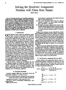
In this section, we evaluate the performance of the proposed transmitter and receiver designs in various multi-user MIMO downlink settings. The total number of subcarriers is 128, whereas the number of subcarriers with data symbols is 72. The subcarrier spacing is set to 15 kHz, and the bandwidth is 1.4 MHz. The data symbols are drawn from the 16 QAM constellation. We employ the WINNER Phase II spatial channel model based on the 3GPP as in [14]. The maximum channel impulse response length is approximately Lch = 22 samples. For all examples, 1000 channel realizations have been performed with 1000 symbols per subcarrier, and a single spatial stream is sent to each user. Fig. 1 depicts the BER performances of the MMSE based iterative design and the closed-form SLR based design. The former slightly outperforms the latter with the price of a higher computational complexity due to the iterative procedure. Still, the average number of iterations required for convergence is only around three. It is also worth noting that via numerical simulations, we have observed that this number is barely affected by the length of the precoders or the MIMO settings. On the other hand, even with only a single tap, i.e., B = 1, the performance superiority of the both proposed schemes over the BD based technique [8] is significant. 0
10
{z
}
−1
−2
10
−3
10
iterative design, B = 9, α = 0.01 iterative design, B = 5, α = 0.01 iterative design, B = 1, α = 0.01 iterative design, B = 5, α = 0.1 IIM−CBF 1 [12] BD based [8] −10
−5
0 E /N [dB] b
8 × 4, B = 1, iterative 8 × 4, B = 3, iterative 8 × 4, B = 1, SLR based 8 × 4, B = 3, SLR based 8 × 4, BD based [8] 4 × 4, B = 1, iterative 4 × 4, B = 1, SLR based 4 × 4, BD based [8] −5
0 Eb/N0
(24) ·ξkj
10
−15 −2
!
0
−5
−10
·
(int),j,r Ψk,k
10
10
10
−15
+
(int),j,rT Ψk,k
value for the matrix inversion regularization factor leads to a better performance in the low signal-to-noise-ratio (SNR) regime, while there is an error floor in the high SNR regime. The reason is that a larger value for the regularization factor results in larger residual ISI and residual leakage due to approximation errors induced by the regularization procedure. Unlike the low SNR regime, in the high SNR regime the residual interference (residual ISI and leakage) dominates instead of the noise. Hence, this observation inspires the design of an SNR-related regularization factor as future work. For all the values of the lengths of the precoders and the choices of the regularization factor considered in this example, the iterative scheme achieves a much better performance compared to the IIM-CBF 1 scheme in [12] and the BD based technique [8].
−4
−1
−4
·
X r=1
10
10
10
NRj
Ψs,r k,k
C
5. SIMULATION RESULTS
10
·ξkj
s=1,s6=j r=1
s=1 r=1 ℓ=k−1,ℓ6=k
uncoded BER
T ξkj
−3
{
r=1
SLRjk =
uncoded BER
}|
5
10
15
0
Fig. 2. BER performance in a multi-user MIMO downlink setting where U = 2, NR1 = NR2 = 3, NT = 6 6. CONCLUSIONS
5
10
15
Fig. 1. BER performance in different multi-user MIMO downlink settings where U = 2, NR1 = NR2 = 2, NT = 8, or 4, and α = 0.025 Via Fig. 2, the impact of the number of taps and the choice of the regularization factor is investigated. Longer precoders contribute to a superior capability in mitigating the MUI, ICI, and ISI. Hence, the BER performance of the proposed iterative approach becomes better, as the length of the precoding filters increases. Nevertheless, by increasing the length from five to nine, the performance improvement is already very small. In addition, it is observed that a larger
2432
In this work we have proposed two designs of precoders and equalizers for FBMC/OQAM based multi-user MIMO downlink systems. The first one is an iterative approach where the MMSE based precoders and the MRC based receive spatial filters are jointly computed. In the second scheme, we have devised closed-form SLR based precoders for the base station and a similar MRC based receive processing for each user terminal. Both schemes are developed to effectively mitigate the MUI, ISI, and ICI in critical highly frequency selective propagation conditions. From the numerical results it can be concluded that the first approach provides a slightly better performance compared to the second method, at the cost of a higher complexity due to the joint transceiver design. Moreover, both approaches show a considerable improvement over two state-of-the-art schemes that do not consider the channel frequency selectivity inside each subcarrier.
7. REFERENCES [1] P. Siohan, C. Siclet, and N. Lacaille, “Analysis and design of OFDM/OQAM systems based on filterbank theory,” IEEE Transactions on Signal Processing, vol. 50, no. 5, pp. 1170 – 1183, May 2002. [2] M. G. Bellanger, “Specification and design of a prototype filter for filter bank based multicarrier transmission,” in Proc. IEEE Int. Conf. Acoustics, Speech, and Signal Processing, May 2001. [3] T. Fusco, A. Petrella, and M. Tanda, “Sensitivity of multi-user filter-bank multicarrier systems to synchronization errors,” in Proc. ISCCSP, Mar. 2008. [4] H. Saeedi-Sourck, Y. Wu, J. W. M. Bergmans, S. Sadri, and B. Farhang-Boroujeny, “Complexity and performance comparison of filter bank multicarrier and OFDM in uplink of multicarrier multiple access networks,” IEEE Transactions on Signal Processing, vol. 59, no. 4, pp. 1907–1912, Apr. 2011. [5] M. Shaat and F. Bader, “Computationally efficient power allocation algorithm in multicarrier-based cognitive radio networks: OFDM and FBMC systems,” EURASIP Journal on Advances in Signal Processing, vol. 2010, Mar. 2010. [6] M. Renfors, F. Bader, L. Baltar, D. Le Ruyet, D. Roviras, P. Mege, and M. Haardt, “On the use of filter bank based multicarrier modulation for professional mobile radio,” in Proc. 77th IEEE Vehicular Technology Conf. (VTC 2013 Spring), June 2013. [7] M. Caus and A. I. Perez-Neira, “SDMA for filterbank with Tomlinson Harashima precoding,” in Proc. ICC 2013, June 2013. [8] M. Caus, A. I. Perez-Neira, and M. Moretti, “SDMA for FBMC with block diagonalization,” in Proc. SPAWC 2013, June 2013. [9] Q. H. Spencer, A. L. Swindlehurst, and M. Haardt, “Zeroforcing methods for downlink spatial multiplexing in multiuser MIMO channels,” IEEE Trans. Signal Process., vol. 52, no. 2, pp. 461–471, Feb. 2004. [10] M. Caus and A. I. Perez-Neira, “Multi-stream transmission in MIMO-FBMC systems,” in Proc. ICASSP 2013, May 2013. [11] Y. Cheng, P. Li, and M. Haardt, “Coordinated beamforming in MIMO FBMC/OQAM systems,” in Proc. IEEE Int. Conference on Acoustics, Speech, and Signal Processing (ICASSP), May 2014. [12] Y. Cheng, P. Li, and M. Haardt, “Intrinsic interference mitigating coordinated beamforming for the FBMC/OQAM based downlink,” EURASIP Journal on Advances in Signal Processing, May 2014. [13] F. Horlin, J. Fickers, T. Deleu, and J. Louveaux, “Interferencefree SDMA for FBMC-OQAM,” EURASIP Journal on Advances in Signal Processing, vol. 46, Mar. 2013. [14] M. Newinger, L. G. Baltar, A. L. Swindlehurst, and J. A. Nossek, “MISO Broadcasting FBMC System for Highly Frequency Selective Channels,” in Proc. International ITG Workshop on Smart Antennas (WSA 2014), Mar. 2014. [15] L. G. Baltar, M. Newinger, and J. A. Nossek, “Structured subchannel impulse response estimation for Filter Bank based Multicarrier systems,” in Proc. ISWCS 2012, Aug. 2012.
2433
[16] M. Sadek, A. Tarighat, and A. Sayed, “A Leakage-Based Precoding Scheme for Downlink Multi-User MIMO Channels,” IEEE Trans. Wireless Commun., vol. 6, no. 5, pp. 1711 – 1721, May 2007.