1
Preliminary Design of an Autonomous Microrobot Propelled by Magnetotactic Bacteria Walder André and Sylvain Martel NanoRobotics Laboratory, Department of Computer Engineering and Institute of Biomedical Engineering, École Polytechnique de Montréal (EPM), Campus of the Université de Montréal, Montréal (Québec) Canada E-mail:
[email protected] URL: www.nano.polymtl.ca
Abstract — The preliminary design of a fully autonomous bacterial microrobot for future operation in aqueous medium is briefly presented. The expected overall dimension of this microrobot is 650 µm × 550 µm. Prior to minimize the energy requirement collected through embedded photovoltaic cells, the motility of MC-1 magnetotactic bacteria is controlled and exploited for the displacement of the robot. This paper describes the general architecture of such microrobot with emphasis on the embedded controlled bacterial actuation in which is integrated a 3D coil solenoid based on standard CMOS technology for magnetic field generation prior to orient the swimming direction of the bacteria to propel the microrobot.
Index Terms— Microrobot, bacteria, 3D solenoid coils, photovoltaic cells
E
I. INTRODUCTION
MBEDDING bacteria in untethered microrobots designed to operate in an aqueous medium offers a compact and very effective biological micro-actuator where issues such as power source and power conversion can be eliminated or at least minimized, leading to further miniaturization. The use and integration of bacteria has been done previously [1] without directional control of the bacteria. Instead of using chemotaxis-based bacteria, magnetotaxis [2, 3] inherent in Magnetotactic Bacteria (MTB) [4, 5] allows directional control of the swimming path of the bacteria from electronics/software modules. The propulsion of the bacterial microrobot consists in exploiting the thrust of the molecular motor of the MTB with the property of the chain of magnetic single domain nanoparticles (50-100 nm in size) called magnetosomes embedded in each MTB to provide very effective autonomous motions. More specifically, a torque is induced on the chain of magnetosomes to re-orient the bacteria with small electrical currents provided by photovoltaic cells and circulating through conductor network embedded in the microrobot to achieve controlled navigation. II. GLOBAL ARHITECTURE OF THE MICROROBOT
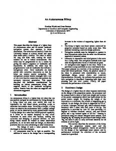
The proposed autonomous microrobot is a microsystem built with silicon MEMS using standard CMOS process, electronics and bacteria. This microrobot consists of a die containing micro-reservoirs that shelter magnetotactic bacteria to form a bacterial propulsion system. Inside each microreservoir, there is a coil. With the flow of an electrical current along the conductive coil, a magnetic field likely to orient the bacteria is generated. Through magnetotaxis, their swimming directions can be changed towards a wall of the microreservoir towards which point the magnetic field lines emanating from the inside of the solenoid coil is used to create a controlled pushing or propelling force on the microrobot from an agglomeration of MTB. A first version of the architecture of the microrobot is depicted in Fig. 1. Inside each microrobot, a preprogrammed microchip is used to embed a specific behavior. In this configuration of the microrobot, the horizontal set of microreservoirs serves as rudder while the vertical sets of microreservoirs are to perform forward or backward movement.
Coil
MTB
Fig. 1. Schematic (not to scale) of the architecture of the microrobot. This picture shows 4 photovoltaic cells that drive the embedded electronics used to control the swimming direction of the MTB. The vertical set of microreservoirs is intended for forward movement while the horizontal set of microreservoirs emulates a rudder.
This architecture uses the minimum quantity of electronic components necessary to preprogram a specific task or behavior. For such a microrobot, CMOS photovoltaic cell is a suitable solution to provide minimum electrical power for the
2 embedded electronics used to control the motion of the bacteria. Today’s technologies allow complete integration of micromechanical structures with CMOS microchips [6]. This is possible through deposition and etching of sacrificial layers such as silicon dioxide (SiO2) in order to obtain the 3D structures of the micromechanical devices. Several techniques have been reported in order to remove the silicon dioxide sacrificial layer such as HF, BHF, R-etch, and S-etch. Unfortunately, the above-mentioned etchants attack severely the aluminum up to a rate of 2000 Å after 5 minutes [7]. However, the etchant called Pad-etch and considered here to release the 3D structure of the CMOS coil increases the maximum surface roughness of the aluminum and serves as a shield that protects the aluminum against further action of the etchant [7]. Using the standard CMOS process, the bacterial reservoirs and the power system (the photovoltaic cells) can be embedded onto the microrobot [8]. The area of such a microrobot is presently estimated at 650 µm × 550 µm. It consists of a silicon die that integrates bacterial reservoirs for actuation, four photovoltaic cells for power, and an embedded electronic circuit. The photovoltaic cells are designed to provide 100 µA necessary for directional control of the embedded MTB. Such electrical current flows inside the coils to provide a local minimum magnetic field of approximately 0.5 Gauss necessary for influencing the trajectory of the bacteria. In order to provoke a forward or a backward movement, the quantity of bacteria per reservoir necessary to overcome the drag force that acts on the microrobot has to be evaluated. The same architecture of the microrobot but designed for simulation and fabrication with Cadence Layout Virtuoso tools is depicted in Fig. 3.
PV cells
Bacterial reservoirs
FB = γ × V ,
(1)
where FB is the buoyancy force, γ is the specific weight of the liquid and V is the volume of the submerged body. Therefore, the buoyancy force is found to be 0.9×10⁻⁶ N. Here the buoyancy force is less than the weight of the microrobot. From previous experiences, we demonstrated that a single MC-1 bacterium was able to produce an average thrust of 4 pN and push a 3 µm diameter bead with an average velocity of 128 µm s-1 [14]. Based on this preliminary result and according to the form factor on the microrobot, an average number of 100 MTB should be sufficient to propel the microrobot with an average speed of ~14 µm s-1. The drag force acting on the microrobot is evaluated from the corresponding Reynolds number, which is given by ρvd , Re = (2) η where Re is the Reynolds number, ρ = 1000 kg/m3 is the fluid density, we assume the worse case microrobot speed relative to the medium of ν ≈ 14 µm/s, η is the dynamic viscosity of the medium, which is 1.003 × 10⁻⁴ kg/ms at 20 ºC, and d = 550 µm is the characteristic length of the microrobot in the direction of the flow. The low Reynolds number of 7.7 × 10⁻² < 1 indicates that viscous forces dominate, and that the Stokes law can be used to calculate the drag force. For a sphere, it is given by:
FD = 6πη × rν
(3)
where FD is the drag force, r is the width of the surface moving against the liquid. An approximated drag force of 0.145 × 10⁻⁹ N is obtained. Fig. 4 shows the internal architecture of the microrobot with the control logics consisting of a simple state machine capable of controlling the flow of the current through selected conductors for directional control of the MTBs.
Control logic device Bacterial reservoirs
Photocells
Fig. 3. Schematic (not to scale) of the architecture of the microrobot designed in Cadence layout Virtuoso, showing the microreservoirs, and the photovoltaic cells.
First, an evaluation of the weight of the microrobot is given. Knowing that the specific weight of a CMOS die is ~11 µN/mm2 and 5 µN/mm2 for a die thickness using 550 µm and 250 µm technologies [9], the weight of the microrobot can be estimated at 1.6 µN. The evaluation of the buoyancy force is given by
Clock generator Fig.4. Block diagram of the internal embedded electronics of the microrobot.
3
Fig. 5. (a). Simulated results showing current versus frequency response of the coil solenoid when driven by a 1 VAC supply. (b) Simulated results showing voltage versus frequency response of the coil solenoid when driven by a 1 VAC supply. (c). Simulation results for the ratio of the AC resistance over DC resistance. It shows the effect of the increase of the frequency on the AC resistance. (d) Matlab simulation results showing the distribution of the magnetic field inside the coil along the x-y coordinates (see Fig. 9).
III. FABRICATION OF THE BACTERIAL RESERVOIR The bacterial reservoir is a MEMS structure based on standard CMOS process. Originally, MEMS based components which were intended to be driven by electronic circuits such as standard CMOS microelectronic chips were designed separately, increasing significantly the complexity of their integration while increasing capacitance through coupling on a single chip that is more likely to affect performance. Although such capacitance can be estimated through lumped macro models and then compensated for in the design process but would yield larger implementations which is not suitable here. To reduce the complexity in the fabrication of the bacterial reservoir, a 3D square hollow coil in standard CMOS process is developed [10]. It is designed such that the distance between coils turns is less than the diameter of a bacterium in order to prevent bacteria from escaping. To design the 3D coil, some computations have been carried out to obtain its physical characteristics. These bacterial reservoirs are designed to be integrated on the same chip as the electronic circuits that drive them. The 3D square coil has winding dimensions of 6µm ×
6µm with a depth of 10 µm as depicted in Figures 6 and 9. 3-D square solenoid MTB Reservoir
Fig. 6. Schematic (not to scale) of the bacterial reservoir inside which is embedded a 3D solenoid coil.
The coil is fabricated with the same standard CMOS 0.18 µm using six metal layers as shown in Fig. 7.
4 M6
l1
VIA
M5
VIA
M4
i
(1)
VIA
M3
(2) i
i
VIA
M2
r
ω
VIA
(5)
l2
(3) i
i (4) d
M1
l1
Fig. 7. Cross-sectional view of the different layers used in the design of the bacterial reservoir.
Fig.8. Schematic of a one loop square coil with square wires
The equation to obtain the self inductance for a N loops rectangular coil made of a rectangular wire is given by [11], where µc is the core permeability; l1, l2, and w are respectively the length, the height of the single rectangular loop and the thickness of the wire (see Fig. 8). A self inductance of 2.16 nH is calculated from Eq. 4. N µc 2l 2 2l −1 l + 4l1 ln 1 − 4l 2 sinh 2 4l2 ln 4π w w l1 l 1/ 2 − 4l1 sinh −1 1 + 8 l12 + l 22 l 2 + 2(l1 + l 2 ) × (− 2 ln 2 − 1.004) ]
(
)
+
Nµ c i 4π (l − y )
+
Nµ c i 4π (l − x )
+
Nµ c i 4πy
l−y
(l − y )2 + l 2
+
Y
(l − x )2 + (l − y )2 l−y
(l − x )
2
l−x
(l − x )2 + l 2
+ (l − y ) +
2
+
(l − y )2
+ x 2
(l − x )2 + y 2
x 2 + y 2 x
Matlab software was used to evaluate the internal magnetic field distribution of the micro-coil depicted in Fig. 5d. From this curve we can observe where the magnetic field intensity is stronger than the minimum required of 0.5 Gauss. The figure also shows that the magnetic field is greater at the corners of the micro-coil while it decreases as we move toward the center. The lumped model (Fig. 10) for the inductor is based on the CMOS 0.18µm process data.
Ls
Rsub
x
+
Fig. 9. Schematic showing the bacteria swimming along the magnetic field inside the coil. The (x, y, z) axis allows us to determine the exact magnetic field acting on the bacteria according to its position as in Eq. 7.
Cox
y 2 2 x + y
l−x
y
Z
B
(4)
The expression of the magnetic field for the rectangular coil located at a point p(x, y) when coil segments of length l are driven by a current is given in Eq. 5 [12]. According to Eq. 5 with the proposed 3D square coil, a magnetic field of 0.6 Gauss can be achieved near the center of the coil with a current of 100 µA. This intensity is greater then the earth’s magnetic field and from data obtained in past experiments, it should be sufficient to orient the MTB to push against the reservoir wall, resulting in a displacement of the microrobot. It should be noted that at such low magnetic field, the environmental conditions must be controlled since the effects of chemotaxis and aerotaxis would be more significant. Very good responses in re-orienting the MTB have been observed by our group when applying larger magnitudes of approximately 3 Gauss. Nµ c i B= 4πx
MTB
I
2
L≈
X
Csub
Cs
Rs Cox
Rsub
Csub
Fig. 10. Schematic of the П lumped-model of the CMOS inductor.
(5) In Fig. 10, Cs is the series capacitance, Rs is the metal series resistance, Rsub is the series resistance due to substrate loss, Csub is the capacitance per unit area between the inductor coil and the substrate, Cox is a parasitic capacitance and Ls is the coil inductance. With the use of Cadence schematic tool, the lumped model for the inductor is then simulated with the appropriate physical data obtained from the foundry. A first
5 simulation is done to determine the frequency dependence of the coil resistance for its characterization. The values of the sheet resistance of the six metals that intervene in the design of the 3D CMOS coils are for CMOS 0.18 µm technology: metals 1, 2 and 3 it is ~0.08 Ω/square, for metals 4 and 5 the sheet resistance it is 0.07 Ω/square, and finally for metal 6 the sheet resistance is 0.01 Ω/square [13]. This data obtained are helpful to determine the loss due to the substrate. Fig. 5a and 5b present the AC response of the coil obtained form Cadence schematic tool with an alternating voltage of 1 V applied at the input of the CMOS coil. A decrease in voltage across the coil is shown in Fig. 5b. In addition, Fig. 5c shows that the ratio AC to DC resistance increases with an increase of the frequency. This is due to the fact that AC resistance, which is the inductive reactance of the coil, increases with frequency because of skin effect. At high frequencies, the self inductance of the coil increases the inductive reactance of the coil, which retrains the flow of the current in the very small area of the cross-section of the conductor, thus opposing the flow of the current. This explained the increase of the AC resistance of the coil above a certain frequency. In our application, this 3D CMOS coil, embedded in the micro-reservoir presented in Fig. 9 will be connected to the photovoltaic cells (DC output). The process for a micromachined DC coil is the same as for an AC coil. Due to the absence of inductive reactance when the coil is connected to a DC supply, there is more current flowing into a DC coil than into an AC coil. According to Biot-Savart law, the magnetic field generated by a DC coil will be stronger. IV. BACTERIAL INTEGRATION The method considered to encapsulate the MTB in the micro-reservoirs is based on the application of a magnetic field inside the micro-coils embedded in each micro-reservoir. This will be done while the microrobot is submerged in an aqueous medium containing thousands of MTB. MTB will be attracted by the magnetic field generated inside the microcoils and trapped into it while maintaining their swimming orientation towards the bacterial reservoir wall (Fig.11). The resulted bacterial propulsion system is depicted in Fig. 12. Thrust Drag
Bacterial reservoir Microcoils
MTB
SI
Fig .12. Cross-sectional view of the microrobot showing the integration of the MTB into the micro-reservoir.
V. FABRICATION OF THE PHOTOVOLTAIC CELLS The microrobot will be powered through integrated photovoltaic cells. These are designed to provide a DC current of 100 µA through the conductor coil. The architecture of one photovoltaic cell is obtained by alternating the n and p-type semiconductor at any given part of the area of the photocells to increase the active area for photo current conversion [8]. Therefore, with a smaller area, one can achieve the highest output current possible. Figs. 14 and 16 show the Spice simulation results of the photocells [8].
Iph (µA)
100 80 60 40 20 0
Fig. 11 shows the action of the bacteria on the reservoir wall to form a propulsion system.
0.1
0.2
0.3
0.4
0.5
0.6
Voc (V) Fig. 14. I-V characteristic of the photovoltaic cell under 100µW/cm2 light intensity.
6 [4]
Pph (µW)
[5]
100
[6]
80
[7]
60 [8]
40 20 0
[9]
0.1
0.2
0.3
0.4
0.5
0.6
[10]
Voc (V) Fig. 15. P-V characteristic of the photovoltaic cell under 100µW/cm2 light intensity.
V. CONCLUSION A fully autonomous bacterial microrobot for future operations in an aqueous medium is presented. The final goal is to create a fleet of interacting microrobots with preprogrammed behaviors for operations in a fluid sample. Because of their motility, magnetotactic bacteria are used to propel the microrobot. For the untethered microrobot, photovoltaic cells have been used as power systems for the embedded electronics. A minimum current of 100 µA is estimated to drive the conductor in order to provide the minimum required magnetic field necessary to orient the swimming direction of the bacteria. Finally, a special technique for building the bacterial reservoirs on standard CMOS process and based on a 3D rectangular coils are presented. We have computed a value of 2.16 nH according to the size of the coil. Simulations have been done with Cadence layout Virtuoso and schematics with lumped-models of the coil. ACKNOWLEDGMENT This work was initially fully supported by a grant from the Canadian Institute for Robotics and Intelligent Systems (IRIS). The project is supported in part by the Canada Research Chair (CRC) in Micro/Nanosystem Development, Fabrication, and Validation, the Canada Foundation for Innovation (CFI), the National Sciences and Engineering Council of Canada (NSERC). REFERENCES [1] [2] [3]
N. Darnton, L. Turner, K. Breuer, and H. C. Berg, “Moving fluid with bacterial carpet,” Biophysical J., vol. 86, pp. 1863-1870, 2004. R. B. Frankel and R. P. Blakemore, “Navigational compass in magnetic bacteria,” J. of Magn. and Magn. Materials, vol. 15-18 (Part 3), pp. 1562-1564, 1980. H. Debarros, D. M. S. Esquivel, and M. Farina, “Magnetotaxis,” Sci. Progr., vol. 74, pp. 347-359, 1990.
[11] [12]
[13] [14]
R. P. Blackmore, “Magnetotactic bacteria,” Science, vol. 190, pp. 377379, 1975. R. P. Blakemore, “Magnetotactic bacteria,” Annu. Rev. Microbiol., vol. 36, pp. 217-238, 1982. Harrie A. C. Tilmans, Kris Baert, Agnes Verbist, and Robert Puerts, “CMOS foundry-based micromachining,” Journals of Micromech. Microeng. vol. 6, pp. 122-127, 1996. Buhler L., Steiner F-P, and Baltes H., “Silicon dioxide sacrificial layer etching in surface micromachining,” Journal of Micromechanics and Microengineering, vol. 7, no. 1, p R1-13, March 1997. W. Andre and S. Martel, “Design of photovoltaic cells to power control electronics embedded in untethered aqueous microrobots propelled by bacteria,” Int. Conf. On Intelligents Robots and Systems (IROS), Beijing, China, October 9-15, pp. 1335-1340, 2006. J. W. Suh, R. B. Darling, K. F. Bohringer, B. R Donald and H. Baltes, “CMOS integrated organic ciliary actuator arrays for general-purpose micromanipulation tasks”, Distributed manipulation, p 191-215, 2000. Y-K Yoon, Emery Chen, Mark G. Allen, and Joy Laskar, “Embedded Solenoid Inductors for RF CMOS Power Amplifiers,” TRANSDUCERS '01. EUROSENSORS XV. 11th International Conference on Solid-State Sensors and Actuators. Digest of Technical Papers, pt. 2, vol.2, pp. 1114-1117, 2001 M A. Bueno and A. K. T. Assis, “ A new method for inductance calculations,” J. Phys. D: Appl. Phys. 28, p 1802-1806, 1995. A. O Rodriguez, R. Amador, R. Rojas, and F. A. Barrios, “ Magnetic field visualization and impedance calculation of a sample configuration surface coil at low magnetic field,” Journal of REVISTA MEXICANA DE FISICA E 52 (1) 1-12 June 2006. http://www.mosis.org/products/fab/vendors/tsmc/tsmc018/ S. Martel, C. C. Tremblay, S. Ngaken, and G. Langlois, “Controlled manipulation and actuation of micro-objects with magnetotactic bacteria,” Appl. Phys. Lett. vol. 89, no. 23, pp233904, 2006