Explores the variable names of the VID. Set_var_link .... is, for example, URIs based systems could require DNS (Domain Name Server) services, which are not ...
Process data abstraction/accessibility via internet Manel Velasco, Pau Marti and Josep M. Fuertes Automatic Control & Computer engineering Department Technical University of Catalonia Pau Gargallo 5, 08028 Barcelona, Spain {mvelasco,pmarti,pepf}@esaii.upc.es
Abstract The increasing use of internet in the automation field has brought new challenges in the remote control, supervision and management of industrial processes. Specifically, process data information has to be available anywhere/anytime on the internet. This brings together two main problems: process data abstraction and process data accessibility. In this paper, we present a specification for an environment aimed to virtually model industrial plants, for their remote control, supervision and management. In this environment, we model real industrial plants by means of communication objects called virtual industrial devices (VID). A VID is a software component, which may contain other VIDs and represents, with different degrees of abstraction, an entity of an industrial plant. These objects communicate and are accessible through a peer-to-peer industrial communication protocol that allows messaging interchange between virtual industrial devices (and graphic user interfaces) regardless the communication technology that supports the actual messaging.
1.-Introduction Two strong tendencies are presently characterizing the industrial automation field: the increasing utilization of flexible and powerful networked control systems (NCS) and the
expanding role of Internet as communication backbone. NCSs provide known benefits for industrial manufacturing processes such as modular and flexible system design (e.g. distributed processing and interoperability), simple and fast implementation (e.g., small volume of wiring and powerful configuration tools), and powerful system diagnosis and maintenance utilities (e.g., alarm handling and supervisory packets) [SCO00]. On the other hand, Internet and the World Wide Web permits to interact remote computers easily, thus providing simple mechanisms for information exchange [WEA97]. The main goal of this paper is to adequately integrate these two tendencies to build worldwide distributed software architecture, based on an object model named VIEW (Virtual Industrial Environment Watcher), that allows us to virtually model real industrial manufacturing processes for their remote control, supervision and management. To accomplish with our objective, we address two main issues: process data abstraction and process data accessibility. Process data abstraction is achieved by means of a specification for a software architecture composed by communication objects called virtual industrial devices (VID). A VID is a software component that represents, with different degrees of abstraction, an entity of an industrial plant. By structuring ensembles of virtual industrial devices we are able to model any real industrial manufacturing process, with independence of its physical realization. Process data accessibility is achieved by a high-level peer-to-peer industrial communication protocol called virtual industrial protocol, VIP. VIP allows messaging interchange between virtual industrial devices (and graphic user interfaces) regardless the communication technology that supports the actual messaging.
The rest of this paper is structured as follows. Section 2 remarks the motivation of the work we present and outlines the major problems we faced. Section 3 introduces the environment specification that allows to abstractly model real industrial processes [MAR99] [MAR00] by means of virtual industrial devices. Section 4 presents the peerto-peer communication protocol that enables messaging and interaction between virtual industrial devices [VEL02]. Finally, Section 5 draws the conclusions and points out some directions for future research.
2.-Objectives and problem formulation VIEW (the distributed object environment aimed to abstractly model - for remotely control, supervision and management - industrial manufacturing processes over crossnetworking technologies) seeks to find a global solution that brings together the abovementioned main tendencies in industrial automation, that is, the integration of Networked Control Systems and Internet. The feasibility of such solution requires making visible and available process data information, regardless the specific manufacturer software and communication technologies that underlie the whole environment. Our first goal, it to set industrial plants free from their physical reality, components and relationships among them, by means of structured ensembles of virtual industrial devices. That way, an abstract representation will be created, making thus possible the remote control, supervision and management of any piece of industrial equipment, with independence of the manufacturer software abstractions that the target NCS software may already provide. It is well known that many commercial Networked Control Systems for process automation employ proprietary (or even) open software products
and specifications that offer different type of abstractions of industrial devices, e.g., MAP Virtual Manufacturing Devices [VAL92], Fieldbus Foundation Functional Blocs [FF99] or Profibus Virtual Fieldbus Devices [SEM02]. However, such abstractions usually are technology and engineering oriented, precluding thus their direct connectivity. That is, a Profibus VFD cannot directly communicate with a FFB because their object message services are not the same. Therefore, to overcome this lack of connectivity, we specify a metamodel architecture that allows their connectivity, and thus their accessibility in a cross-platform objected-oriented modeling and communication environment. Our second goal is to make those virtual industrial devices worldwide accessible by means of browsers, i.e., user graphic interfaces, with independence of the relying communication technology. It is also well known that in the automation field there is a lack of methodologies for the integration of fieldbus standards. Our environment must be effective over a great variety of networking technologies, which may include both de-facto standard control networks [SCO00] (such as Controller Area Network [CAN93] or Profibus [SEM02]) and office automation networks (such as TCP/IP based networks [STE94]). Notice that well known middleware communication architectures (see [KAN01] for a short review) such as Common Object Request Broker Architecture (CORBA [OMG98]) or Java Remote Method Invocation (RMI [RMI98]), that require TCP/IP based networks, are not suitable for our environment, because we want to guarantee communication between objects (virtual industrial devices) implemented on top of different processing platforms, such as a CAN node or a standard PC (personal computer).
To overcome this problem, we present a high-level peer-to-peer communication protocol, called virtual industrial protocol (VIP), based on the Simple Object Access Protocol (SOAP)[SOA01], which allows communication between VID, with independence of the communication networks, operating systems and languages that may be involved in any transaction. The VIP incorporates a new routing service (Industrial Routing Protocol, IRP) that routes VIP messages to any VID.
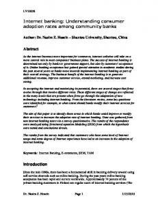
3.-Virtual industrial devices In this section, we describe the VIEW object model that specifies the modelling of industrial plants by means of virtual industrial devices (VID). Figure 1 illustrates this concept.
VID
VID VID
VID VID VID
VID VID
Structured ensemble of VIDs
VID
Intenet Profibus CAN
VID
Real industrial process
Figure 1. VIEW object model
3.1.- Functional requirements In an early stage of the VIEW development, the first question was to determine how any industrial plant could be abstractedly modeled by software components. That led us to define a light object-oriented model based on communication objects called virtual
industrial devices. Light refers to the fact that structured ensembles of simple communication objects should be able to represent any real industrial plant, any of its components and any inner relationship among them. In other words, generality was needed. To do so, a simple communication object specification has been defined, which allows the modeling of industrial plant components following objected-oriented methodologies. The object model used for VID assures their intercommunication just by invoking their methods.
3.2.- Structure Virtual industrial devices are communication objects characterized by logical access points, variables and methods. VID logical access point is used for routing purposes. VID variables represent the VID state. VID methods specify the actions performed by/on VID. Actions are mainly structural or supervisory. Structural actions allow two main functionalities: •
configuring and linking variables of different VIDs (Set_var_link)
•
browsing the ensemble of VIDs (Get_var_names, Get_VID_connections and Get_VID_id)
Notice that links between variables of different VIDs corresponds to the required path between VIDs used in the routing mechanisms. Supervisory actions main purpose is to facilitate operation with VID contents, that is, with its variables. By means of these VIDs, we generate a distributed software architecture, which, by grouping VIDs in graph structures, allows us to represent real any real industrial process. The specified actions can be seen in table 1.
Type of action Structural
Supervisory
Action Get_var_names Set_var_link Get_VID_connections Get_VID_id Set_var_value Get_var_value
Explanation Explores the variable names of the VID Links two variables of two VIDs Obtains the logical connections of a VID Obtains the logical VID’s identification Writes the value of a VID variable Reads the value of a VID variable
Table 1. List of specified actions
Virtual industrial devices can be configured in order to interact with physical devices by means of accessing libraries. Using these libraries, VIDs variables are kept up to date in relation to the state of the physical entity they represent. Therefore, accessing these VID variables is like accessing real process variables. Looking at the virtual plant structure, VID that are attached to real plant devices are usually at the end of the tree previously mentioned structures. In this sense, we distinguish two type of VID: terminal VID, which interact with the real plant; and structural VID, which represent (logical) groupings of other VID (either terminal or structural). Virtual plant communication services (VIDs public methods) let remote both configuration and access to real plant data that is encapsulated in virtual industrial devices. Data accessing is done by means of browsers, i.e., graphic user interfaces, that translate user commands into messages, and messages are appropriately routed and translated into actions on virtual industrial devices. This messaging mechanism also allows VID to obtain data from an industrial process that occurs remotely and to use it locally, or to perform actions on a remote process as a function of local parameters.
3.3.- Example In this section, we show using an example of the VIEW object model applied to a simple industrial process: we monitor the error of a PID speed control of a DC engine.
The closed-loop system has been implemented on a CAN network that has 1) PWM actuator node, 2) speed sensor node, 3) a PID (Proportional, Integrative and Derivative) controller node and 4) a PC for network management. Let us suppose that on each CAN node we have a VID that virtually models the real device. The Actuator_VID has a single variable named PWM_value. The Sensor_VID has a single variable named Speed_value. The PID_VID has seven variables (Kp, Ki, Kd, Err, Control_signal, Controlled_variable and Reference_signal), which models the real PID node. Finally, the PC_VID has four variables, which represent the PID node inputs (PC_Kp, PC_Ki, PC_Kd and PC_Reference_Signal), which are used to tune and alter the PID behaviour. The logical links between these four VIDs variables are expressed with dotted arrows in the Initial set of Figure 2, which also illustrates the whole set-up explained next. Initial Set
VID
VID
VID Variables
Variables
Variables
PC_Kp PC_Kd PC_Ki PC_Reference_Signal PWM_value Err
VID
VID
Variables
Variables
Kp Kd Ki Reference_Signal Controlled_variable Control_signal Err
VID and variable link layer Speed_value Logical connection layer
Remote PC
Internet
PC
CAN Node
CAN Node
CAN Node
CAN Bus Bus layer Actuator
PID
Sensor
Reality layer
Figure 2. Real and virtual manufacturing process
These logical links between variables have been settled in the virtual environment setup by combining Get_VID_connections, Get_VID_id and Set_var_link functions. On this initial set-up, a user wants to monitor the PID error variable from an external device connected to Internet. To do so, the user uses the Set_var_link function to relate the err variable of the PID_VID to its own Monitor_VID variable. Therefore, each time the err variable value changes the Monitor_VID will get the update.
4.-Virtual industrial protocol In this section, we present the main features of the specification of the virtual industrial protocol (VIP), which includes a new industrial routing protocol (IRP). The main features of the VIP is to grant access to worldwide process data that is encapsulated in VIDs, which are implemented on top of physically distributed processing nodes that may belong to different networking technologies.
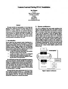
4.1.- Description The object model that structures virtual industrial devices requires a communication scheme able to guarantee messaging with independence of the networking technologies that actually underlie the virtual environment. To do so, we have provided our virtual object model with a specification of new high-level peer-to-peer communication protocol that enabling the SOAP with a new routing service allows communication between virtual industrial devices regardless the communication technology that supports the actual messaging. This is illustrated in Figure 3.
Figure 3. Messaging scheme
SOAP (version 1.2) provides a simple and lightweight mechanism for exchanging structured and typed information between peers in a decentralized, distributed environment, using the Extensible Markup Language (XML [XML]). SOAP does not itself define any application semantics, such as a programming model or implementation specific semantics; rather it defines a simple mechanism for expressing application semantics by providing a modular packaging model and mechanisms for encoding application defined data. This allows SOAP to be used for a large variety of purposes ranging from messaging systems to remote procedure call (RPC) invocations. SOAP messages are fundamentally one-way transmissions from a SOAP sender to a SOAP receiver; however, SOAP messages are often combined to implement patterns such as request/response. SOAP does not provide a routing mechanism, however SOAP does recognize that a SOAP sender originates a SOAP message, which is sent to an ultimate SOAP receiver, via zero or more SOAP intermediaries.
The main idea behind the virtual industrial protocol specification is to use SOAP properties to encapsulate messages that will be transported on the data field of any relying/intermediate protocol. A VIP message formatted under SOAP will be segmented and reconstructed using any number of segments at each VID.
Figure 4. Message Segmentation
Therefore, as we show in Figure 4, each virtual industrial device will be in charge of 1) segmenting the VIP message in order to insert it into the specific communication protocol frame(s) that will transport it, and 2) reconstructing the segments and interpret its structure and contents (in the destination device). Depending on weather the receiving VID is the VIP message destination, two main procedures may occur: •
if the VID is the destination node, after the message reconstruction, it will interpret the message and take the corresponding actions, which may imply interfacing the real device via the driver services.
•
if the message is addressed to another VID, the message will be appropriately forwarded. If the routing implies to shift network protocol, the routing service will be in charge of reconstructing and segmenting the message again in order to allow its transportation by the new communication network frames.
The reconstruction rules for obtaining the original message from the incoming message depend on the type of network in which the message is transported. This implies that the receiving VID implements all necessary procedures for adequately reconstructing the incoming messages. At the end, VIP messages for industrial virtual devices are able to travel on a great variety of communication protocols.
4.2.- Message structure The compulsory elements on a SOAP based VIP message are: the header, including the routing and the message service type; and the body, including the message contents. The following scheme (Figure 5) structures these three elements. Notice that SOAP contains the real VIP message, thus acting as a simple envelope. Therefore, the IRP routing placed in the header is the envelope stamp (i.e., it specifies the destination address).
Figure 5. VIP parts inside a SOAP message.
The routing information structure is divided into two areas, one referring to the destination and the other one referring to de origin of the message. The destination gives the complete path (intermediates and final connections) for routing the message peer-topeer. The origin has been included inside of the routing for the following reason: SOAP is a stateless messaging system, i.e., no information of the connection is included within the message. This implies that at the destination node, the sender and backward connection path is not known. To overcome this problem the IRP specifies the return path in the origin area of the routing structure. Origin and destination routing structures are defined by means of two tags, and . A path is expressed by a nested chain of names and values. A tag logically expresses the connecting address. It will be used to forward or backward messages. Values are used for structuring the path in a tree-like fashion, containing either more values or names. For illustrative purposes (avoiding the XML formalism), a path could be expressed as shown in Figure 6.
Figure 6. IRP path
An empty tag means end of the path. A message reaches the destination when the message received by a node has an empty tag in the destination field.
The VIP provides three different message services, which are specified in the tag, that are summarized as follows: •
Asynchronous request without confirmation: the VID sender sends a message without having to wait for the answer. The VID receiver, after processing the petition, generates an appropriate answer (if needed) to the original petition.
•
Asynchronous request with confirmation: the VID sender sends a request and a confirmation from the VID receiver is required, regardless whether the requested petition required response or not.
•
Synchronous request: the VID sender, after sending a request, waits until it receives the answer. The reception of an acknowledge message typically implies a successful completion of the requested service.
The contents element of a VIP message placed in the body area of the SOAP message is the user data. Typically, the message body contents actions to be performed to VID, as well as, the related responses. These actions allow us to remotely control, supervise and manage industrial processes.
4.3.- Routing One of the most complicated problems that the VIP solves is the message routing. Note that the IRP we present is similar to WS-Routing [WS] that is used in web-service based communications. WS-Routing uses Universal Resource Identifiers (URI) to identity all nodes of a networked environment. A URI is simply a formatted string that identifies via name, location, or any other characteristic - a resource on the Web. The universal property of URIs requires a wide underlying communication structure (to translate URIs into specific network addresses) that may not be common in industrial scenarios. That
is, for example, URIs based systems could require DNS (Domain Name Server) services, which are not common in CAN based networks. To avoid this problem we present a local routing for SOAP messages that allows routing messages to the destination without requiring the URI translation services. That is, using the new IRP, we extend the routing capabilities over any type of network (regardless of being based on http), facilitating thus communication services between virtual industrial devices physically placed in heterogeneous networks. One of the most important features of the VIP is that a VID can only directly communicate with another VID if the later is visible. This basically means that every time a VID wants to communicate with another VID that is not a neighbor (in the sense of being physically located in its same network), the communication is achieved through the routing mechanisms. Instead of global and static routing (required for example for TCP/IP messages), the main idea of the IRP is to drive messages by means of a local routing, where the routing information is created and updated according to the system dynamics. Each time a connection is established between a pair of VIDs, the connection is logically recorded, stored and named by each VID into a list of named connections. The list of named connections can be accessed through a specific function (Get_VID_Connections, see sec. 3.2) defined in VIDs by other VIDs. This specific function can be placed in the message body of a requester VID. In this way we obtain a local routing rather than a predefined and static global routing. In short, the IRP rules are the following:
•
the sender sets in the message tag an empty tag and full path in the tag. The destination path specifies the logical names of the peerto-peer connections from the sender node to the destination node.
•
A receiver node checks if it is the final destination. Two cases may occur: if the tag is empty (i.e., it has an empty outer tag), the receiving node is the final destination, which implies to process the action specified in the message body. Otherwise, the receiving node has to forward the message, which implies a) to add in the tag the incoming backward connection logical name, b) to remove in the tag the outer logical name and c) to actually send the message to the removed logical name.
In the following section, we illustrate with detail the above listed routing mechanisms. 4.3.3 Example Let us suppose that we have four VIDs named A, B, C and D. VIDs A, B, C and D are physically connected by different communication networks, as shown in Figure 7. During the logical connection process (environment setup), each VID name each connection with a specific logical name. For example, the connection between D and C is arbitrary named as D1 by D, while C names the same connection as C1
Figure 7. Logical connections and naming for each VID connection
Lets us suppose that we want to send a message from A to D. The first thing to do is to get the path from the message origin, A, to the message destination, D. This path is B-CD (or A1-B1-C1 if we use the logical names of the connections in the path). Routing 1: A to B via connection A1
Origin
Destination
B1 C1
Routing 2: B to C via connection B1
Origin
Destination
B2
>C1
Routing 3: C to D via connection C1
Origin
Destination
C2 B2
Figure 8. Message routing from A to D
Once the sender knows the path, the following peer-to-peer transactions, which we represent in Figure 8, take place (Notice in Figure 8 that we do not specify the exact structure of the routing, rather it’s approximate scheme. However, in the message implementation, origin and destination belong to the tag of the SOAP message header): •
Knowing this path, node A sends a SOAP message through A1 connection (its own connection to B) specifying also the full remaining path B1-C1 in the destination area of the message, as we show in Figure 8 (Routing 1). Notice also that the origin area is empty because A is the sender.
•
When B receives the message checks the routing area in order to see if it is the destination node. In this case, due to the fact that the tag at the outer level of the destination is not empty (it contains B1-C1), it forwards the SOAP message according to specified rules. That is, as we show in Figure 8 (Routing 2), it sends the message through B1 connection while, first, it eliminates the reference to B1 in the destination route, and secondly, it specifies in the origin area the name of the incoming backward connection, in our case B2.
•
Once node C receives the message, it checks if it is the final destination. As we have C1 in the destination area, node C has to forward the message through C1 connection. As before, node C will also remove the reference to C1 in destination area and it will specify in the origin area the name of the incoming backward connection, in this case C2, as we show in Figure 8 (Routing 3). Notice that the message that is sent from C to D has no destination specified in the tag.
•
Therefore, when the message arrives to node D, it checks the destination and no remaining path is found, which means that node D is the final message destination (recall that the message was sent from A to D). Consequently, node D will process the message transported inside the tag of the SOAP message. To process the message may imply to perform actions on the VID as well as to reply to the message sender.
When the receiver node has to send an answer, the receiver node will send a new message to sender node exchanging the path of by and by , because the tag of the incoming message is already specifying the returning path. For example, if the receiver node D replies A, the
message answer will have the for the first peer-to-peer transaction as shown in Figure 9. Origin
Destination
C2 B2
Figure 9. Message reply path
Notice that the message reply goes now from D to A following the same routing mechanisms, which implies sending the message through the D1 connection with an empty origin tag (D is the sender) and a destination path C2-B2. Recall that the destination path names are logical names specified by each intermediate node. Therefore, when the message travels backwards, each routing node will find its own notation in the outer routing path, allowing a correct routing to the destination.
6.- Conclusions In this paper we have presented an object model specification, which includes new communication mechanisms for remote objects, that allows us to build virtual models of industrial manufacturing processes (over a cross-networked computing platform) for their remote control, supervision and management. In the specification of VIEW (Virtual Industrial Environment Watcher) we addressed two main issues: process data information abstraction and accessibility. Process data abstraction has been achieved by structured collections of virtual industrial devices, which are software components that represent with different levels of abstraction any part of a manufacturing process. Process data accessibility has been solved by a peer-to-
peer virtual industrial protocol that, including a new routing service, allows virtual industrial devices to exchange information with independence of the underlying networking technology.
References [CAN93] Controller Area Network (1993). ISO11898 Road Vehicle – Interchange of Digital Information – Controller Area Network (CAN) for High-Speed Communication, ISO. [FF97]
Fieldbus Foundation (1997-1999). FF 890-894 Foundation Specification – Function Block Application Process. Part 1 to 5. Austin, Texas
[KAN01] W. Kang, H. Kim, H.S. Park (2001) Design and performance analysis of middleware-based distributed control systems. Proceedings 8th IEEE International
Conference
on
Emerging
Technologies
and
Factory
Automation, Volume: 2 , Page(s): 253 -260 vol.2 [MAR99] P. Martí, J.C. Aguado, F. Rolando, M. Velasco, J. Colomar, J.M. Fuertes, (1999). A Java-Based Framework for distributed supervision and Control of industrial processes, Proceedings of the 7th IEEE International Conference on Emerging Technologies and Factory Automation. Barcelona, Spain [MAR00] P. Martí, J.C. Aguado, F. Rolando, M. Velasco, J. Colomar, J.M. Fuertes (2000) Distributed Supervision and Control of Fieldbus-Based Industrial Processes, Proceedings of the 3th IEEE International Workshop on Factory Communication Systems. Porto, Portugal [OMG98] Object Management Group (1998)Technical Document formal/98-07-01. The Common Object Request Broker: Architecture and Specification, 2.2 Edition
[RMI98] Sun Microsystems (1998). Java Remote Method Invocation Specification, October. [SCO00] A.V. Scott, W.J. Buchanan (2000) Truly distributed control systems using fieldbus technology. Proceedings 7th IEEE International Conference and Workshop on the Engineering of Computer Based Systems, pp 165 –173 [SEM02] V. Sempere, J. Silvestre, J. Mataix, J.M. Fuertes (2002). Profibus. Un Bus de Campo Industrial, CEA-IFAC. ISBN 84-931327-0-5, Spain [SOA01] W3C Working Draft (2001) SOAP Version 1.2 Part 2: Adjuncts, Martin Gudgin, Marc Hadley, Jean-Jacques Moreau, Henrik Frystyk Nielsen [STE94] Richard W. Stevens (1994) TCP/IP Illustrated,Vol I The protocols, AddisonWesley, USA. [VAL92] Valenzano, A., DeMartini, C., Ciminiera L. (1992). MAP and TOP Communications. Standards and Applications. Addison-Wesley Pub. Co. [VEL02] M. Velasco, P. Marti, J.M. Fuertes (2002) Peer-to-peer communication for virtual industrial devices. Accepted to 4th IEEE International Workshop on Factory Communication Systems. Vasteras, Sweden [WEA97] Weaver, A.C. (1997). The Internet and the World Wide Web. 23rd International
Conference
on
Industrial
Electronics,
Control
and
Instrumentation, Page(s): 1529 -1540 vol.4 [WS]
WS-Routing Specification Index Page
http://msdn.microsoft.com/library/
default.asp?url=/library/enus/dnglobspec/html/wsroutspecindex.asp [XML]
http://www.w3.org/XML/, XML official web site.