program (1, 6). More recently ... Research and Development Program (SERDP). ..... Composite Structure Design Guide, Composite Armored Vehicle Program, United ... Computational Engineering & Science, Los Angeles, CA, August 2000. 5. ... J. Paul and R. Jones, Engineering Fracture Mechanics, 41(1) 127 (1992). 10.
1
PROCESSING, BALLISTIC TESTING AND REPAIR OF COMPOSITE INTEGRAL ARMOR ♣ Bazle A. Gama 1, Travis A. Bogetti 2, Bruce K. Fink2, and John W. Gillespie Jr.1 1 University of Delaware Center for Composite Materials (UD-CCM) Newark, Delaware, 19716 2 US Army Research Laboratory (ARL) Aberdeen Proving Ground, MD, 21005
ABSTRACT Processing, ballistic performance evaluation, demonstration of repair strategies, and the renewal of ballistic performance after repair of composite integral armor (CIA) panels are discussed. A single-step vacuum assisted resin transfer molding (VARTM) process has been used to manufacture baseline CIA panels with nominal areal-density of 90.33 kg/m3 (18.5 lbs/ft2). Circular Kapton films are implanted into the backing plate of CIA panels during fabrication to simulate delaminations. The CIA panels are impacted with machine gun projectiles, and the projectile residual velocity is measured. Results show little effect of pre-implanted delaminations on the ballistic performance demonstrating the robustness of the armor design and implying that the stress waves initiate and propagate delamination in the baseline prior to projectile arrival. The damaged armor panels are systematically dissected and backing plates are ultrasonically scanned to evaluate damage and identify repair strategies. The damaged backing plates of the baseline CIA panels are repaired using the VARTM process to stabilize and bond the delaminations. The backing plates that contain pre-implanted delaminations are not repaired with resin infusion. The damaged tiles and cover layer of all panels are reconstructed using the same procedure. The repaired CIA panels with resin-infused backing plates show significant renewal of ballistic properties. On the other hand, the repaired CIA panels with tile replacement only showed a significant loss in ballistic performance compared to the baseline.
KEY WORDS: Composite Integral Armor (CIA), Processing, Ballistic Testing, Repair
♣ Gama, B. A., Bogetti, T. A., Fink, B. K. and Gillespie Jr., J. W. “Processing, Ballistic Testing and Repair of Composite Integral Armor,” Proceedings of the ‘32nd International SAMPE Technical Conference, Boston, Massachusetts, November 5-9, 2000.
2
1.0
INTRODUCTION
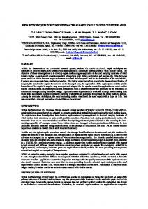
Composite integral armor (CIA) is a multi-functional hybrid lightweight structure that consists of different material layers to provide unique ballistic and structural properties, multi-hit capability, and signature management. Figure 1 shows the schematic of a typical CIA. The composite cover layer protects the ceramic strike face from surface damage and provides confinement. The ceramic strike face is built as an array of hexagonal ceramic tiles supported by a polymeric composite backing plate (inner shell) and, together, they contribute to the structural and ballistic properties of the armor. The ceramic strike face and the composite backing plate are separated by a non-linear rubber layer that has been shown experimentally to increase the armor's multi-hit capability and damage tolerance of the structure (1-4). The U.S. Army has established and documented the requirements for lightweight structural armor that exhibit significant advancements in the integration of ballistic and structural performance (5). Future combat vehicles incorporating CIA must be maintainable and repairable. Composite Cover Layer for Durability, Heat and Detection Avoidance Ground Plane for Signature Alumina Ceramic Layer for Ballistic Requirements Rubber Layer for Ballistic Multihit Requirements Composite Inner Shell Layer for Structural Requirements (S-2 Glass/Vinyl Ester) EMI Layer for Electrical Requirements Special Phenolic Composite Layer for Flammability
Figure 1: Components of a Composite Integral Armor. Ballistic impact can damage the ceramic strike face at lower impact velocities with negligible damage to the composite backing plate. At higher impact velocities, both the ceramic strike face and the backing plate can be damaged such that the ballistic and structural properties of the backing plate are significantly reduced. Studies on repair for renewal of structural properties after ballistic damage have been conducted as part of the Army’s Composite Armored Vehicle program (1, 6). More recently, innovative repair techniques and environmentally friendly resins systems have been developed as part of Army-led efforts through the Strategic Environmental Research and Development Program (SERDP). The work reported here focuses on renewal of ballistic performance after repair. A systematic study has been conducted to assess the effect of delamination and micro damage in the backing plate on ballistic performance, to demonstrate repair methods, and to evaluate the effectiveness of repairs in renewing ballistic performance.
3
2.0
PROCESSING OF CIA
2.1 Materials And Processing The CIA investigated in the present study consists of an arealdensity of 90.33 kg/m3 (18.5 psf). The lay-up sequence is presented in Table 1. This lay-up sequence is used to make single-hit armor panels of dimension 305-mm × 305-mm with a nominal thickness of 36-mm (1.4 in). Table 1: Lay-up Sequence of a 90.33 kg/m3 CIA Material
No. of Layers (Lay-up Sequence)
Composite Cover
7781 E-Glass/SC-15
Ceramic
AD-90, 101.6-mm (4-in) Hexagonal Ceramic Tile 1659 E-Glass Mesh EPDM, Shore - 60 4×4 Plain Weave S-2 Glass/SC-15, 463 Sizing
5 (0º/90º/0º/90º/0º) 1
Scrim Cloth EPDM Rubber Composite Backing
1 1 22 ([(0º/45º/90º/-45º)2/(0º/45º/0º)]S)
A flat tool (steel plate) is cleaned and release agent (Freekote) is sprayed on the surface. Once the tool surface is dry, one layer of breather cloth and peel ply is laid on. A two-unit frame made of wood is used to hold all the layers in place (Figure 2a) and is laid on the peel ply. Another layer of peel ply is laid on the wooden frame. Five layers of 7781 E-glass fabric is cut with dimension 305-mm × 480-mm and laid on the wooden frame according to the lay-up sequence given in Table 1. The 17.78-mm-thick ceramic tiles are arranged such that there is a tile in the center of the panel and this follows that some of the tiles at the edges need to be cut in smaller size to make a 305-mm × 305-mm armor panel. To avoid cutting ceramic tiles, the gaps in the edges are filled with wooden pieces of the same thickness (Figure 2b). The scrim cloth and 1.59mm thick EPDM rubber is placed on next. The scrim cloth provides a controlled bond-line thickness between the ceramic and rubber interface. The rubber layer has 6.35-mm holes 50-mm apart from each other and provides a path for resin to flow through. The rubber surfaces are roughened by a rotary surface grinder using sand paper discs. After cleaning the rubber with soap and water, it is dried and a thin coat of LORD 7701 primer is applied to both surfaces. Plain weave S-2 glass is laid next according to the lay-up sequence in Table 1. The extra length of the cover layer is folded back over the S-2 glass layers (Figure 2c). The assembly is then covered with another peel ply and distribution media. The resin inlet (omega channel) is placed in the middle of the wooden frame and two vacuum lines are placed on the breather cloth outside of the frame. A vacuum bag is placed and the edges sealed with tacky tape. Vacuum is applied to the bag through a vacuum gage mounted resin trap. SC-15 epoxy resin is infused in the part through the resin inlet. The gel time for SC-15 resin is about six hours at room temperature and circulation of resin until gelation is required to maintain vacuum. To minimize resin circulation and waste, a double vacuum bag technique has been developed (Figure 2d). The vacuum is kept on overnight in the second vacuum bag and the part is taken out the following morning (Figure 2e). These CIA panels are post cured in an oven by ramping the temperature to 95 ºC at a rate of
4
2 ºC/min, holding at 95 ºC for 30 min, ramping again up to 125 ºC and holding there for 90 min followed by a cool down at 3-4 ºC /min.
(a) The Wooden Mold
(b) Cover Layer and Ceramic Tiles
(c) Backing Plate Layers and Pre-Implanted Kapton Film Delaminations
(d) Double Bag VARTM Process
(e) CIA Panels after Post-Cure Figure 2: Single-Step VARTM Processing of CIA Panels. 2.2 Pre-Implanted Delaminations It has been identified from earlier ballistic testing of CIA panels that delamination in the backing plate is the most visible macro-damage mode (extensive micro-damage also exists). The effect of delamination on the ballistic performance of the armor can be determined by implanting Kapton film to create delaminations in the backing plate during lay-up. This will provide insight into the ballistic damage tolerance of CIA. Significant research has been conducted to assess the influence of delamination on structural properties of CIA (3) and to quantify the critical delamination size that reduces strength below design requirements. The influence of delamination due to processing or previous impact on ballistic performance has not been studied. Two different types of CIA panels have been processed, the first type (6 armor panels) without any implanted delamination, and the second type (5 armor panels) with six layers of Kapton film (0.05-mm thick) ‘delaminations’ of 100-mm diameter in which seven holes (6.35-mm diameter) are punched (Figure 2c) to facilitate resin flow. The film delaminations are placed between every three layers of S-2 glass fabric along the thickness.
5
3.0
BALLISTIC TESTING OF CIA
These CIA panels are impact tested with machine gun projectiles at a nominal impact velocity of 850 m/sec. The armor panels are clamped on a steel fixture at four corners with C-clamps. Figure 3 shows a schematic diagram of the test fixture. Two pieces of wood (38-mm × 19-mm × 305-mm) are placed in between the armor target and the steel fixture. A 2024 aluminum witness plate (0.51-mm thick) is placed behind the armor target. The impact velocity and residual velocity of the projectile is measured by taking X-ray radiographs at controlled time intervals. The pitch and yaw angles are also measured from radiographs and are found to be minimal and in the range from -2º to 2º. Maximum back face dynamic deflection of the armor is measured from the deformation of the witness plate and the maximum permanent deflection (residual deflection) after spring back is measured directly from the back face of the armor after the projectile impact. The contour of dynamic deflection along a chord of the witness plate is also measured. C-clamp Al Witness Plate CIA Target Impact Wood Spacer
Steel Frame LHS View
Front View
Figure 3: Ballistic Test Fixture. 3.1 Ballistic Damage Evaluation The CIA panels after ballistic impact and penetration have been systematically investigated to identify the damages and associated mechanisms in individual layers. The panels are mechanically dissected layer-by-layer and digital pictures are taken at every step. This dissection process also helped identify the required steps for repair of these impact damaged armor panels. After removing the cover, ceramic and rubber layer, the damaged backing plates are non-destructively tested using ultrasonic C-scan. A one-inch diameter piezo-electric transducer has been used (1.0 MHz frequency). These scans are compared to the scans of undamaged panels to identify macro-damages such as delaminations. 3.2 Results And Discussion The CIA targets without delaminations (designated “B” or “Baseline”) and with implanted delaminations (designated “D” or “Delam”) are identified with numbers from B0 to B5 and D1 to D5, respectively. Figure 4 shows the residual penetration velocities of all targets. Zero residual penetration velocity represents incomplete penetration. Out of six baseline armor targets, complete penetration is observed in three targets (B0, B1 & B5) at the nominal impact velocity (850 m/sec.). Three Delam targets (D2, D3 & D5) were complete at the nominal impact velocity. While these test results are inconclusive (approximately half of the targets of each type is penetrated by the projectile), ballistic performance of the Baseline and Delam armor targets appear similar. These results suggest that the critical delamination size that would significantly reduce ballistic performance would be larger than the 100-mm studied here.
6
Residual Velocity of Projectile, m/sec.
400 B a s e l in e D ela m 300
200
100
0
B0
B1
B2
B3
B4
B5
D1
D2
D3
D4
D5
A rm o r P a n e l N u m b e r
Figure 4: Residual Velocity after Penetration. Impact Velocity = 850 m/sec. The average dynamic deflection contour along the armor diagonal and the maximum residual deflection is presented in Figure 5. The dynamic deflection represents the maximum deformation occurred during the impact event. If the penetration is complete, the dynamic deflection of the central region is obtained through extrapolation. The maximum average dynamic deflection of Baseline and Delam armor targets are found to be 40-mm (Figure 5a). However, the scatter in the Delam targets is more than that of the Baseline targets. The average maximum residual deflection (Figure 5b) of Baseline targets is 6.3-mm and that for Delam targets is 9.2-mm. The higher residual deflection of Delam targets suggests higher permanent macro and micro damages induced in the backing plate, which is not evident from the average dynamic deflection. 60
15 B a s e lin e D e la m Maximum Static Bulge, mm.
Dynamic Deflection, mm.
B a s e lin e D e la m
40
20
0 0
100
20 0
30 0
400
A lo n g D ia g o n a l, m m .
10
5
0
B0
B1
B2
B3
B4
B5
D1
D2
D3
D4
D5
A rm o r P a n e l N u m b e r
(a) Dynamic Deflection along Armor Diagonal
(b) Maximum Static Bulge Figure 5: Dynamic Deflection and Static Bulge.
Two representative recovered backing plates (as described later) are sectioned at impact centerline to examine the extent of delamination and are presented in Figure 6. Wire spacers are used to make all the delaminations visible. Both the Baseline and Delam panels show delaminations extended up to the edge of the panels. However, the delamination of the Baseline panel is distributed close to the impact side, while the Delam panel shows delamination growth only in the plane of pre-implanted delaminations. The uniform distribution of delaminations
7
through the thickness in Delam back plate represents lower bending stiffness as compared to the baseline and explains why the maximum residual deflection is higher.
(a) Baseline – Complete
(b) Delam – Incomplete Figure 6: Cross-Section of Recovered Backing Plate Showing the Extent of Delamination.
(a) Baseline B1 – Complete
(b) Baseline B3 – Incomplete
(d) Delam D3 – Complete (c) Delam D1 – Incomplete Figure 7: Damage and Erosion of the Cover Layer. The extent of damage in the cover layer is shown in Figure 7. The cover layers show damage/erosion of about 50-mm diameter and tearing along in-plane 0º and 90º directions. The diameter of the projectile is much smaller, which indicates that ejected ceramic particles eroded the cover. Extensive damage of the cover is found when the ceramic fracture is severe and most of the surrounding tiles are also damaged extensively (Figure 8). The normal force created by
8
the fractured ceramic confined by the cover and backing plate is sufficient to rupture the cover. The cover layer is carefully removed from the ceramic tiles to match the hexagonal geometry (Figure 8). The damage in the central tile is severe and has been transformed into a fine ceramic powder. However, the surrounding tiles are also badly damaged in some cases. The extent of damage in the surrounding tiles (sympathetic damage) is comparable for both baseline and Delam configurations. Significant difference in the level of sympathetic damage exists between complete and incomplete penetration. The broken ceramic tiles and corresponding rubber layers are then removed. The surrounding wooden pieces are also removed to recover the backing plate.
(a) Baseline B1 – Complete
(b) Baseline B3 – Incomplete
(d) Delam D3 – Complete (c) Delam D1 – Incomplete Figure 8: Damage in the Ceramic Layer. The recovered backing plates are C-scanned and compared with similar backing plates without any damage (Figure 9). The C-scan of the ballistically tested backing plates show wide spread delamination damage, which has also been reported earlier (Figure 6). The extent of impact induced delamination in the Delam panels are similar to that of Baseline, which tells us that only a small area of pre-implanted delamination does not change the overall delamination generated through ballistic impact. Similar dynamic deflection and delamination observed in both the
9
Baseline and Delam CIA panels suggests that the stress wave transmitted to the backing plate ahead of projectile might cause equivalent delamination and micro-damages in both targets.
(a) Baseline – Virgin
(b) Baseline B1 – Complete
(d) Delam D1 – Incomplete (c) Delam –Virgin Figure 9: C-Scan Images of Virgin and Ballistic Damaged Backing Plates.
4.0
REPAIR OF CIA
The repair procedures of thin composite aerospace structures are well developed. Repair of impact induced delaimination and damage in composites can be found (7-11). A general repair guideline for aerospace structures is described in (12). Repair of thick-section composite and integral armor is relatively new. Monib et al (13) used resin infusion method to repair of thicksection composites following the methods described in (14). This method is found suitable for repairing delamination damage in thick-section composite. Three levels of repair for CIA are described in (6 & 15) and are illustrated in Figure 10. These levels are distinguished according to the extent of through-thickness damage in the CIA panel. Level I corresponds to damage in the cover only. Level II includes both cover-damage and fracture of the ceramic. Level III is
10
represented by extensive damage in all layers including the composite backing plate. The requirements for the repair should be to renew strength and ballistic performance to design requirements, the repair should not adversely effect signature management and the repair procedure should be easily carried out with in the field or depot with the Army’s existing facillities and manpower. Level I: Remove and Replace Cover Layer
Level II: Remove and Replace Cover Layer and Tile
Level III:
Remove Cover Layer and Tile, Infuse Backing Plate, Replace Cover Layer and Tile
Figure 10: Repair Hierarchy Level I repair of the damage in the cover layer is fairly simple. The cover is removed with a router and replaced with an adhesively bonded flush mounted patch and gaps are filled for signature purposes. Level II requires the removal and replacement of all cover, cracked ceramic tiles and the rubber layer. In this case, the surface of the composite must be machined flat to provide uniform support of the tiles. Each layer is replaced and adhesively bonded. Level III requires the additional repair of the backing plate. In our Level III repair strategy, resin infusion of the delaminated backing plate is used. A vacuum bag is used to apply compaction pressure for all three levels of repair and thermally cured. Ballistic testing of the repaired panels provides some insight into the effectiveness of Level III repair to renew ballistic performance. Details of this repair procedure are summarized next. Four recovered backing plates of the Baseline CIA panels (B0-B3) are re-infused with SC-15 resin using the VARTM technique. A 12-mm diameter hole was drilled at the impact site approximately three-quarter the thickness of the backing plate in depth (Figure 11a). Six more holes (3-mm diameter) were also drilled around the impact center at a radius of 50-mm. A vacuum bag is applied and resin is infused in the central hole while the vacuum port placed on the smaller holes. One such part is infused with colored resin and sectioned to examine the extent of resin infusion. Figure 11b shows that the infused resin filled the delaminations efficiently. This method is applicable for partial penetrations that do not require access to the back surface of the backing plate (i.e. interior). For comparison purposes, backing plates recovered from the Delam panels (D1-D4) were not repaired via VARTM (Level II only) to study the effect of resin-infusion repair of backing plates. The ceramic tiles and cover were added on the backing plates by a hand lay-up technique and a vacuum bag was applied later to provide sufficient compaction pressure. The repaired CIA panels are post cured following the cure cycle described earlier. The repaired baseline and Delam CIA panels are designated as B0R to B3R and D1R to D4R respectively, where ‘R’ is used to designate ‘repair’.
11
(a) Drilling Holes
5.0
(b) Infused Backing Plate Figure 11: Repair of Backing Plate
BALLISTIC RE-TESTING OF REPAIRED CIA
The repaired CIA panels are ballistically re-tested with the same projectiles with a nominal velocity of 850 m/sec. The test fixture and mounting boundary conditions were identical to the first ballistic tests. The residual velocities are measured to determine the effect of Level II and Level III repair on the ballistic performance. The residual penetration velocities of the various CIA targets is presented in Figure 12. Also included in this figure are the initial results for the baseline and pre-delaminated targets for comparison. Three out of four repaired Baseline panels (B0R, B2R & B3R) and all repaired Delam panels (D1R to D4R) showed complete penetration. The average residual velocity of the repaired Baseline (complete) panels is found to be 295 m/sec, where as the average residual velocity of such virgin panels (Baseline – complete) is 277 m/sec. This observation demonstrates significant renewal of ballistic properties of CIA panels after Level III repair. The average residual velocity of the repaired Delam (complete) panels is 467 m/sec, which is much higher than that of the virgin Delam (complete) panels (310 m/sec). The backing plates of these targets were not infused with resin and the projectile impact was centered on the previous impact damage to simulate the worst-case scenario. This demonstrates the importance of backing plate repair (resin infusion) on the global ballistic performance of repaired CIA targets.
6.0
SUMMARY
Single-step VARTM processing of CIA has been used to fabricate 90.33 kg/m2 CIA targets with and without pre-implanted delaminations. . The CIA targets are ballistically tested with machine gun projectiles at a nominal impact velocity of 850 m/sec. The influence of embedded delaminations on ballistic performance has been evaluated. Both the Baseline and Delam targets exhibit similar residual velocity after penetration, dynamic deflection and extent of delamination in the backing plate, however, the Delam panels has higher residual deformation after impact. These results indicate that CIA is ballistically damage tolerant and the critical delamination size (e.g. manufacturing or previous impact damage) that would significantly reduce ballistic
12
performance would be larger than the 100-mm studied here. Previous studies have shown that the stress wave propagation in advance of the projecticle will cause extensive delamination of the backing plate approximately the same size as the tile (100-mm). This could be one possible explantion for why the embedded delaminations do not degrade ballistic performance in this case. The repair strategies suitable for CIA repair have been discussed for three levels of repair. VARTM repair of the backing plate has been demonstrated. Ballistic performance by Level II and Level III repairs has been quantified by measuring residual penetration velocity. Results show that Level II repair is not sufficient to renew ballistic performance to original levels. Level III repair exhibits comparable residual velocity to the baseline and shows potential for complete renewal of ballistic properties.
Residual Velocity of Projectile, m/sec.
500
400
300
200
100
0
B0
B1
B2
B3
B 4 B 5 B0 R B1 R B2 R B3 R
D1
D2 D3
D4
D 5 D 1 R D 2 RD 3 R D 4 R
A rm o r P a n e l N u m b e r
Figure 12: Residual Velocity after Penetration of Virgin and Repaired CIA.
6.0
ACKNOWLEDGMENT
The authors wish to acknowledge the financial support provided by the Strategic Environmental Research and Development Program (SERDP Grant No. DAAL01-98-K-0058) and the Tuskegee University (TU Grant No. AGR 19951129). The authors are also grateful to Drs. James Sands and Steven H. McKnight of the Army Research Laboratory and Dr. Shridhar Yarlagadda of the Center for Composite Materials at the University of Delaware for their technical input related to composite processing and repair of the CIA panels. A special thanks is given to Ms. Melissa Klusewitz and Mr. Mathew Burkins (both from the Army Research Laboratory) for their technical expertise in performing all of the ballistic testing in support of this work.
13
7.0 1. 2.
3.
4.
5. 6. 7. 8. 9. 10. 11. 12.
13.
14.
REFERENCES
Composite Structure Design Guide, Composite Armored Vehicle Program, United Defense L. P., 1997-98. B.K. Fink and J.W. Gillespie Jr., “Cost-Effective Manufacturing of Damage Tolerant Integral Armor,” Technical Report (in press), US Army Research Laboratory, Aberdeen Proving Ground, MD 21005, 2000. A.M. Monib, J.W. Gillespie Jr. and B.K. Fink, “Damage Tolerance of Thick-Section Composites subjected to Ballistic Impact,” CCM Report, No. 99-08, University of Delaware, 1999. B.A. Gama, J.W. Gillespie Jr., H. Mahfuz, T.A. Bogetti and B.K. Fink, “Effect of NonLinear Material Behavior on the Through-Thickness Stress Wave Propagation in MultiLayer Hybrid Lightweight Armor,” Paper accepted for International Conference on Computational Engineering & Science, Los Angeles, CA, August 2000. B.K. Fink, J. of Thermoplastic Composite Materials, submitted, May 2000. Design Guide, Composite Armored Vehicle Advanced Technology Demonstrator (CAVATD), United Defense L. P., April 1998. M. Motuku, U.K. Vaidya and G.M. Janowski, Smart Materials and Structures, 8(5), 623 (1999). A.J. Russel, C.P. Bowers and A.J. Moss, International Conference on Composite Structures, Elsevier Science Publ Ltd., 1991, pp. 145. J. Paul and R. Jones, Engineering Fracture Mechanics, 41(1) 127 (1992). W.I. Cantwell, P. Davies and H.H. Kausch, SAMPE J., 27(6) 30 (1991). C-L. Ong, M-F. Sheu and Y-Y. Liou, International SAMPE Symposium and Exhibition, 34(1) 458 (1989). General Composite Repair – Organizational and Intermediate Maintenance: Technical Manual, Naval Air Systems Command Report No. NAVAIR 01-1A-21, Final Draft, December 1993. A.M. Monib, J.W. Gillespie Jr. and D.J. Wilkins, “Assessment of the Effectiveness of Resin Infusion Repair Techniques on Thick-Section Composites,” CCM Report No. 9627, University of Delaware, 1996. S.P. Wanthal, “Delamination Methodology for Composite Structures,” NAWCADWAR94137-60, Vol. I & II, McDonnel Douglas Co., 1994.