use cases for product line modeling they have to be extended with a vari- ... approach with an example, a âcruise control systemâ that is a part of the automotive.
Product Line Modeling with Generic Use Cases Isabel John, Dirk Muthig Fraunhofer Institute for Experimental Software Engineering (IESE) Sauerwiesen 6, D-67661 Kaiserslautern, Germany +49 (0) 6301 707 - 250 {Isabel.John, Dirk.Muthig}@iese.fhg.de Abstract1
Use cases are used for single system requirements engineering to capture requirements from an customer/user point of view. When utilizing use cases for product line modeling they have to be extended with a variability mechanism. Stereotypes can be used as this variability mechanism for use case diagrams and textual use cases. This early and explicit variability in the product line lifecycle supports the domain experts in establishing a variability mindset and supports explicit instantiation during application analysis
1 Introduction During the last decade reuse has been recognized as a key factor for improving software development efficiency. Product line engineering is a reuse approach providing methods to plan, control, and improve a reuse infrastructure for developing a family of similar products. The goal of product line approaches, such as PuLSETM [2] is to achieve planned domain-specific reuse by building a family of applications rather than developing products separately. Generally, it is not reasonable to build a product line from scratch without having a broad area of expertise in the domain of the product line. The ability to think in terms of a product line, and find variabilities within an application domain requires a certain depth of domain understanding. The domain understanding is defined as follows: “Domains are areas of expertise that can be applied to the creation of a system or set of systems. Domain knowledge is characterized by a set of concepts and terminology understood by practitioners in that area of expertise” [4]. During the domain-analysis phase of domain engineering the common and varying requirements of the planned set of products are built. Use cases are a widely accepted means to support domain understanding, find, and document user requirements but there is no generally accepted formalism that integrates variability modeling with use cases. Expressing variability in the use cases has benefits in the following ways:
1
This work has been partially funded by the Empress project (Eureka Σ! 2023 Programme, ITEA project 00103)
- Seeing variability in the use-cases helps all involved roles in establishing a variability and product line mindset and in getting a better domain understanding - Explicit variability in use cases supports the instantiation and derivation of exact models in application engineering - In market development which is not customer oriented, variable use cases are a good means of communicating the possibilities of the possible products between marketing and requirements engineers and product line engineers 1.1 Related Work There are some approaches on how to extend use cases with variability and how to support reuse and genericity in use cases. Biddle et.al. [3] suggest to use patterns in use cases to express variability and to organize the use cases in a repository. However, they do not introduce variability. Gomaa [6] introduced in his method the stereotypes and for use cases and other UML model elements for modeling families of systems. In his approach he focuses on the integration of features and use cases but does not say anything about how textual use cases should be represented. Jacobson et.al. [8] discuss how the text in use cases may involve variation points that can form the basis for a hierarchy of use cases from more abstract to more specific. They introduce “variation points” (notated as dots in use cases including a short description of the variation) into use case diagrams. They also use variation points in textual use cases (notated as highlighted text in curly brackets) to describe different ways of performing actions within a use case and also discuss the use of include and extend relationships. They do not say anything about how variant or generic use cases can be instantiated. Our approach is derived from the KobrA approach [1], which introduces variation points in the UML including use cases and supports the instantiation of generic models. 1.2 Outline In this paper we describe how commonality and variability can be integrated and described in use-case diagrams and textual use-case descriptions. We illustrate the approach with an example, a “cruise control system” that is a part of the automotive domain. A cruise control system supports the driver in keeping a constant velocity and does real time monitoring and control of the cars speed. It exists in variants that have or have not a distance regulator, which controls the distance between the car to the car(s) ahead and behind. The remainder of this paper is structured as follows: In section 2 we describe how requirements engineering with use cases is done for single systems and introduce the single-system version of our example. In section 3, we will describe product-line concepts and apply them to the example. The paper concludes with some final remarks.
2 Single System Use Cases 2.1 Requirements Engineering with Use Cases Requirements Engineering for single systems has been done for a long time. Formalism which have been used for a long time are e.g. textual requirements, controlled languages, formal or semi-formal specification languages like SDL or Z. For some years use cases [7] have been a means to understand, specify and analyze user requirements that is rather often used. Use cases can document the requirements on a system from a users point of view. Use cases focus on functional requirements, they normally do not deal in depth with non-functional requirements, with interfaces and data formats. But use cases make it easier to understand what the system does and give a good means of communication about the system. 2.2 Use-Case Diagrams A use case describes how the system is used by a user. Use cases are used during the analysis phase to identify and partition system functionality. A use case describes the actions of an actor when following a certain task while interacting with the system to be described. A use case diagram includes the actors, the system, and the use cases themselves. The set of functionality of a given system is determined through the study of the functional requirements of each actor, expressed in the use cases in the form of common interactions. So a use-case diagrams in UML 1.4 consists of [9]: - The system - The use cases within the system - The actors outside the system - Relationships between actors and use-cases: associations, generalization, include, and extend Associations denote the participation of an actor in a use case, a generalization relation means that there is a specialization of one use case or actor to another. An extend relationship indicates that an instance of a use case may be augmented by the behavior specified by another use case and the include relationship indicates that an instance of a use case will contain the behavior of another use case.
Cruise Control System
deactivate cruise control
Set Velocity gas regulator
keep velocity Driver
«include» «include»
readopt velocity
rotation sensor calculate velocity
timer
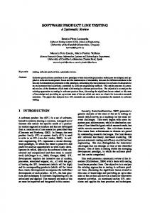
Figure. 1. A use case diagram for a cruise control system
Figure 1 shows an example use case diagram for a cruise control system. The driver activates the cruise control system by choosing “set velocity”. He can also tell the system to “keep velocity” with help of the gas regulator if the velocity has already been set. He can also “readopt velocity” which will bring the car to the fixed speed (e.g. after braking) and then continue keeping the velocity. In order to keep the velocity the system has to “calculate velocity” with different sensors. 2.3 Textual Use Cases There is no standardized form for the content of a use case itself, the standard describes the graphical representation and the semantics of use case diagrams only. Use cases are fundamentally a text form although they can be written using flow charts, sequence charts or petri nets [5]. Use cases serve as a means of communication from one person to another, often among persons with no training in UML or software development like end users or marketing staff. So writing use cases in simple text is usually a good choice. There is no general agreement on the attributes use cases should have and on the level of description of the use cases. Figure 2 shows an example of a textual use case in the cruise control domain which describes the use case “keep velocity”. The template used is a modification of the template suggested by Alistair Cockburn (see [5]). The use case is described with its actors, the triggers, which means the actors that can activate the use cases. The input and output of the use case are described and the postconditions and a success guarantee (what the user wants from the use case) and a minimal guarantee (what should in any case not go wrong) are given. The main part of the use case is the main success scenario which describes what the use case actually does.
Use Case Name: keep velocity Short Description: keep the actual velocity value over gas regulator Actors: driver, gas regulator Trigger: actor driver Precondition: -Input: starting signal, velocity value vtarget Output: infinit Postcondition: vactual = vtarget Success guarantee: vactual = vtarget Minimal guarantee: The car keeps driving Main Sucess Scenario: is selected by actor driver get vactual, vtarget () - compare vactual and vtarget If vactual < vtarget : gas regulator increase velocity - restart If vactual < vtarget : gas regulator decrease velocity - restart else restart Figure. 2. A use case for “keep velocity” of the cruise control system
3 Product Line Use Cases In this section, the use case approach is extended to product families, that is, use cases do not longer describe the actions of an actor when following a certain task while interacting with a particular system only but summarize and integrate use cases describing analogous tasks for different products in a family into combined artifacts, product-line use cases. Before describing in Section 3.1 the required extensions to the two artifacts, use-case diagram and textual use-case descriptions, described above, the main product-line concepts are introduced. 3.1 Product Line Concepts From an abstract point of view it is the concurrent consideration, planning, and comparison of similar systems that distinguishes product line engineering from single-system development. The intention is to systematically exploit common system characteristics and to share development and maintenance effort. In order to do so, the common and the varying aspects of the systems must be considered throughout all life-cycle stages and integrated into a common infrastructure that is the main focus of maintenance activities. Commonalities and variabilities are equally important: commonalities define the skeleton of systems in the product line,
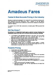
variabilities bound the space of required and anticipated variations of the common skeleton. Applied to use cases, these concepts produce use cases that have a common story that is valid for all members of a system family with variation points that explicitly capture which actions are optional or alternatives. Of course, a use case as a whole may be optional, as well as use cases under the same label may be realized totally different for some products. The common parts are modeled as all parts in a single-system context, to model variation, additional means are required. The variant use cases are instantiated during application engineering. The instantiation process is guided by a decision model, which captures the motivation and interdependencies of variation points, and produces use case artifacts as used in a single-system context (see previous section). In the following subsections, one way of modeling variation in use-case diagrams and textual use case descriptions is introduced. 3.2 Generic Use Case Diagrams In use case diagrams, any model element may potentially be variant in a product-line context. An actor is variant, for example, if a certain user class is not supported by a product. A use case is variant if it is not supported by some products in the family. Those variants can be alternatives, optional elements or value ranges for certain elements. Whether it is an optional use case or whether it is an alternative to another use case is captured outside of the use-case diagram in a decision model. This is done simply because this information would overload the use-case diagram, make it less readable, and thus less useful. A generic use case diagram for our cruise-control example is depicted by Figure 3. There, an optional distance regulator has been added, that is, four additional (and variant) use case have to be modeled by using the stereotype , as well as an additional actor, the optional radar sensor to measure the distance of a car in front.
The additional feature has an impact on other use cases, which is modeled in the textual description of the affected use cases. An example for the use case “keep velocity” is given in the following subsection. Cruise control system with optional distance regulator deactivate cruise control
Set Velocity gas regulator
keep velocity Driver
«include» «include»
readopt velocity
«extend» calculate velocity
rotation sensor
«variant» Set distance
«variant» calculate distance
timer
«include» «variant» deactivate dist. regulator
«variant» keep distance
«variant» radarsensor
Figure. 3. Generic Use Case Diagram
During application engineering, for each variant use case, it is decided whether the use case is (or is not) supported by the product to be built. The instantiation is done then with the help of the decision model. Further information on decision modeling can be found in [1]. If a cruise control without distance regulator is built, all the variant use cases are removed, and the resulting use case diagram is the diagram shown in Figure 1.
3.3 Generic Textual Use-Cases In a textual use case description any text fragment may be variant. Variant text fragments are explicitly marked by pairs of the XML-like tags and . Figure 4 shows an example of this approach, the use case “keep velocity”. Use Case Name: keep velocity Short Description: keep the actual velocity value over gas regulator by controlling the distance to cars in front Actors: driver, gas regulator Trigger: actor driver, actor distance regulator Precondition: -Input: starting signal, velocity value vtarget Output: infinit Postcondition: vactual = vtarget Success guarantee: vactual = vtarget Minimal guarantee: The car keeps driving Main Sucess Scenario: 1.) is selected by actor driver 2.)get vactual, vtarget () 3.) Does a distance regulator exist? get dactual, dtarget () 4.) Does a distance regulator exist? - compare vactual and vtarget If vactual < vtarget : gas regulator increase velocity - restart If vactual < vtarget : gas regulator decrease velocity - restart else restart - - compare vactual and vtarget If vactual < vtarget : gas regulator increase velocity - restart If vactual < vtarget and atarget £ aactual: gas regulator decrease velocity - restart If vactual < vtarget and atarget > aactual: gas regulator increase velocity - restart else restart
Figure. 4. Generic Use Case Description
The underlined questions in the use cases reflect the parts of the overall decision model that are relevant for this particular use case. This information is useful in both workproducts: integrated in the use case description, it helps to understand the use
case’s variability from the use-case’s point-of-view, in the decision model, it helps to understand the variability of the whole product family and what the impact of a particular variability is (e.g., it has an impact on this use case). Hence the overall decision model captures the relationship between the decisions related to the above generic use case diagram and the textual description in Figure 4. That is, if the feature distance control is excluded the four variant use cases are removed and all variant text fragments are removed from the description of the use case “keep velocity”, as well as the first alternative for step 4 is selected. This instantiation leads to the use case description given in the previous section.
4 Conclusions In this paper, we described how use cases can be applied for modeling the requirements for a system family. Therefore, we showed how a particular single-system use case approach can be extended to capture product line information and especially variability.By making explicit this variability in the use cases, this variability can be communicated to all relevant groups (requirements engineers, product managers, management staff..), a variability mindset is established and a controlled derivation of application models can be supported. The approach has been illustrated by the running example “cruise control system”. In our experience, use cases are a good means to elicit, structure, and represent userlevel information during the requirements phase. Extended with variation points, they also allow people to easily switch from single-system requirements-engineering practices to domain analysis. The produced generic use-cases also support and guide application engineering (in particular, its requirements phase). Thereby, each variation point must be instantiated, that is, generic use-case with variation points are systematically transformed into "normal" single-system use-cases as they are expected by individual customers. The approach makes explicit the functionality of the system from the enduser perspective which might be complementary to conventional feature modeling focusing on end user features. In general, the described approach pushes the explicit consideration of variability to the early phases of product-line development, which is required to systematically manage and evolve a product-line infrastructure. With the right decision model that captures the relationships and dependencies among variation points, the approach captures the traceability paths from variant use-case actions down to variant implementation elements.
Acknowledgements We want to thank Stefan Sollmann who provided the cruise control example and supported us in modeling the use case diagrams and the use cases.
References [1] [2]
[3] [4] [5] [6] [7] [8] [9]
C. Atkinson, J. Bayer, C. Bunse, E. Kamsties, O. Laitenberger, R. Laqua, D. Muthig, B. Paech, J. Wst, and J. Zettel. Component-based Product Line Engineering with UML. Component Software Series. Addison-Wesley, 2001. J. Bayer, O. Flege, P. Knauber, R. Laqua, D. Muthig, K. Schmid, T. Widen, and J.-M. DeBaud. PuLSE: A Methodology to Develop Software Product Lines. In Proceedings of the Fifth ACM SIGSOFT Symposium on Software Reusability (SSR’99), Los Angeles, CA, USA, May 1999. ACM. R. Biddle, J. Noble, and E. Tempero. Supporting Reusable Use Cases. In Proceedings of the Seventh International Conference on Software Reuse, Apr. 2002. P. Clements and L. Northrop. Software Product Lines : Practices and Patterns. Addison Wesley, 2001. A. Cockburn. Writing Effective Use Cases. Addison Wesley, 2001. H. Gomaa. Object Oriented Analysis and Modeling for Families of Systems with UML. In W. B. Frakes, editor, Proceedings of the Sixth International Conference on Software Reuse, June 2000. I. Jacobson. Object-Oriented Software Engineering, A USE Case Driven Approach. Addison Wesley, 1992. I. Jacobson, M. Griss, and P. Jonsson. Software Reuse. Architecture, Process and Organization for Business Success. Addison-Wesley, 1997. Object Management Group. OMG Unified Modeling Language Specification, Version 1.4, September 2001.