ming CPS applications through simulation and experiments run on a mote testbed, configured to accurately emulate a network of PTZ cameras in a distributed ...
Programming Support for Distributed Optimization and Control in Cyber-Physical Systems Rahul Balani, Lucas F. Wanner† , Jonathan Friedman, Mani B. Srivastava Electrical Engineering, † Computer Science University of California Los Angeles, USA {rahulb, wanner, jf, mbs}@ucla.edu
Abstract—Large-scale actuator control problems in CyberPhysical Systems (CPSs) are often expressed within the networked optimization model. While significant advances have taken place in optimization techniques, their widespread adoption in practical implementations is impeded by the complexity of inter-node coordination and lack of programming support that is necessary for sharing information coherently between distributed and concurrent controller processes. In this paper, we propose a distributed shared memory (DSM) architecture that abstracts away the details of inter-node coordination from the programmer resulting in simplified application design. It maintains data coherency through explicit use of mutual exclusion lock primitives that serialize access to coarse subsets of shared variables using fine-grained read/write permissions. The underlying lock protocol is deadlock-free, fair and safe, and reduces response time and message cost by 81.6% and 72.8% respectively over a conventional DSM implementation with coarse access permissions. Moreover, in a representative application example, the proposed framework reduces application code size by 76% and total latency by 22% over a hand-crafted implementation. Keywords-Subgradient method; Distributed Shared Memory; Coherence; Mutual Exclusion; Sensor/Actuator Networks
I. I NTRODUCTION Actuator control problems in several important CPS applications - such as water-efficient irrigation [1], energyefficient HVACs, self-reconfiguring visual surveillance [2] and personalized light control [3] - are often expressed as optimization of a cost function involving current state of the environment, as inferred from sensor measurements, and control inputs of actuators. Distributed controllers implement optimization algorithms to continuously drive the physical state of the world towards application specific goals by iteratively estimating optimal control inputs of each actuator. Henceforth, we interchangeably refer to these control inputs as actuator variables (or just variables for simplicity). Parallel controller processes often require coherent access to common actuator variables such that the result of any distributed execution is equivalent to some sequence of estimations (and actuations) in each iteration of the algorithm (serializability) [2][4][5]. This is necessary for (timely) convergence of the algorithm when each controller produces
Kaisen Lin, Rajesh K. Gupta Computer Science University of California San Diego, USA {kaisenl, gupta}@cs.ucsd.edu
new estimates based on sensor measurements as well as current estimates of adjacent and shared actuator variables. This requirement is unique to CPSs, as traditional sensor network applications require read-only access to shared information. Moreover, convergence to sub-optimal values in CPSs can cause persistent and often expensive side-effects in the environment such as over-watering in agriculture [1], missed events in security surveillance of airports [2], energy wastage in HVAC systems, and damage to the marine ecosystem through waste water overflow in sewers [6]. Currently, application developers must build their own elaborate inter-node coordination mechanisms required for data coherency. Moreover, little of this intricate machinery carries over directly from one application to the next as it encapsulates application-specific design choices in terms of identification and management of shared variables for each controller. These choices are deeply influenced by (i) the relationship between actuators as defined by their physical properties and relative poses in the deployment; and (ii) network characteristics like topology and communication modality that determine the performance of the distributed algorithm. In this paper, we introduce the Hotline programming framework that allows application developers to implement concise yet efficient distributed programs for individual actuator controllers (nodes) using shared memory abstractions and lock primitives that guarantee serializability. Similar to the Release Consistency (RC) model in DSMs, any read or write access to shared actuator variables is guarded by explicit lock acquire and release operations at respective nodes. However, instead of arbitrating locks at the fine granularity of individual variables, Hotline administers locks at a coarser granularity of subsets of variables. This avoids the run-time overhead of deadlock detection and resolution that is typical of DSMs managing concurrent fine-granularity access in presence of communication delays and losses [7]. This design is natural for the class of algorithms that Hotline aims to support and does not sacrifice any inherent parallelism in data access due to coarse granularity locks. In fact, a key feature of Hotline is that it can exploit
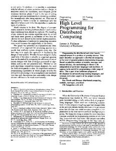
localized data dependencies between distributed processes, inferred from fine-grained access permissions specified by the programmer, to speed up each iteration of a distributed optimization algorithm through opportunistic data parallel operation. It is based on the critical observation that an estimation process at a controller accesses the control inputs of only a local subset of actuators. This is true in many CPS applications where actuators are deployed with planned but localized overlap in their regions of influence (zones) to achieve complete geographic coverage. As a result, each controller needs to coordinate the effect of multiple actuators that overlap at a point, or an area, in space such that the desired result is produced in that region. Hotline caches shared actuator variables locally at the respective controllers and synchronizes them at lock release operation to optimize data access latency. This process is transparent to the programmer who addresses each variable simply through a (key, actuator id) tuple and is guaranteed consistent access to it by the Hotline run-time library. In addition, multiple network topologies are supported for efficient data synchronization depending on the set of participating nodes. We demonstrate the utility of this framework in programming CPS applications through simulation and experiments run on a mote testbed, configured to accurately emulate a network of PTZ cameras in a distributed surveillance application, and a network of light sensors and dimmable light sources in an office space. The framework has been implemented in TinyOS-2.x. Our experimental results on mote testbeds show that code size is reduced by up to 76% over hand-crafted code and latency in calculating optimal control inputs is lowered due to data parallel operations. Our extensive simulations using TOSSIM demonstrate that the synchronization algorithm is scalable to a large number of nodes in presence of intermittent communication failures. II. S YSTEM D ESIGN A. Coarse Physical Resources Hotline associates each controller at node i with a set σ(i) of all variables that the node will need to access in an iteration of a distributed optimization algorithm. Each unique set σ(·) is therefore represented collectively as a single physical resource that can be locked by a node before the beginning of every iteration. It is formally defined as σ(i) = {uk | k ∈ UA } , (1) where uk is the control input of an actuator k, and UA is the set of actuators which can influence the state of environment in a local region A that is of interest to node i. Figures 1 and 2 show this set of actuators for each controller in personalized light control and automated visual surveillance respectively. Resources can be identified statically through compiletime specification of UA for each controller, or discovered
Light Sources u1
u2
u3
Light Sensors & Controllers Resources
[u1]
[u1,u2]
[u2]
[u2,u3]
[u3]
Access
[W] L1
[W,W] L2
[W] L3
[W,W] L4
[W] L5
Figure 1. Network of sources (u*) and sensors+controllers (L*) for personalized light control. Edges between controllers show direct resource conflicts.
Controller: Resource: Access:
3 [u3, u2, u8] [W, R, R]
7 [u7, u2, u8, u1] [W, R, R, R]
Figure 2. A network of Pan-Tilt-Zoom (PTZ) cameras used for distributed visual surveillance. Gray sectors show camera zones. Edges show direct resource conflicts. Controllers 3 and 7 can operate concurrently in Hotline due to to compatible access permissions, but not in a DSM with coarse permissions.
dynamically through continuous rule-based application at each node to support run-time modifications in the deployment due to mobility or faults. In dynamic rule-based operation, a set UA can be expressed and discovered in terms of influence zones γ of actuators as UA = {k | A ∩ γ(k) 6= φ} .
(2)
A zone represents the physical space that can be affected by an actuator like a sprinkler, light etc., within a specified period of time and range of configuration parameters. It is affected significantly by the physical context of the device such as location and orientation. This definition can also be extended to represent a region that can be sensed by an actuator-assisted sensor like a PTZ camera as shown in Figure 2. An application programmer is only responsible for defining actuator zones and regions of interest A while the run-time transparently discovers and manages resources resulting in a concise implementation.
B. Fine-grained Access Permissions
C. Local Caches
While a resource σ(i) is locked as a single unit, Hotline allows each member variable uk to be accessed via distinct READ or WRITE permissions specified apriori by the programmer as τ (i, uk ). Hotline arbitrates between concurrent lock requests such that, at any time, at most one node can access a variable with WRITE permission. This is referred as the safety property in this text and is necessary for Hotline to ensure coherency by serializing writes to individual variables. However, multiple nodes can simultaneously access a shared variable with read-only permissions when no other node has locked it with WRITE permissions. Hotline incorporates this rule by prohibiting concurrent locks on directly conflicting resources. A pair of resources σ(i) and σ(j), conflict (directly) if they have a non-empty intersection, and a node needs to access at least one common variable with a WRITE permission. To formalize the concept of conflicts, we first define a commutative operator as
Hotline caches shared actuator variables locally at the respective controllers to optimize data access latency. Following an eager RC model, any updates to a local cache are synchronized across all relevant copies during the lock release operation. This model is favored over lazy RC schemes that synchronize updates at the next lock acquire operation as each node undergoes multiple iterations, and subsequently another node is already waiting to complete its lock acquire operation on a conflicting resource. As a result, it minimizes the expected time a node has to wait for consistent data access. An interesting property of the associated graph G is that it also defines the extent to which updates originating at a node must propagate to achieve cache coherency. These are the set of nodes that are adjacent to the source of update, and due to local data dependencies, they are also spatially localized resulting in a low message cost for update synchronization. Although the distributed lock protocol has been designed such that its messages can trivially incorporate data synchronization to further decrease the above message cost, they are consciously kept separate in our current implementation to minimize lock synchronization latency in networks with small link MTUs such as 802.15.4.
i j = {uk | uk ∈ σ(i)∩σ(j), Ω(i, j, uk ) holds} ,
(3)
where, boolean property Ω(i, j, uk ) holds true when at least one of nodes i and j need to access the common variable uk with a WRITE permission. As a result, the operator returns the set of common variables uk in resources σ(i) and σ(j) that have conflicting access permissions desired by the operands. Thus, resources σ(i) and σ(j), or concurrent lock requests for these resources, are conflicting iff i j 6= φ. This creates lock/data dependencies in a network of controllers that can be analyzed by associating a graph G = (V, E) with the network, where V = {1, .., N } is the set of N controller nodes or graph vertices, and E = {(i, j)|i j 6= φ, ∀i, j ∈ V} is the set of edges that represent direct resource conflicts between corresponding end points (Figures 1 and 2). However, in many CPS applications, we observe that the resource conflicts are spatially localized in nature due to localized actuator overlaps. Consequently, nodes with non-conflicting resources can operate in parallel resulting in reduced application latencies. Moreover, Hotline’s unique arbitration of coarse locks based on fine granularity access permissions promotes parallelism by reducing the potential number of conflicts as compared to a conventional scheme with coarse permissions. Nevertheless, the problem of finding the optimal order of lock grants that maximizes concurrency in access to shared varaiables is shown to be equivalent to the graph coloring problem for G [2] which is provably NP-complete. Since efficient distributed heuristics for graph coloring, proposed in the literature, are hard to implement on resource constrained sensor-actuator nodes, researchers have instead used randomized best-effort solutions. Hotline follows the same approach and uses a simple randomized solution to optimize concurrency at run-time.
III. D ISTRIBUTED L OCK A RBITRATION Hotline uses PhyLock, a distributed permission-based protocol where each node requesting lock on a resource must communicate with every member of an associated coordination clique to convey the request, obtain permissions, and release the lock when it is done. PhyLock associates a unique priority β(i) with each new request for σ(i) to avoid deadlocks (Liveness) when multiple nodes request simultaneous access to resources. The priority is a (sequence, identifier) tuple, where a lower sequence number has a higher priority, but in case they are equal, unique node identifiers are used to break the tie by selecting the node with a lower identifier. Sequence numbers can be set using global timestamps with a time sync protocol like FTSP (default), Lamport’s logical clocks [8] or Maekawa’s sequence numbers [9]. In this section, we describe PhyLock’s selection of cliques, explain the distributed protocol and analyze its performance in terms of latency and message cost. Section III-C proves that the algorithm satisfies the following properties in presence of recoverable communication failures: (P1) Safety, (P2) Liveness, and (P3) Fairness. A. Coordination Cliques In PhyLock, the clique ξ(i) for a node i is defined as the set of all nodes associated with conflicting resources, and is equivalent to the set of adjacent nodes in graph G. Formally, it can be expressed as ξ(i) = {j | i j 6= φ, i 6= j} ∪ {i}. (4)
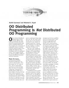
The cliques defined above satisfy the following properties: • C1: ξ(i) ∩ ξ(j) 6= φ. In order to arbitrate any pair of two concurrent and conflicting requests from arbitrary nodes i and j, they must reach at least one common node for correct resolution. This is a necessary condition to prove P1 as shown by [9]. • C2: {i, j} ⊆ ξ(i) ∩ ξ(j). This encapsulates C1 and is sufficient to prove P1 as shown in Section III-C. This is a stronger property, and theoretically, one can argue that it incurs a run-time overhead in terms of message exchange due to bigger clique (quorum) sizes as compared to other quorum-based mutex protocols like [9]. However, in practice, constructing a quorum in a distributed fashion is non-trivial and costly [10]. Therefore, PhyLock sacrifices reduction in message exchanges, if any, for a simple clique formation and management at run-time. An alternate but naive selection of cliques for each node, that satisfies C2, can be the set of all nodes N in the network. It reduces the PhyLock protocol to Ricart and Agrawala’s mutex algorithm [11] that requires O(N ) messages for resource arbitration. However, this is very inefficient for many CPS applications where |ξ| � N . Another selection of clique for a node i, that satisfies C1, can be the set of actuators whose control inputs comprise the resource σ(i). But, in the presence of communication delays or losses, it can result in deadlocks unless the actuators coordinate amongst themselves to avoid or break the deadlocks. This actuator coordination can be trivially supported in our system by reversing the roles and defining resources for each actuator as the set of controller nodes requesting access to it. However, this is sub-optimal as actuators will have to keep extra state for concurrent requests from controllers besides the state required for coordinating with other actuators. B. Algorithm Each node executes an identical PhyLock algorithm. It is based on the fact that, if node i receives permission to access its resource σ(i) from all the nodes in its clique ξ(i), no other node can lock any conflicting resource. PhyLock uses timeouts and retransmissions to ensure reliability in face of communication losses. The subsequent text describes default behavior of the protocol for supporting priority based execution as shown in Figure 3. A node is always in an idle state when not requesting any locks. • S1: When a node i attempts to acquire a lock, a REQUEST message with a new priority is sent to every member of ξ(i). A timer is started for period Treq . • S2: Upon receiving a REQUEST, a member node of ξ(i) responds with a REPLY message if it is idle, or its request priority is lower than the newly received request (yield). However, if its priority is higher than the received request, or if it already holds a lock, then it marks the request as pending and defers the REPLY until it finishes accessing the locked resource.
[S2] Rx REQ
IDLE
Tx REPLY [R1] acquire() Rand. WAIT [R2] Trans. conflicts
[S1] acquire()
Tx INQUIRE
Tx REQ [S2:yield] Rx REQ [R4] Rx REPLY
[R3] Rx INQUIRE
RELINQUISH
Tx REQ
Tx REPLY REQUEST
Tx REPLY [S4] timeout [S3] release() Tx REPLY [R5] timeout
Re-Tx REQ [S3] Rx REPLY or Rx INQUIRE
Re-Tx INQUIRE ACQUIRE
Figure 3. Simplified state machine of PhyLock algorithm. The dotted states and transitions represent optional relaxed configuration of the protocol.
S3: When the node i receives REPLY from all the nodes in ξ(i), it proceeds to acquire the lock and stop Treq timer. It sends a REPLY to all nodes in ξ(i) with pending requests when the lock is released by the application. • S4: If time Treq expires before the node i receives REPLY from all the nodes, it retransmits its REQUEST to all nodes that have not replied and restarts the timer. The above priority-based execution of the protocol, in conjunction with property C2, can introduce strict ordering in the network. This is due to transitive request conflicts that may be created by lock dependencies in graph G and particular order of concurrent request priorities. As a result, application performance can degrade. Relaxed Access: Therefore, Hotline enables application programmers to configure PhyLock, through enableRelaxedAccess() call in its API, to automatically prioritize concurrent resource usage. Internally, PhyLock tries to break transitive conflicts through a randomized mechanism as described below. We refer to the this configuration as following a relaxed order of access (shown in Figure 3). • R1: When a node i attemps to acquire a lock, it waits for a random amount of time before transmitting its REQUESTs. During this time, if it receives at least one REQUEST from both a higher priority and a lower priority node in ξ(i), it relinquishes its request temporarily, hidden from the application, and moves to step R2. It does this in attempt to pre-empt any transitive chains of requests that may form in the network. It is important to note that it replies to all the higher priority requests and defers response to lower priority requests unless it has determined its next step. Otherwise, if the above condition is not true when the random wait expires, it transmits its REQUESTs and operates similarly to step S1. •
R2: The node i transmits INQUIRE messages to locally update state of nodes that were detected with outstanding REQUESTs irrespective of their priorities. Next, it simply waits for status updates by starting the Twait timer. • R3: Upon receiving an INQUIRE message, a node treats it as a REPLY from sender i, irrespective of its relative priority. If it has received all expected REPLYs, it moves to step S3 or R4 depending on its current state. Otherwise, if it is still awaiting replies, or if it is moving to R4, it responds back with a REPLY to update its status with the sender. • R4: When the node i receives REPLY from all the nodes with outstanding REQUESTs, it transmits a REQUEST message to all the nodes in ξ(i) after a random timeout. It then proceeds similar to S2, S3 and S4 above. While expensive, this step is necessary to ensure that two or more nodes do not acquire concurrent locks on conflicting resources (P1) when they both reach R4 in parallel. • R5: If time Twait expires before node i receives replies from the inquired nodes, it resends INQUIRE messages to the nodes with outstanding REQUESTs and restarts the timer. It also responds back with REPLY when it receives a REQUEST during Twait . •
C. Proofs Lemma 1: Any priority β(i) associated with a request for σ(i) is unique. Moreover, priority comparison between two concurrent requests is performed consistently at the respective nodes. Lemma 2: All nodes release their locks in a finite amount of time after acquiring them. Lemma 3: Based on the assumption that any failed communication link shall always recover before some finite amount of time Terr , the effect of communication failures can be eliminated. Argument: Without loss of generality (WLOG), assume that communication link between any two nodes i and j fails and some message is lost. If neither of the two nodes are waiting for REPLY from each other, the failure does not matter. So, assume that node i is waiting for a reply from j. If i does not receive a REPLY from j within Treq or Twait depending on its state, it will resend REQUEST or INQUIRE respectively to node j. Since, we assume that the link will eventually recover, j will receive the message from i and respond back with REPLY at an appropriate time according to the algorithm. Theorem 1: (Safety) If a variable is locked for write access at any time by a node, then it can not be concurrently locked by any other node. Proof: We prove the theorem by contradiction. WLOG, assume that a variable uk is locked by two nodes i and j at the same time, as a common member of their respective resources, such that τ (i, uk ) = WRITE. The following arguments show that this is not possible:
uk ∈ i j, from Eq. (3) and, {i, j} ⊆ ξ(i)∩ξ(j), from definition of cliques in Eq. (4). • According to step S3 in algorithm, both nodes i and j must have received REPLYs from each other for their respective REQUESTs. This is only possible when the priority comparison at node j returns β(i) < β(j) and that at node i returns β(j) < β(i). This violates our assumption in Lemma 1. Therefore, the theorem is true irrespective of strict or relaxed ordering constraints as step S3 is required in both configurations. Theorem 2: (Liveness) The algorithm is deadlock-free. Proof: Assume that deadlock is possible. Then, there must exist a circular wait among the nodes with no REPLY in transit. This means that each node in the cycle is waiting for a REPLY from its successor node in the cycle. Consider the following cases: • There is at least one node i in the cycle that is waiting for a REPLY message in response to its INQUIRE. Node i must respond with a REPLY to its predecessor node in the cycle, irrespective of its relative priority (step R3 and R5). • Each node in the cycle is waiting for a REPLY message in response to its REQUEST. Since each request has a distinct priority and can be uniquely ordered according to Lemma 1, there must exist a node i in this circular wait whose request priority β(i) is the highest amongst all other nodes in this cycle. Assume that its successor in the cycle is node j. We claim that node i will eventually receive a reply from j. This is because node j will eventually receive the REQUEST from i due to Lemma 3, and respond back with a REPLY immediately (step S2) as it has an outstanding request and β(i) > β(j). In all the cases, the cycle is eventually broken (due to Lemma 3). The theorem holds for both strict and relaxed ordering constraints. Theorem 3: (Fairness) The algorithm is starvation-free. Proof: Assume that starvation is possible. Starvation of node i occurs when it has transmitted its REQUEST and other nodes in ξ(i) have deferred their REPLY messages to i because they are continuously requesting locks on their respective resources with higher priority than β(i) and succeeding in acquiring them. We claim that this is not possible. Consider an arbitrary node j ∈ ξ(i), j 6= i. The following cases are possible: • Node j has an outstanding REQUEST for a lock on its resource with β(j) < β(i). It will eventually acquire the lock as node i will send it a REPLY (step S2) and the algorithm is deadlock-free (Theorem 2). It will thus move to the next case. • Node j is holding a lock on its resource. By Lemma 2, it will eventually release the lock in finite time. However, it requests a new lock on its resource immediately after releasing the prior lock. According to the default priority assignment scheme implemented in Hotline, the new request
•
will get a global timestamp greater than the value in node i’s request. As a result, the priority of new request will be lower than β(i). Similar arguments can be made for Lamport’s logical clocks and Maekawa’s sequence numbers [9]. This means that node j will not get a REPLY from i, and it will eventually have to send a REPLY to node i (step S2 and Lemma 3). Since, this is true for any node j, node i will eventually get a REPLY from all j ∈ ξ(i) after at most |ξ(i)|−1 requests are served.
to transfer 2(K −1) messages to their respective destinations as contention for resources is rare. However, under high load conditions several transitive resource conflicts may activate and significantly impact RT experienced by any node i. This is because the K − 1 nodes in ξ(i) may have to recursively wait for other nodes in their respective cliques, before their outstanding requests are served and before they each send a REPLY to node i. Formally, worst-case RT for a node i can be expressed as
D. Performance Analysis
where, hi is the length of longest path in a directed acyclic graph DAG(i) rooted at node i. The formation of DAG(i) can be explained as follows: During execution of the application, at any time t, a DAG GD = (V, ED ) can be associated with the network due to outstanding lock requests for resources. Its edge-set satisfies the property ED ⊆ E (Section II). An edge (i, j) ∈ ED is a directed edge i → j if node i has an outstanding REQUEST and is waiting for a REPLY from node j that has a relatively higher priority. We define a pair of nodes i and j to have active resource conflicts if there exists a directed path from i to j in GD . DAG(i) is a sub-graph of GD that forms when node i transmits its REQUEST. DAG(i) has only one root at node i and represents the set of nodes with higher priority requests than i that must release their locks before node i can get permission to acquire its own lock. When DAG(i) is a balanced tree of degree K − 1 over N � nodes, RTi can be written as O (K − 1)(logK−1 N + 1) . Our evaluation shows that this RT can be reduced by following relaxed order of access.
In this section, we analyze the performance of PhyLock protocol. It is affected significantly by errors in communications, however it is hard to quantitatively study the performance under failures [10]. Therefore, we consider normal execution only, without any communication failures, for the analysis in this section. Performance under communication errors is shown through simulation in Section VI-C. We consider two special load conditions i.e. low-load and high-load for the given analysis, as is typical for many mutual exclusion algorithms [11], [10]. In low-load conditions, there is seldom more than one request for a resource simultaneously in the network; while in high-load conditions, there is always an outstanding request at each node for its respectve resource. The performance is analyzed in terms of two common metrics explained below. For simplicity, we define and use K as the average size of coordination cliques in the network. Messages Exchanged Per Iteration (MEPI): It is defined as the number of messages exchanged (transmitted and received) by a node to acquire a lock on its resource in each iteration of the control algorithm. Under any load condition, the node requesting a lock has to transmit K −1 REQUESTs and receive K − 1 REPLYs to get permission to access its resource. Therefore, on average N 1 X |ξ(i)|, M EP I = 2(K − 1), where K = N i=1 and, N is the number of controller nodes in the network. However, this assumes that the network stack and communication modality only support message unicast. This is not true for wireless radios, like the ones based on IEEE 802.15.4. Hotline provides a simple compile time flag to enable support for broadcast, thereby reducing the cost to only K messages by allowing the REQUESTs to be broadcasted. Moreover, with the ability to tolerate communication failures, it can also support other unreliable multi-cast protocols for efficient communication when the edges in G do not represent 1-hop communication links. For this reason, we often refer to G as the synchronization graph that can be distinct from the underlying 1-hop communication graph. Response time (RT): It is defined as the amount of time a node waits to lock its resource after the call to acquireLock(). Under low load conditions, it is equivalent to the time it takes
RTi = O (K − 1 + hi (K − 1)) ,
IV. R ESOURCE M ANAGEMENT Hotline internally represents the resource at each node as a list of actuators UA instead of their control inputs (Eq. (1)). This results in a clean separation of the lock protocol from data access mechanisms exposed through a SharedVariable interface similar to [12][13]. Consequently, application programmers can transparently access the control inputs as well as other information stored at the actuators through this interface by using pre-configured keys. In addition, they can bind the desired access type τ (·) for each variable by iterating through the list of actuators. Hotline proactively advertises these resource definitions throughout the network using DIP dissemination protocol [14] to identify and maintain the coordination clique at each node (Equations (4) and (3)). Typically, for the class of applications supported by Hotline, the desired resources at each node do not change over time of the deployment, unless the influence zones of actuators or regions of interest are transformed due to failure, mobility or simply aging. Any modifications to the resource definitions are subsequently notified to the respective clique managers through added() and removed() events in the Resource interface.
Table I T HEORETICAL MODELS OF ZONES Model 1-D range: [a, b] Circle Sector of a circle N-sided polygon
Supported Sensor-Actuator Subsystems Part of sewer pipeline, Traffic lights Simple models of sprinklers, lights, radio 2-D representation for PTZ cameras, mobile robots or vehicles More accurate models of sprinklers and radios, HVAC vents
Dynamic Identification: Hotline automatically manages the list of overlapping actuators UA at each node by advertising zone definitions of all actuators throughout the network of controllers. An application developer is therefore only responsible for defining actuator zones and spatial regions of interest at each controller. Table I shows the list of geometric representations currently supported in Hotline, but other models can be added trivially. Each representation has a corresponding overlap operator that can perform the intersection operation in Eq. (2). It is important to note that these models must be simple, and need not be precise, as long as the discovered set UA is accurate. Zones or regions, as defined by various models, ultimately depend on the physical context (i.e. location and orientation) of respective devices. Programmers can support complex hardware configurations in Hotline where multiple actuators affect physical context of the device such as a mobile base hosting a PTZ camera or a boat carrying a rotating arm with an oil sensor at its tip [15]. This is enabled through a comprehensive library of re-usable components for various sensor-actuator sub-systems that can be trivially composed together to enable run-time update of their global context and zones. Static Specification: However, as long as the list UA is static, the access types for actuator variables at a node do not change over time as well. This is specially observed in applications where actuator overlaps are experimentally established from the deployment, for instance by manipulating light sensors and sources in a controlled experiment, or comparing pictures from PTZ cameras in a surveillance application. In such scenarios, the list is typically encoded at compile-time for each controller and thus avoids any inaccuracies that may be introduced by theoretical models. It is also necessary in applications where there is no well defined notion of actuator zones, or they are computationally hard to support on resource-constrained devices. However, the modular nature of Hotline makes it trivial to replace this module for each deployment, while retaining reusability of other components. Discussion: An alternate design of zone abstraction could have reused the definitions of neighborhoods from [12][13] based on communication hops or distance, but that would have again led to either deployment-specific code with the actuator overlaps mapped onto network topology, or would have only supported simple actuator models (circles) based on geographic distance. Moreover, implementations
init(): my_pose = PTZ.get() my_zone = PTZ.getZone(my_pose, RAD, THETA) Resource.enableDiscovery(my_zone) SharedVar.put(POSE, MY_ID, my_pose) SharedVar.changed(key, id): phylock.acquireLock() phylock.lockGranted(): my_pose = calculateNew(my_pose, ... SharedVar.getList(POSE, Resource.get())) PTZ.set(my_pose) SharedVar.put(POSE, MY_ID, my_pose) phylock.releaseLock() Figure 4. Pseudocode snippet for distributed camera controllers in HotlinePtz. The controller logic resides on the respective actuators, and interface PTZ is used for controlling the actuator.
of these frameworks only support one-hop communication for discovery and data sharing. Hotline overcomes these deficiencies by providing rich support for actuator models, multi-hop dissemination for discovery of actuator overlaps, and multi-hop routing for message exchange. V. M ACRO - BENCHMARKS A. Distributed Visual Surveillance Kansal et al. describe a distributed visual surveillance application using a network of PTZ cameras in [2]. They propose a distributed optimization algorithm that trades-off spatial coverage of an area against actuation delay of the PTZ actuators to capture a high resolution image of an interesting event. It involves a randomized search of the exponential solution space similar to simulated annealing. In each iteration, all camera controllers select their respective pose (PTZ), based on poses of overlapping cameras, that maximizes local utility expressed over all points in their local field-of-view. The algorithm, however, requires a mechanism to synchronize access to the shared poses of cameras such that the local utility at each controller, and hence global utility of the network, is always non-decreasing. The authors in [2] use a distributed protocol based on implicit replies and negative permissions to provide this service. Implementation: The original implementation of the optimization algorithm was not available, so we encoded it ourselves exactly as described in [2] (Original-Ptz). We also implemented the same application using the Hotline programming framework (Hotline-Ptz) as shown in Figure 4. Nodes enable dynamic discovery of resources based on zones of their respective PTZ actuators, retrieve the default pose, and share it with their cliques at initialization. They request locks on their current resource, implicit in the call to acquireLock(), whenever the pose of an overlapping actuator changes. A new pose is selected and executed after acquisition of the lock is signalled through lockGranted() event.
Original-Ptz Hotline-Ptz
Net Latency [s] 43.11 33.44
Total Messages Mean Std Dev 16.75 10.93 33.43 24.19
The custom design and implementation of the protocol in Original-Ptz enables combination of the data sharing and synchronization mechanisms into one message-efficient protocol. However, we believe that other advantages of Hotline outweigh these benefits as the development effort involved in Hotline-Ptz is significantly reduced compared to the Original-Ptz implementation. We make three arguments to support this claim: First, Hotline-Ptz has 76% fewer lines of code than Original-Ptz. Second, the Hotline implementation is inherently robust to communication losses. In contrast, the original protocol design relies on a network layer to provide reliable delivery of messages. Third, we had to explicitly specify actuator overlaps in the Original-Ptz code during our experiments on mote testbeds. It was a time consuming manual process that resulted in deployment specific code. As expected, we did not face these problems in Hotline and had a much better experience when we had to change node locations in-between experiments for various reasons. Experiments: We deployed and executed both implementations of the application on a network of 8 motes that were placed randomly in a 50x50m area. Since we did not have access to 8 actual cameras, we simulated the application logic on the motes to calculate camera poses. We used the event distribution and other application parameters from a real-world experiment in [2] to optimize local selection of poses at each mote such that coverage is maximized. Table II compares the total number of messages exchanged and net application latency for both implementations. Net application latency measures the total time it took for the application to complete when nodes stopped selecting new pose values. This demonstrates that Hotline imposes almost a 100% overhead in terms of total message count per node. However, it reduces net application latency by 22% over the original implementation. This tradeoff is an artifact of the comparatively larger timeout values chosen for the backoff timers and retry mechanisms in Original-Ptz. Moreover, Hotline inherently has a higher message exchange due to the basic differences in two coordination protocols. B. Personalized Light Control Consider a light control application with M light sources and N light sensors in a room. Each light sensor i corresponds to an occupant of the room and has an associated incident light intensity L∗i desired by the user. The output intensities Iˆ = (I1 , .., IM )T of the light sources can be controlled by the system to achieve required light intensities at the sensors. This can be expressed as a convex
Original-Light Hotline-Light
Norm. Dist.
Implementation
1
0.1 0
200
400
600
800
1000
Iteration
(a) Rate of convergence in terms of iteration count 1
Original-Light Hotline-Light
Norm. Dist.
Table II C OMPARISON OF V ISUAL S URVEILLANCE I MPLEMENTATIONS ON A MOTE TESTBED .
0.1 0
200
400
600
800 Time[s]
1000
1200
1400
(b) Rate of convergence in terms of latency Figure 5. Incremental subgradient descent (constant step size = 0.1) in Personalized Light Control. Convergence rate for subgradient method is characteristically slow towards end. Y-axis plots normalied distance from the optimizer. N=100 (10x10 grid), M=180 sources (on avg 1-2 per user)
optimization problem where the cost function is the sum of squared error in desired and actual intensity at each sensor. It can be solved by subgradient algorithm [4] that successively estimates optimal control inputs Iˆk+1 to the light sources in each iteration k as " # N X Iˆk+1 = PX Iˆk − αk gi (Iˆk ) (5) i=1
where, αk is the step size at kth iteration, PX is projection ˆ = X ⊂ RM , and gi is the subgradient of an on dom(I) individual component of the cost function corresponding to squared error at sensor i. This algorithm can be distributed across N sensors/controllers by incremental subgradient method as shown in [5]. We implemented it in Hotline (Hotline-Light), and compared against a hand-coded version (Original-Light) using the TOSSIM simulator. Our simulations (Figure 5) show that although convergence rate in terms of number of subgradient iterations k is almost similar in both, the iterations in Hotline-Light complete significantly faster in terms of latency as compared to Original-Light, but at the cost of increased message exchanges. This is because multiple nodes can iterate concurrently in Hotline-Light as they do not need to access or estimate the control inputs of non-overlapping lights. In contrast, the Original-Light implementation requires each controller to access and estimate the control inputs of all the light sources, thereby resulting in a synchronized sequential execution. Recognizing the latter requirement, we implemented Original-Light using a light-weight tokenpassing protocol that assumes existence of a static ring overlaid on the mesh network of distributed controllers. Although it kept the message exchange in Original-Light to a minimum, it is important to note that in realistic scenarios
14
grid:5x5 grid:7x7 grid:10x10
12 10 Time [s]
additional messages will be required to form and maintain the communication ring. This is non-trivial, especially when the algorithm may select random successors in the ring during run time to improve the rate of convergence [4]. The Hotline-Light implementation has an added advantage over its hand-coded counterpart as the amount of memory required at each controller is a function of localized actuator overlaps, as opposed to all actuators in OriginalLight. The same applies to the size of data that needs to be exchanged between different controllers – the OriginalLight implementation in our simulations required 720 bytes of application data in the communication packets as opposed to 45 bytes in Hotline-Light. This was partly responsible for the increased latency in Original-Light as multiple packets were required to transmit the data completely.
8 6 4 2 0 2
VI. M ICRO - BENCHMARKS
A. Scalability In one set of simulations, we configured the system to follow the default priority-based order using FCFS semantics. Moreover, all communication links were configured to be consistently good and only minor packet loss was observed
6
8 10 Avg Size of Cliques
12
14
16
14
16
(a) Average Response Time per node 90
grid:5x5 grid:7x7 grid:10x10
80 70 Number of Messages
Metrics: In this section, we measure performance of the distributed PhyLock protocol in terms of RT and MEPI per node (Section III-D) under different simulated loads and communication errors. Our simulations demonstrate that PhyLock scales with the density of coordination cliques and tolerates high packet loss with graceful degradation of performance. The evaluation also confirms that it can outperform a conventional DSM implementation that only supports coarse-grained permissions with coarse locks. Simulation setup: We simulated a network of motes in TOSSIM that implemented an actuator controller on top of Hotline. They were arranged in nxn grids where n was varied as 3, 5, 7, 10. For each grid size, we simulated circular actuator zones (to emulate zones of light sources) with four different radii that resulted in cliques of different densities. In each of these 16 simulation setups, all nodes start requesting locks on their resources at around the same time, but consecutive iterations at each node are separated by a random amount of time in [Tnlower , Tnupper ]. This interval is referred to as load. It represents the (inverse of) frequency with which nodes need to estimate control inputs of actuators. Four different loads L1([1, 3sec]), L2([15, 25sec]), L3([1, 3min]) and L4([5, 10min]) were selected; they represent the rate of change in event distribution that triggers the PTZ cameras to select new poses [2], human movement in offices that triggers adaptation in light intensities [3], and the rate of change in sewer inflow during normal and rainstorm conditions that was observed in CSOnet [6]. Overall, a total of 64 simulations were performed for varying grid sizes, clique densities, and loads.
4
60 50 40 30 20 10 0 2
4
6
8 10 Avg Size of Cliques
12
(b) Average Messages Exchanged per Iteration Figure 6. Simulations with default FCFS order to show scalability. The two curve families (from top) represent loads L1 and L4 (bottom-most).
due to collisions (TOSSIM implements the CSMA MAC for 802.15.4 radios). The results are shown in Figure 6 where each point in the graphs is obtained from an average over 20 iterations. They confirm our analysis from Section III-D that Hotline can easily scale to a network of hundred nodes as its performance, in terms of RT and MEPI, is a function of clique size only. Figure 6 can also be analyzed to observe 81.6% and 72.8% reduction in RT and MEPI respectively due to Hotline over a Coarse-DSM implementation that only supports coarse read and write locks. It is based on the fact that average clique sizes in Coarse-DSM are typically higher than in Hotline as each controller conflicts with a higher number of nodes. This is because a controller has to obtain a write lock on the complete resource even if it requires write access on one shared variable and read access on others (Figure 2). B. Concurrency In this section, we repeated the simulations but with exactly equal arrival times for all requests. As a result, all
8
300
Opt. Concurrency Default
7
No loss 20% loss 40% loss 60% loss
250
6
200 Time [s]
Time [s]
5 4
150
3
100 2
50
1 0 0
10
20
30
40 50 60 Node Identifier
70
80
90
0
100
2
(a) Average Response Time per node 55
8 10 Avg Size of Cliques
12
14
16
No loss 20% loss 40% loss 60% loss
50
45 40
40 35
Time [s]
Number of Messages
6
(a) Average Response Time per node at high load L1. 60
Opt. Concurrency Default
50
4
30 25
30 20
20 15
10
10 5 0
10
20
30
40 50 60 Node Identifier
70
80
90
100
(b) Average Messages Exchanged per Iteration Figure 7. Simulations for 10x10 grid and average clique size of 4 with static priorities to show the effect of transitive resource conflicts. The oscillatory nature of plots is due to increasing order of node identifiers and resource conflicts with immediate neighbors in the grid.
requests were resolved according to unique node identifiers. We ran 20 simulations each, but with all nodes requesting locks only once per simulation. This resulted in long transitive dependencies that skewed RT for nodes at the end of the wait chains as shown in Figure 7. MEPI was also affected by this transitivity as the nodes could not distinguish between deferred replies and packet loss, and thus, were resending their requests on timeouts. We again repeated the above simulations with Hotline configured to optimize concurrency with relaxed ordering constraints. Our simulations verified that a higher number of nodes were able to access their resources simultaneously. Figure 7 shows that average RT and MEPI are also reduced as a result. However, the default configuration of Hotline performed better than relaxed access in simulations with bigger cliques or smaller network sizes due to the reduced opportunity of parallel operation in both cases. The nodes with oustanding requests in relaxed access configuration did not get immedi-
0 2
4
6
8 10 Avg Size of Cliques
12
14
16
(b) Average Response Time per node at low load L4. Figure 8. Simulations for 7x7 grid with default FCFS execution under varying packet loss rates. 80% loss is not shown for clarity, but exhibits the same trend.
ate locks on their resources when nodes with higher priority requests temporarily relinquished their requests as there was no coordination among the relinquishing nodes. Therefore, not enough nodes released requests to let the lower priority nodes proceed. C. Tolerance to Packet Loss We repeated the simulations described in Section VI-A, but with varying average packet loss rates from 0% to 80% in steps of 20. Packet loss was simulated by dropping packets randomly at each node with an additional temporal correlation to mimic real wireless communication links. At each step, losses due to collisions were also present as before. Figure 8 demonstrates that average RT increases exponentially with packet loss. The same trend is observed for MEPI as well, but not shown due to space limitations. VII. R ELATED W ORK Mutex locks are used in virtually all DSMs for protected access to shared data. Many permission-based and token-
based mutual exclusion algorithms [11][10][16][17] have been proposed that mediate mutually exclusive access to discrete and non-intersecting resources amongst all nodes in the network. Unlike these prior protcols, PhyLock enforces mutex among local subsets of nodes for access to overlapping resources; and, it does not assume reliable and in-order delivery of messages provided by the network stack to guarantee deadlock-free and safe operation. We believe that the latter is an important design choice to enable support for IEEE 802.15.4 based low-power radios. The support is necessary as the radios are cheap, ubiquitous in sensor-actuator networks, and - unlike their 802.11 (WiFi) counterparts - energy-efficient for frequent signalling using short packet lengths [18]. However, many of the current network stacks for these radios do not offer reliable multihop any-to-any communication. Although IPv6 has been ported to work on these devices, applications continue to use UDP for practical reasons [19]. TCP has been well known to perform poorly on wireless networks, and as a result, many solutions have been proposed to overcome these imperfections [20]. Nevertheless, none of them are available on 802.15.4 radios because of device constraints too. Thus, many of mutex solutions proposed for wired or WiFi networks can not be trivially applied here. Alternative token-based mutex algorithms [16] were not chosen for PhyLock as they suffer from the fatal problem of token loss [17], which can be frequent in low power wireless networks with high link variability.
[7]
[8] [9] [10] [11] [12] [13] [14] [15] [16]
[17]
ACKNOWLEDGMENTS This material is based upon work supported by the NSF under award #CCF-0820061 and CCF-0820034. Lucas Wanner is supported in part by CAPES/Fulbright grant #1892/070. Any opinions, findings and conclusions or recommendations expressed in this material are those of the author(s) and do not necessarily reflect the views of the NSF or CAPES/Fulbright. The authors will also like to thank Chenni Qian for her invaluable help with the figures. R EFERENCES [1] Y. Park, J. Shamma, and T. Harmon, “A Receding Horizon Control algorithm for adaptive management of soil moisture and chemical levels during irrigation,” Environmental Modelling & Software, vol. 24, no. 9, pp. 1112–1121, 2009. [2] A. Kansal, W. Kaiser, G. Pottie, M. Srivastava, and G. Sukhatme, “Virtual High Resolution for Sensor Networks,” in ACM Sensys, November 1-3, 2006. [3] V. Singhvi, A. Krause, C. Guestrin, J. Garrett Jr, and H. Matthews, “Intelligent light control using sensor networks,” in ACM Sensys, 2005. [4] A. Nedic and D. Bertsekas, “Incremental subgradient methods for nondifferentiable optimization,” SIAM Journal of Optimization, vol. 12, no. 1, 2001. [5] M. Rabbat and R. Nowak, “Distributed optimization in sensor networks,” IPSN, 2004. [6] L. Montestruque, M. Lemmon, and L. EmNet, “CSOnet: a metropolitan scale wireless sensor-actuator network,” in
[18] [19] [20]
International Workshop on Mobile Device and Urban Sensing (MODUS), 2008. N. Kothari, R. Gummadi, T. Millstein, and R. Govindan, “Reliable and efficient programming abstractions for wireless sensor networks,” in ACM SIGPLAN 2007 Conference on Programming Language Design and Implementation; San Diego, CA, 2007, pp. 200–210. L. Lamport, “Ti clocks, and the ordering of events in a distributed system,” Communications of the ACM, vol. 21, pp. 558–565, 1978. M. Maekawa, “An algorithm for mutual exclusion in decentralized systems,” ACM Transactions on Computer Systems (TOCS), vol. 3, no. 2, 1985. W. Wu, J. Cao, and J. Yang, “A fault tolerant mutual exclusion algorithm for mobile ad hoc networks,” Pervasive and Mobile Computing, vol. 4, no. 1, pp. 139–160, 2008. G. Ricart and A. Agrawala, “An optimal algorithm for mutual exclusion in computer networks,” Communications of the ACM, vol. 24, no. 1, pp. 9–17, 1981. K. Whitehouse, C. Sharp, E. Brewer, and D. Culler, “Hood: a neighborhood abstraction for sensor networks,” in MobiSys, 2004, pp. 99–110. M. Welsh and G. Mainland, “Programming sensor networks using abstract regions,” NSDI, 2004. K. Lin and P. Levis, “Data Discovery and Dissemination with DIP,” in IPSN, 2008. S. Srinivasan, K. Ramamritham, and P. Kulkarni, “ACE in the hole: adaptive contour estimation using collaborating mobile sensors,” in IPSN, 2008. M. Bencha¨ıba, A. Bouabdallah, N. Badache, and M. AhmedNacer, “Distributed mutual exclusion algorithms in mobile ad hoc networks: an overview,” ACM SIGOPS Operating Systems Review, vol. 38, no. 1, pp. 74–89, 2004. H. Attiya, A. Kogan, and J. L. Welch, “Efficient and robust local mutual exclusion in mobile ad hoc networks,” IEEE Trans. on Mobile Computing, vol. 9, pp. 361–375, 2010. W. Ye, J. Heidemann, and D. Estrin, “An energy-efficient MAC protocol for wireless sensor networks,” in INFOCOM, 2002. X. Jiang, S. Dawson-Haggerty, P. Dutta, and D. Culler, “Design and implementation of a high-fidelity ac metering network,” in IPSN, 2009. H. Balakrishnan, S. Seshan, E. Amir, and R. H. Katz, “Improving tcp/ip performance over wireless networks,” in MobiCom ’95. ACM, 1995, pp. 2–11.