SCIENCE CHINA Technological Sciences • ARTICLES •
Progress and trend of sensor technology for on-line oil monitoring WU Tonghai1,2*, WU Hongkun1, DU Ying1, PENG Zhongxiao2 1
Key Laboratory of Modern Design and Rotor Bearing System of Ministry, Xi’an Jiaotong University, Xi’an 710049, China 2 School of Mechanical and Manufacturing Engineering, the University of New South Wales, Sydney (2052), Austria Received
; accepted
Abstract: Oil monitoring constitutes an important and essential component of condition monitoring technologies and has distinguished advantages in revealing wear, lubrication and friction conditions of tribo-pairs. Newly developed on-line/in-line oil monitoring technologies extend the merits into real-time applications and demonstrate significant benefits in maintenance and management of equipment. This paper comprehensively reviews the progress of on-line/in-line oil monitoring techniques including sensor technologies, their scopes and industrial applications. Based on the existing developments and applications of the sensors for oil quality and wear debris measurements, the trends for future sensor developments are discussed with focuses on accurate, integrated and intelligent features along with exploring a fundamental issue, that is, acquiring the knowledge on degradation mechanisms which has not received sufficient attention until now. Current status of applications of on-line oil monitoring is also reviewed. Although limited reports have been found on this topic, increasing awareness and encouraging progress in of on-line monitoring techniques are recognized in applications such as air craft, shipping, railway and mining, etc. Key fundamental issues for further extending the on-line oil monitoring techniques in the industries are proposed and they include long-term reliability of sensors in harsh conditions, and accordance for fault or maintenance determination. Keywords: On-line Oil monitoring, Sensor, Condition based monitoring, Oil analysis Citation:
1 Introduction Modern industry demands for more reliable and efficient performances of machines than ever before. Correspondingly, traditional scheduled maintenance has encountered big challenges to meet requirements such as ensuring long operation hours, preventing breakdowns and failures and reducing maintenance costs, etc. Driven by these demands as well as global
competitions, in the past decades, preventive maintenance (PM) and condition-based maintenance (CBM) were proposed and constantly attempted as an alternative to traditional approaches [1]. Accordingly, on-line monitoring of machine conditions is unprecedented required for modern maintenance technology. For heavy machines, tribo-system, e.g. gear, engine, bearing, is always susceptible to severe working conditions. Therefore, the tirbological performance, especially for
*Corresponding author (email:
[email protected])
© Science China Press and Springer-Verlag Berlin Heidelberg 2010
wear and lubrication, always is the key for condition monitoring. Unfortunately, different from vibration or heat, tribological performance always occurs in the contact area, thus is difficult to be obtained with any in-suit methods in machine running. Oil monitoring has been proved to be an effective means for monitoring tribological performance based on the fact that “oil is blood of machine”. Off-line oil analysis, as a routine method, has been widely adopted for monitoring railway locomotive, aircraft engine and wind turbine, etc. With ferrography, spectrum, physical and chemical analysis, plentiful, but not instant information of lubricant has been obtained by manually sampling. However, low efficiency and unavoidable lag retard off-line means from meeting real-time requirement. Therefore, increasing efforts have been paid to the on-line technology to timely acquire precise condition of lubrication. Especially, on-line oil monitoring has been proved very irreplaceable means for wear condition monitoring by providing not only wear state but also lubricant degradation. Considerable tech.scichina.com www.springerlink.com
WU Tonghai, et al.
outcomes have been obtained in on-line oil techniques in recent years. Many sensors have been developed and some applications have been reported. Evidently, On-line oil monitoring technology is in its rapid development and coming into an independent branch of condition monitoring. To get a comprehensive understand of its state of art, overall progress of on-line oil monitoring technology is reviewed from two aspects including sensor developments and industry applications. Accordingly, the challenges and prospects for future advancements of the technologies are discussed and suggested.
2
Progress of Sensor Technology
In recent years, increasing focus is paid on on-line sensors for oil monitoring. With the knowledge from lab analysis, most attempts were focusing on some definite physical quantities with lab experiences. Various sensors are developed with a trend to build a so-called lab on a chip for on-line applications. Accordingly, referring to our lab experiences, we have generalized a sensor category into three groups: oil quality, element and wear debris sensors. In the following parts, we are not intending to include all present sensors for all kinds of machines, which are in larger quantity and continue to increase, but to focus in the typical principles, potential applications and possible limitations of commonly used sensors. 2.1 Oil quality sensors Oil, serving as lubricants, reduces friction between moving parts, dissipates heat from mechanical components and slows down the wear process. However, with the passage of time, all lubricants undergo oxidative, thermal and mechanical stresses that lead to overall degradation. Although the degradation of oil is very complex and sometimes difficult to explicate, the degradation route and the resultant products of lubricant can be concentrated and somehow monitored. In recent years, many principles have been established for oil assessments based on physical and chemical properties, and the degree of pollution. 2.1.1 Physical properties Viscosity is one of the most important physical parameters of any lubricant because it directly determines its lubrication function. Ultimately, it indicates the resultant degradation under oxidation, contamination or stress, and thus has been suggested already to be included into on-line monitoring systems [2]. Generally, a decrease of viscosity could be induced by inclusion of low-viscosity liquid, water or fuel or molecular cleavage. An increase of viscosity could be caused by inclusion of high-viscosity liquid, oxidation effect, and thermal factor. Various principles were reported on viscosity sensing. Viscosity reflects the static and dynamic properties of oil
Sci China Tech Sci
with respects on kinematic and dynamic viscosity, respectively. Correspondingly, most principles are focused on these two properties. Roughly the sensors are classified into two categories, namely, displacement-based and vibration-based. Specialized for kinematic viscosity, solid micro-displacement based principle has been widely adopted in capillary, rotational, and droping ball viscometer. When applied into on-line analysis, they exhibit some inherent disadvantages such as having a complex structure, requiring experimental calibration, and offering low reliability [3]. Micro-vibration measurement has been widely studied for on-line use because dynamic viscosity is inevitably a determinant for lubrication. General principle is simplified as the dynamic output of some definite micro vibration system in contact with oil. According to different exciting manners, specific sensors were reported based on torsion oscillations, those of vibrating cantilever or acoustic based ones [3]. QCR (quartz critical resonator) [4] is a representative of this group, and has been adopted in discriminating automotive oil degradation. It has high sensitivity but is susceptible to harsh environment due to direct contact with oil. An improved voltage control oscillator (VOC) sensor was reported with remote sensing. However, the precision of similar principle is highly influenced by temperature fluctuations. In recent years, viscosity sensors based on acoustic exciting technique have received a lot of attention [2-5]. The shear oscillation of a micro-acoustic device follows an exponential decay when loaded with oil samples [4]. One type of such sensor is based on the energy decay. Dedicated electronics measure energy losses associated with a solid state transducer as a function of oil viscosity [5]. The other type is tuning fork transducer with the elements excited at their resonance frequency [6]. The attenuation of cycle amplitude was correlated with viscosity through a calibration function. However, the drawback of the former type is that as essentially a force transducer, the sensor is subject to global system pressure to some extent. The drawback of the latter is that errors will be introduced by sludge build-up around the sensor. In addition, the presence of electrolytic contaminants within the oil may cause corrosion damage on the forks, which, in turn, changes the resonance frequency associated with the transducer. Micro-acoustic solid-state viscometers show great potential in embedded lubricant monitoring system. It was found that the viscosity and density of oil was highly correlated with the dominant oscillatory parameters [2, 7]. Micro-acoustic devices have been successfully adopted by using the sensitivity of the oscillating surface with respect to mass deposition. Furthermore, to avoid acoustic radiation losses, some used shear polarized waves [8],
WU Tonghai, et al.
whilst others used subsonic waves [9]. A novel magneto elastic principle was reported with potential in on-line viscosity monitoring. Magneto-elastic material has a good coupling relationship between magnetic and elastic performances. With controllable resonant wave exciting, the response of magnetoelastic material is determined by the viscous media around. In this way, the amplitude and frequency of the magnetoelastic resonance has been used to precisely determine the value of the viscosity [10]. A viscometer based on aforementioned principle was reported with capacity of a wide range from 32cSt to 326cSt viscosity monitoring [11]. Compared with solid-state viscometers based on acoustic wave, magnetoelastic viscometers were operated at lower frequencies [10, 12]. Comments for viscosity sensors In general, viscosity degradation is a complex physical and chemical process with multi-performances. Essentially, the polymerization of different oxidized fragments due to the oil degradation process may increase viscosity, whereas the deterioration of viscosity modifier may also introduce a decrease in viscosity. Moreover, complex harsh circumstance and high temperature impose inevitable impact on the stability and precision of sensors. Therefore, how to describe a concerned aspect of viscosity and how to maintain reliability in real applications seems to be fundamental challenges to on-line sensor development 2.1.2 Water contamination Water contamination is inevitable for many machines. It may be caused by exposure to water phase due to moisture entering the lubricant stream from ambient sources, air condensation, oxidation or other special means. Water deteriorates the lubricating properties of the oil by decreasing its viscosity, resulting in detrimental effects such as corrosion of the parts, and accelerated oxidation and wear rate [13]. In recent years, studies on on-line sensors for monitoring water content are constantly increasing [14]. Up to date, sensors for detecting water contamination can be separately into three main groups based on their working principles. These three groups are generalized as capacitance, impedance and microwave sensors. 1)Capacitance Owing to a significant difference in the relative dielectric constants of pure water and oil, capacitance has its distinctive advantages including simplicity, a wide measuring range and low costs, etc. For these reasons, They therefore attracted great attention in the past decades [15]. Many achievements in materials, processes, semiconductor and integrated technology have improved the precision of capacitive sensors over the years. One representative is the micro-water detector developed by VAISALA [16]. It defines a saturation of dissolved water content and detects micro water content under saturation.
Sci China Tech Sci
Under the premise of absence of other contaminations, capacity sensors have a good linearity with water content within its effective range; however it exhibits non linearity when water is mixed with other contaminations, e.g. fuel, wear debris, and so on. Similar work was carried out to detect deterioration in lubricating oil through comprising a pair of capacitor electrodes positioned in the lubricating oil [17]. The device uses the oil as a dielectric between the sensors to develop a frequency voltage signal across the sensor capacitor, thus determining the dielectric and deterioration of the oil. This sensor shows high precision and stability even under temperature variations, but is encountered with the same problem of micro-water sensors as mentioned above. A new progress [18] was reported to overcome this problem. This new development allows simultaneous testing and identification of corrosive products, contamination, and ferromagnetic wear particles; thus the user could make an accurate and reliable determination of the factors causing the oil deterioration. An improved capacity sensor was reported being capable of discriminating different pollutants such as water, SiO2 and Ferro debris [19]. In order to avoid the system short circuits of capacitance with pairs of electrodes in water continuous dispersions. A SeCaP (Single electrode Capacitance Probe) was proposed to determine the change in dielectric constant by the frequency of the oscillation circuit, which has no “short circuit” and thus has a 0-100% measuring range of water content [20]. Other attempts, for example RF (Radio Frequency) capacitors [21], were also reported to improve the sensitivity. However RF capacitors require extra accurately calibration and complex control circuit [22]. In addition, parasitic capacitance, introducing non-linear output, was also a protruding influence on the measurement accuracy. Let alone other interference, like wear debris. 2)Impedance Due to the conductivity variation of lubricating oil to such an extent with oil temperature and brand, capacitive sensor based on permittivity measurement has been proposed. Electrochemical impedance spectroscopy (EIS) is a versatile technique for monitoring various electrochemical processes in solutions and solids. The dielectric features of material under test are monitored as a function of radio frequency, which makes it possible to identify different contributors and their impact on overall degradation of lubricant [23]. With multi-frequency, EIS distinguishes not only water but also different contaminants. A full flow EIS sensor was reported having good response characteristics and stability when used in engine examination [24]. Another application was also reported by using electrochemical sensors based on electrochemical impedance; water leak and the time dependent dynamics of water-oil interactions were continuously monitored [25]. In addition, some researchers
WU Tonghai, et al.
proposed feasibilities to assess the impedance of water in oil [26, 27]. The permittivity of the oil/water mixture is highly dependent on the distribution of the contaminant. Recently, a new sensor was reported using helical surface-plate electrodes so that a radial electrostatic field from one end of the sensor to the other was formed, which highly reduced the degree of distribution dependency [28]. 3)Microwave Contact measurement, like semiconductor humidity sensing, has its intrinsic problems including dissolving, corroding and aging of the wet sensing materials when being exposed to oil. Comparatively, microwave has its merits as there is no contact with media when being used in oil monitoring [29]. Specifically, wave energy is weakened by polarizing water molecular under an electric field. Correspondingly, water concentration can be obtained by analyzing the power attenuation, the phase change, and the resonant frequency of microwave. Depending on the objective output of microwave, two types of principles are categorized including microwave attenuation and microwave cavity perturbation. The former has high precision, but is interfered by other polar materials like metal debris [30]. In comparison, the latter is not subject to influence of metal debris, thus achieves reliability in running oil [31]. 4)Other sensors Optical-based sensors were reported in the past few years. Near infrared spectroscopy [32] was adopted in engine monitoring for a quick examination of water contamination [33]. A fiber-optical evanescent-field absorption sensor [34] was also reported for the in situ determination of the water content in lubricating oils. In order to increase the sensor sensitivity, di-electrophoresis was applied to increase the concentration of water droplets in the region of the evanescent field. N.S. Foster has demonstrated the feasibility of non-destructively analyzing trace levels of water in lubricating oil using photoacoustic spectroscopy (PAS) at a wavelength of 2.93 micro-meters [35]. Comments for micro-water sensors Distinguished achievements have been reported in sensing water contamination in oil. Main performances for on-line monitoring such as reliability, accuracy, and applicability have been gradually improved. However, there still remain some fundamental problems to be conquered in future. Like oil degradation, water concentration in oil is also a gradual progress, which always varies from a dissolved state to phase separation. In what scales a sensor covers such a long-term process seems to be confusion. Same problem may exist for mixed contaminations. The authors believe integrated principles may offer a solution to such problems 2.1.3
Chemical properties
Sci China Tech Sci
As mentioned previously, oil degradation mechanisms vary with different applications. A typical 3-phases model for engine oil degradation was generalized including additive depletion, increase in TAN, and increase in viscosity [36]. It has been recognized that chemical property variation is, to some extent, the cause of physical degradation, and hence is attracting increasing focus. Correspondingly, two representative degradation including additives depletion and oxidation formation were mostly concerned for sensor development. Electrochemical principle was used for detecting oxidation [37] and different contaminants, e.g., anti-freezing agent and water [38]. It also adopts capacity-like electrodes with applied voltage. The oxidation substance will react with the electrode surfaces; so by sensing the resultant current passing the electrodes, the acidic products concentration in oil is evaluate. Water is generated during an oxidation process; therefore, this sensor has also been used to detect water and anti-freezing agent. To improve the sensitivity, electrodes with specific films were adopted to monitor oxidation or other degradations [39]. However, this type of surface reaction based sensor was reported typically applicable for dissolved contaminants (such as the percent water saturation for the Schroeder sensor evaluated by DRDC) [40]. Another promising sensor, EIS aforementioned to detect water in oil, by varying its frequencies, performs well in detecting different contributors and their impact on overall degradation. In comparison to the solid state transducer, EIS is not limited to monitoring contaminants dissolved within the lubricant but also monitors suspend contaminants such as free water. Comments for micro-water sensors Actually, oil qualities are combined effects of physical and chemical properties. Determination from single view always introduces incomplete determination about degradation principle. It seems such couple analysis has been scarcely reported. Beside, no description about the full degradation of lubricant has been studied so far. Therefore, more data from lubricant degradation process are required for life-term evaluation. 2.2 Wear debris sensors Wear debris in oil is not only solid contaminants, but also the by-products of wear process thus contain important information on the wear processes and conditions. Basically, the concentration, morphological and color characteristics of wear particles could reveal wear severity as well as assisting in deep understanding of wear mechanisms. Basically, real-time monitoring of wear debris means to sense the particular characteristics when a sample of oil or wear debris is instilled or connected to the system while off-line analysis involves withdrawing a
WU Tonghai, et al.
sample from the machine and analyzing it in a laboratory. However, the characteristics for wear debris are very limited for on-line monitoring due to technical limitations. Comprehensive performances are required to guarantee extra miniaturization, high reliability, high resolution and accuracy for weak and random signals. Consequently, notable progresses have been achieved during past decades. Some representatives of current on-line wear debris monitoring sensors and their principles are presented and discussed below. 2.2.1 Photoelectric sensors Based on the opaque and solid-state properties of most debris, two types of purely optical principle are presented and they are light transmission and scatter. The light transmission property of lubricating oil is affected by presence of oil debris. Thus debris contamination is monitored by measuring light transmission. One can quantitatively and qualitatively detect wear debris by measuring the light density attenuation after light has transmitted through a lubricating oil sample [41]. Its principle is illustrated in Fig.1
Fig. 1 Principle illustration of light occlusion for wear debris detection [41]
A solenoid has been adopted to force ferromagnetic and non-ferromagnetic debris to move separately in oil. An optical system with LED is used as a light source and photo diode is a light perception. The light intensity, J1 and J2, measured in reference and objective oil could tell the overall contents of solid particles; the light intensity, J2 and J3, measured before and after coil work could tell the contents of ferromagnetic and non-ferromagnetic particles, respectively. With different light sources, e.g. laser and infrared light, one would detect debris in different interest dimension. Commercial products were launched [42]. Light scattering method takes the advantages of both scatting and transmitting principles. The typical principle is presented as follows. A complex optical system is designed with LED as light source and with photo diode as Light detector. As laser beam incidentally encounters abrasive grains, it will be scattered. Thus the light
Sci China Tech Sci
attenuation detected by the blocking detector is used for calculating the size of the abrasive grains. In addition, at different angles, the scatter detectors receives reflected light, which then is used to calculate the shape of grains. Comments: Optics-based sensors show extraordinary advantages of accurately identifying single particle. Therefore they are suitable for particle countering as being widely adopted in some off-line instruments. However, for on-line monitoring purpose, light is potentially affected by many unpredictable factors, such as bubbles, oil color and in few cases particle density, etc. Most of existing commercial products focus on clean oil condition, like hydraulic system. In addition, another drawback is that the accuracy cannot be maintained when particle concentration is high. 2.2.2 Photoelectric & Magnetic hybrid sensors To get static information on wear debris for analysis, stationary other than moving particles are preferred. Electromagnet and photoelectric sensor with a microprocessor and a magnetic field was developed to capture wear debris [43]. Correspondingly, the interference factor like bubble and soot can be avoided. Furthermore, ferro-debris and nonferro-debris is separated. By using this arrangement it is very convenient to detect wear debris in a transparent oil pipe. Its working principle is briefly stated as follows. A controllable magnetic field is generalized around an air gap. The metal wear debris in the oil passing through the pipe is then deposited onto a glass substrate. Hereafter, a photoelectric sensor senses the light from a transmitter under the glass. By referring to the initial background, the particle coverage area ratio is calculated for quantitative measurement of particle concentrations. Magnetic field could provide fixed wear debris for more detailed examination compared with previous purely optical case, however, the deposition parameter to avoid overlap seems to be determinant for its accuracy. In addition, magnet increases both the overall dimension and power, which always is critical to on-line sensors. 2.2.3 Imaging & Magnetic hybrid sensors Photoelectric principles can only be used to measure particle concentration by detecting their projection areas. Morphological information which is essential for wear assessment of analytical ferrography, is wastefully missing. Fortunately, a newly reported on-line imaging sensor is reported to provide appropriate images of wear debris for particle morphological examination [44]. As illustrated in Fig.2(a), this new development is to use a CMOS sensor and carefully designed a magnetic field. Wear debris is captured under a magnetic field. The difference between them is that color images of wear debris other than a voltage signal, is output as initial data for secondary analysis as shown in Fig.2(b).
WU Tonghai, et al.
Inlet
Outlet Image sensor
Light sources Oil Path Energizing Coil Glass Substra Magnetic Core
(a) Principle
(b) Output color image Fig.2 Principle of on-line wear debris imaging sensor [44]
This new advancement has allowed obtaining not only the concentration, but also information for determining the equivalent dimension and color distributions of wear particles [44]. The surface morphological data on the colored images are used for examining wear mechanisms, which is impossible to achieve with photoelectric sensors. Despite of distinguished superiority, this new device has the same limitations as the aforementioned magnetic deposition methods. The limitations are: (a) only ferrous particles are collected and examined, and (b) particle overlap problem still exists. Although the feature extraction from on-line wear debris image is still at its early stage of development, the new prospects offered by this new development is promising as commented by a reviewer [45] “while the method herein described is not definitive, it shows a lot of promise. An advantage like this is very encouraging since its application will only serve to encourage more users to take advantage of this test…”. 2.2.4 Induction sensors Induction is one of the prominent principles in the family of wear debris sensors. It utilizes the disturbance of passing-by particle to a LC (full term) oscillation circulation to determine the size, quantity and material composition. Particle moving through an alternating electromagnetic field will induce an eddy, and thereby an additional magnetic electromagnetic field is produced consequently. For ferromagnetic particle, additional magnetic electromagnetic field will strengthen the primary one. In contrast, for a non ferromagnetic particle, it will neutralize the primary one to some extent.
Sci China Tech Sci
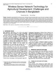
Generally speaking, the variation of the primary magnetic electromagnetic strength is correlated with the equivalent size, quality and material of a particle. The comprehensive mathematic model for inductive principle was reported for practical sensor use [46]. In recent years, a number of inductive sensors were proposed to detect ferrous and non-ferrous debris in lubricant [47-50]. A representative is Metalscan sensor developed by GASTOPS [51]. The sensors consists of three coils surrounding the inside bore. Two coils create a magnetic field and the third coil detects and disturbs in the field. Depending on the type and magnitude of the disturbance, the control unit determines the type of particle and the particle size. Metalscan has been claimed to be the first full flow wear debris sensor and thus has 100% detection efficiency. A more detailed comparison was carried out among different coils structures which could support the development of induction-based sensor [52]. In recent years, a multiple channel oil debris sensor based on inductive coulter counting principle was proposed as shown in Fig.3 [53]. Each sensing element is comprised of a two-layer planar coil and a micro-scale fluidic pipe crossing its center, which allows the sensor to process a large amount of lubricants without sacrificing the detection sensitivity. It claimed that a much higher throughput can be reached by using a large number of sensing channels to fulfill the needs for online oil monitoring.
Fig.3 Principle of inductive sensor with multiple channels [53]
Another inductive type sensor has been reported [54]. Likewise, a magnetic field in an air gap was adopted for depositing wear debris. The quantity of accumulated wear debris would change the magnetic flux between two magnet poles and thereby can be detected with a hall-effect sensor closely installed under the deposition gap. Comments: The common principle of inductive sensor can be generalized as the variation of magnetic field induced by metallic debris passing by. Compared with other reported principles, it can not only detect geometry parameters but also distinguish ferromatic and non-ferromatic debris, which makes it appealing in many applications. However, it still has some drawbacks depending on different conditions. The precision of inductive wear debris sensor is related to the coils wrapping form, magnetic flux strength generated by
WU Tonghai, et al.
particles, signal transducer and signal processing. Besides, such sensor is blind to morphological characteristics, compared with image sensors. Finally, such principles have a detection limit of wear debris size. 2.2.5 Electric sensors Electrical impedance and capacitive sensors are also widely adopted in wear debris detection. In this section, two typical principles including conductivity and capacitance are reviewed, respectively. 1)Conductivity-based principle The conductivity of metal debris is far better than that of lubricant. When mixed with metal debris, the resistance of lubricant will dramatically decrease. Consequently, by measuring the variation of resistance, the concentration of wear debris in oil is obtained. A representative practice, as illustrated in Fig.4 consists of a sensing resistor made of conductive film coated on a magnetic unit. When merged into oil, the sensing resistor will change its conductivity due to the attached wear debris on the surface of the conductive film. By measuring the variation of resistance, the amount of ferromagnetic wear debris is obtained [55]. An improved structure is reported consisting of a circular magnet, a goblet common electrode and eight electrodes. The wear debris falling into the gap between any two electrodes would be accumulated continuously until the two electrodes become conductive [56]. To eliminate the temperature effects, temperature compensation was designed in report [57].
Fig.4 Principle of improved conductivity wear debris sensor [55]
As reflected by the principle, the conductivity sensor performs well only in rough measurements. The sensor is blind to individual particle and other detailed information. 2)Capacitive-based principle Capacitive sensor, as widely adopted in oil quality monitoring [58, 59], is also popular in wear debris detection. Based on the physical difference of oil with and without wear debris, permittivity was adopted to detect overall wear debris as main contribution to oil contamination [19, 60]. Although some attempts were reported to identify a single wear particle [61], it still remains a difficulty task. A conductivity-based particle counter with a micro flow path was reported to be capable of counting wear particles. A micro flow path is designed
Sci China Tech Sci
to make a one by one pass for wear debris, and a plus signals will be detected when a wear debris is going through. The reported identification limit of particle diameter could be as small as 10~25 micron [62, 63]. 3)Static electricity-based principle Due to the physical nature of a metal material, metallic wear debris is charged electrically in friction. The static electricity carried by wear debris is related to friction conditions such as load, speed and surface roughness, etc. Recently, static electricity was utilized in wear monitoring [64-67]. The earliest report of static electricity-based sensors was in the wear particle monitoring of airway jet engines and internal gas turbines, with well-established correlation between the static electricity of wear debris and wear volume. One outstanding advantage of this technique is the identification of non-metal wear debris, e.g. ceramic particles. In addition, it detects fine particles and thus theoretically is suitable for monitoring early faults, especially in the aviation field [64, 67]. Its principle is illustrated as follows. Two electrostatic sensors have been installed along oil pipe. When wear debris passes through by the two sensors successively in different speed, the static electricity from each sensor is obtained. The mutation of the outputs of the two sensors represents the existance of wear debris in specific size. The apparent shortage of this sensor is its inaccuracy in the case when large quantity of wear debris passing simultaneously. In addition, it cannot identify materials. 2.2.6 Energy principle Two kinds of principles are categorized. First is based on the fluid pressure variation before and after a filter blocked by wear debris. Second is the wear volume variation of a metal film deposited on a ceramic substrate, which generally happens due to the erosion of debris in oil flow. Both of them have an energy attenuation to evaluate the cumulated volume of wear debris, and the accuracy is subject to flow rate and pressure, etc. 1)Indirect method Filters are generally adopted in lubrication systems to block various solids, and would inevitably cause the loss of systematic pressure and flow rate. By measuring the pressure loss and flow rate, the amount of wear debris blocked by filters is roughly reported. Accordingly, differential pressure principle based on single measurement before and after a filter was reported. However, even though a good work condition of the filter has been obtained, the type and size of wear debris cannot be obtained. To this end, an improved multi-measurement system was proposed [68]. Two filters with same pore size were used as a test screen filter and a reference screen filter, respectively. Thereby, two pressure, ΔPtest and ΔPref, can
WU Tonghai, et al.
be obtained. Two progresses are stressed: one is that general size of debris in each filter can be obtained by some algorithms with two pressure losses, and the other is that the influence of flow rate and temperature can be counterweighted by using two filtrations. In practice, most on-line or in-line oil sensors currently used in a lubricating oil line tend to be influenced by the flow rate or systematic pressure of the oil. Thus, the accommodation of many different flow rates and pressure is desired for improving the accuracy and reliability of such kind of sensors. A representative realization was reported that a pressure measure was integrated with a wear debris sensor to compensate the influence of temperature and flow rate [69]. 2)Direct method Considering the velocity of particles in oil, a thin film sensor to detect in-line wear debris was designed with energy principle [70]. The film could sense the bump of wear debris and thus the concentration is extracted from the accumulated kinetic energy. Such sensor was reported with purpose of on-line monitoring. However, the strict limitation was proposed on the flow rate, particle size and material, and up to date there is no successful application published. 2.2.7 Ultrasonic principle When particles pass through an ultrasonic wave field, the ultrasonic wave would be attenuated due to the effects of scattering and/or reflection. By measuring the amount of attenuation, the information of the size and quantity of wear debris is obtained [71]. One application in the contaminant monitoring of a hydraulic system shows that the ultrasonic wave could detect particles ranging from 30 to 1000 microns [72]. Similar to the aforementioned optical principle, there are two typical applications: scattering and reflecting sensor [73, 74]. Two face mounting ultrasonic transducers were adopted for scattering sensor, one for transmitting and another for receiving. Because ultrasonic wave could only be scatted by a solid particle, air bubble cannot be identified by this principle. Reflecting sensor adopted only one transducer which served as both transmitting and receiving units. One acoustic emission pulse would be responded with two echo pluses, one from suspending particle and the other from the wall. Markedly different magnitudes of two echo plus provided possibility to distinguish the information of wear debris. The advantage of the scattering principle over reflecting one is that it distinguishes air bubbles by their opposite phases due to their natural acoustic impedance [74]. By integrating scattering and reflecting principles, three kinds of contaminants including water drop, air bubble, and wear debris were distinguished [75]. Comments: ultrasonic sensor was reported to have
Sci China Tech Sci
additional merits, e.g. having a high resolution up to 3 micron of wear debris and being popular for on-line wear monitoring. Despite of some application limits in its installation, frequency and vibration, ultrasonic sensor shows potential prospect owing to its high accuracy and material identification ability. Comments for wear debris sensors The mentioned various sensor technologies make it possible to analyze the condition of lubricant in a different view, however, it should be noted that because sensors use different principles to determine the lubricant situation, their ability to detect specific oil faults vary as different monitoring methods and result interpretation. Appearances of multifarious expert system for on-line oil monitoring have proved the significance of information fusion—a promising area should be particularly paid attention to in the future. 2.3
Element sensor
Element concentration of oil and wear debris is critical information for state monitoring. Elemental analysis reveals wear sources by accurately measuring the element contents of metal or nonmetal debris at a molecular or atom scale, and thus diagnoses faults earlier. Naturally, spectroscopic strategies are the first preference with many options including Atomic Absorption Spectrometry (ABS), Inductively Coupled Plasma Atomic Emission Spectrometry (ICP-AES), X-ray fluorescence spectrometry (XRF), Photo-acoustic spectroscopy (PAS), IR (Infrared) and FTIR (Fourier transform infrared) spectrometry, etc. Unfortunately, most of the above principles have difficult to be transplanted into on-line sensors due to their complicated structure and analysis. Even so, distinguished progresses have been made on element sensors for on-line or in-line monitoring in the past decades and are presented as follows [76-78]. 2.3.1 Infrared (IR) and Fourier transform infrared (FTIR) spectrometry Although spectroscopic techniques may not be directly considered in the sensor category, they are important analytical tools for oil analysis. This analysis covers the detection of wear metal ions in engine oil, trace water contents, and determination of acidic components and others. IR provides quantitative information of organic molecular by absorbing principle. On-line IR sensor is adopted for inspection of oil quality, pollutant and additives. However, IR sensor cannot provide overall information content of all elements and data interpretation is time-consuming. In comparison to IR sensors, FTIR sensors have better potential for on-line analysis as taking the advantage of auto-commutating, which makes mathematically-intensive infrared data process more
WU Tonghai, et al.
convenient for auto analysis [76, 79, 80]. IR-sensor, however, cannot provide total information content in overall monitoring period [77]. In addition, the interpretation of the resultant data is labor intensive [78], which dramatically limits its popularity. FTIR sensor has been recommended to be a more versatile spectroscopic technique for analyzing antioxidant, water and acidic components in oxidized engine oil [81]. One of the representatives is the Oil Condition Monitor developed by Foster-Miller [78].
Sci China Tech Sci
that is detected with hyper sensitive microphones or piezoelectric devices.
2.3.2 XRF (X-ray fluorescence ) sensors X-ray fluorescence can be understood by comparison to AE spectrometric methods. XRF provides quantitative and type
Fig. 5 layout of a PAS sensor [84]
information of wear debris element. Some reports stated that such kind of sensors could detect the concentration ranging from 0 to 50 ppm, or even more than 250 ppm, of metal materials like copper and iron debris. XRF identifies and quantifies chemical elements in oil when it passing through a control cabinet. The targeted elements are excited by the X-rays and fluorescence photons transmitting through the flow cell window to the detector, which converts them into an analog output. The analog output is then converted into a scaled signal by the control electronics. The signal intensity is proportional to the concentration of the element. [82] Spectro Analytical Instruments Inc [83] has developed EDXRF technology for on-line elemental measurements of suspended particles for use in quality monitoring or process control. EDXRF technology allows the user to measure concentrations of 12 elements and up to six different elements at a time. The advantages of XRF technology are that it is nondestructive, noninvasive and it typically needs minimal services. An in-line XRF system has been developed at the Pacific Northwest National Laboratory (PNNL) for additional applications [78].
Accordingly, a range of monochromatic wavelengths has been used to analyze a sample. Since PAS analyzes the thermal waves that generate acoustic waves, unlike other types spectroscopy, it is unaffected by surface scattering effects. This allows the analysis of oils with suspended solid particles. Another potential development of PAS to be an online sensor is miniature. However, the accuracy of miniaturized devices for detecting the desired oil parameters has not been established yet.
2.3.3
Photo-acoustic Spectroscopy (PAS)
As illustrated in Fig.5, the basic principle of PAS is similar to that of IR spectroscopy [84]. The modulated light source, usually a high powered xenon or halogen lamp, passes through a monochromator to allow selection of the desired wavelength of light. The molecules become excited when absorbing particular wavelength. A series of thermal waves could be generated for each cycle of modulated light, and be transferred to the contacting gas as an acoustic wave. Individual and compounds chemicals and elements are identified with different absorption coefficients.
2.3.4 Fluorescence spectroscopy X-ray fluorescence spectrometry (XRF) has been applied for metal ions detection in oil. Both fine particles as well as plate metal samples has been measured. However, it is limited by the depth to what extent X-rays is effective. In the case of plate metal, a sample of one-half inch thickness will yield the same results as a thicker sample. This leads to a particle size effect although XRF produces large signals for large particles and small signals for small particles. There are numerous benefits to bring this technique on-site or even on-line for critical systems [85]. On-line systems with XRF, not yet available, would offer the advantage of continuous monitoring and protection. A high quality monitor like XRF is believed to provide best assessments of remaining useful life. Comments for element sensors Based on element principle, the aforementioned sensors are capable to provide fairly accurate results; nonetheless, complex structure and relatively expensive cost retard its further application as other sensors. Generally, with simplification of the structure and operation, these sensors are very promising to online oil condition monitoring. 2.4
PAS is considered to be a photo-thermal technique as light is absorbed by a sample, which causes a change in the thermal energy structure of molecules. The change can be observed by measuring the temperature or density of the sample. The cycle of energy absorption and emission results in a change in pressure, causing an acoustic wave
Trend of oil sensor technology
Imperative demands of on-line monitoring boost advancement of sensor technology. Increasing focuses were paid in development of new sensors. Over the past decades, various sensors have been reported and have become commercial available worldwide. With above
WU Tonghai, et al.
analysis on its current state, general trends of oil sensors is generalized into the following respects. 1)High accuracy Increasing high accuracy is always the pursuit of sensor technology. Aiming at more accurate diagnosis, collecting more detailed features is the objective for sensor development. Two aspects are concerned and they are precise quantity and detailed item. Taking wear debris for example, overall characteristics like concentration and equivalent size cannot meet the new requirements for determining wear mechanism and material. Color, shape and more detailed information were extracted from on-line images; ferro- and non-ferro materials have been identified from electrical signals, and even elements were extracted from on-line various spectrum techniques. 2)Integration Because of the complex nature and the interaction of oil proprieties, it is hard for any principle to obtain and distinguish all degradation factors. Correspondingly, highly integrated sensor combination is attracting more and more pursuits. An “on-line/in-line monitoring laboratory” is approaching. In another sense, integration means the collection and transmission of multi-source heterogeneous signals, like wear debris image and viscosity value. 3)Intelligence Self-integrated data analysis and diagnosis is another trend with focus on embedded microprocessor. As an effective solution to the multi-source heterogeneous signals mentioned above, intelligent unit provides uniform signal for transmission by a primary data processing with specialized methods. Temperature or pressure compensation is another kind of intelligent functions. 4)Reliability Two points are stressed when it comes to reliability. The first is the reliability of sensor to maintain its working condition in harsh environment, which is a dominant problem in on-line monitoring. And the second is the credibility of the collected data, which is popular due to high ratio of noise to signal. Comments: Sensor seems to be the hot spot of on-line monitoring. However some awareness still should be clear when pursing for more measurable physical quantities. What is the intrinsic relationship among these quantities and what is the physical relationship between quantities and tribological performances.
3. Applications and problems of on-line oil monitoring
Sci China Tech Sci
antifreeze contamination The three stages degradation of engine oil is classified as good, rapid increase of total acid number (TAN) and rapid increase of viscosity. The two latter stages have been detected via the on-line sensors in a road test. 3.2 Wind Turbine Gearboxes The gearboxes of wind turbine power generation units have been initially reported to be equipped with metalscan sensors [87]. Up to data, the technology introduction and condition indicator development for wind turbines have been constantly reported. Damage limit is adopted as a simple criteria to decide whether the gearbox is healthy or not, and if not, how much damage exists and how much longer the gearbox can be operated. Metalscan’s condition indicator has been developed to define reliably of the gearbox. 3.3
Aircraft engines
Successful application of the Metalscan has been reported in aircraft engines for oil monitoring. It has been first applied on the F119 engines of the USAF F22 Raptor advanced tactical fighter [87]. The typical layout of Metalscan sensor installation is shown in Fig.6 Over 300 aero-derivative engines worldwide are equipped with the Metalscan sensors and have accumulated well over 12 million hours of operation for the fleet, thus have become the industry standard for oil debris monitoring for high value rotating equipment.
Fig. 6 Typical layout of metalscan sensor installaton[87]
3.4 Shipping engines 3.1
Automotive engines
Application of new oil condition sensors was reported in vehicles [86]. The oil condition sensors installed in the oil pan are used for detecting water condensation and
An application of on-line wear condition monitoring system, detecting particle, lubricant quality and shaft torque moment and instantaneous rotation velocity, has been reported in marine diesel engines [88].
WU Tonghai, et al.
Sci China Tech Sci
Recently, an application of on-line oil debris monitoring system has been reported in a dredger engine, which is believed that it is more precise than existing methods for detecting the fault characteristics to the engine’s abnormal state [44]. Typical layout of on-line image sensor installation in ship is shown in Fig.7. Satisfied effects of wear mode identification are obtained accordingly.
(b) On-line wear debris images by the on-line monitor Fig.8 Application of on-line wear monitoring in a mine scraper conveyor reducer
4
Fig. 7 Typical layout of on-line image sensor installaton in ship[44]
The Metalscan has also been used in the leading cruise lines to fit to their vessels which use propulsion pods. It has reported that over 1,200 MW of installed propulsion power delivered through the ABB and Rolls Royce pod units have been installed with the Metalscan monitors [87]. 3.5 Mining Equipment Another application is the on-line oil monitoring system for a mine scraper conveyor reducer, as shown in Fig.8(a). An on-line oil monitoring system is set out of the gearbox with oil pipe connected with inner oil. The output images of wear debris are transmitted through a local network for real-time analysis as shown in Fig.8(b). However, its feasibility remains to be improved due to its oil sampling means from the tank. Fortunately, it is not far from the true sense of the on-line monitoring.
On-line oil sensor
(a) Mine scraper conveyor reducer with an oil monitor
Conclusion
On-line oil monitoring, was developed rapidly in the past decades because of its exclusive superiority in wear analysis and the increasing demand of CBM. It is becoming an independent technology of state monitoring. The successful application of on-line oil monitoring technology will beyond traditional diagnosis and prognosis, and will be extended to be the core technique for the digitalization of the life time performance of a machine. Correspondingly, the progresses have been reviewed systemically and extensively. Sensor developments and their industrial applications have been reviewed comprehensively and the potential future directions have been presented and discussed. Conclusions are drawn as follows: For sensor technology: many sensors based on various physical and chemical principles have been developed and used for detection and analysis of oil quality degradation, contamination, and wear debris concentration and elements. A trend aiming at accuracy and integration has been generalized for recent development. However, beyond the developed technology, the original intention seems to be ignored. Signal or couple indexes are much less important than the content of oil monitoring because the overall condition evaluation of lubricant, wear and working condition is the ultimate goal. However, very limited investigations were reported on the mechanisms about the true origins of degradation and the extent to which they influence the wear process, which is the base for the intention of new sensor development. For industrial application: Although limited industrial applications were reported, on-line oil monitoring technology is increasingly recognized and concerned. Several applications were found in important fields including aircraft, wind turbine and ship engine, etc. It is believed that the on-line oil monitoring is still in its infant stage for industrial application and experience is to be accumulated for its ultimate objective. Overall, sensor development has been receiving more
WU Tonghai, et al.
attention over the method investigation both for data interpretation and industry applications. Theoretical research on mechanism and methodology should be the next focus of work.
Sci China Tech Sci
19 20
21
Acknowledgement 22 This work was supported by the National Natural Science Foundation of China (Grant No. 51275381) and the Science and Technology Planning Project of Shaanxi Province, China (Grant No. 2012GY2-37). The author would also like to acknowledge my collaborators at the University of New South Wales for very helpful discussions. Special thanks to the China Scholarship Council. (Grant No. 201206285002).
References 1
2
3
4
5
6
7 8 9 10
11
12
13
14 15
16 17 18
Jardine A K S, Lin D, Banjevic D. A review on machinery diagnostics and prognostics implementing condition-based maintenance. J. Mechanical systems and signal processing, 2006, 20(7): 1483-1510 Agoston A, Ötsch C, Jakoby B. Viscosity sensors for engine oil condition monitoring-Application and interpretation of results. J. Sensors and Actuators A: Physical, 2005, 121(2): 327–332 Markova L V, Myshkin N K, Kong H, et al. On-line acoustic viscometry in oil condition monitoring. J. Tribology International, 2011, 44(9): 963-970 Hammond J M, Lec R M, Zhang X J, et al. An acoustic automotive engine oil quality sensor. In: Frequency Control Symposium, 1997, Proceedings of the 1997 IEEE International. IEEE, 1997: 72-80 Durdag K, Andle J. Real-time viscosity measurement for condition-based monitoring using solid-state viscosity sensor. J. Tribology Transactions, 2008, 51(3): 296-302 Bennett J W, Matsiev L, Uhrich M, et al. New solid state oil condition sensor for real time engine oil condition monitoring. J. Symyx Technologies Inc, 2005 Durdag K. Solid state acoustic wave sensors for real-time in-line measurement of oil viscosity. J. Sensor Review, 2008, 28(1):68-73 Billson D. Ultrasonic liquid viscosity sensor using mode conversion: WIPO Patent, 2005012897, 2005-2-11 Jakoby B, Scherer M, Buskies M, et al. An Automotive Engine Oil Viscosity Sensor. J. Sensors Journal, IEEE, 2003, 3(5): 562-568 Stoyanov P G, Grimes C A. A remote query magnetostrictive viscosity sensor. J. Sensors and Actuators A: Physical, 2000, 80(1): 8-14 Bravo-Imaz I, Garcia-Arribas A, Gorritxategi E, et al. Magnetoelastic Viscosity Sensor for On-Line Status Assessment of Lubricant Oils. J. Magnetics, IEEE Transactions on, 2013, 49(1): 113-116 Jain M K, Schmidt S, Grimes C A. Magneto-acoustic sensors for measurement of liquid temperature, viscosity and density. J. Applied Acoustic, 2001, 62(8):1001–1011. Lancaster J K. A review of the influence of environmental humidity and water on friction, lubrication and wear [J]. Tribology International, 1990, 23(6): 371-389 Smolenski D J, Schwartz S E. Automotive engine-oil condition monitoring[J]. Lubrication engineering, 1994, 50(9). Hammer E A, Tollefsen J, Olsvik K. Capacitance transducers for non-intrusive measurement of water in crude oil. J. Flow Measurement and instrumentation, 1989, 1(1): 51-58 Vaisala O. Method and apparatus for measuring water content. U.S. Patent, US6809528.B1,2004-10-26 Yasuhara S, Kobayashi H. Oil deterioration detector method and apparatus. U.S. Patent, 4646070, 1981-11-17 Dickert A D, Johnson E L, Kirkpatrick J F, et al. Oil monitor with magnetic field. U.S. Patent, 5262732, 1993-11-16
23
24
25
26
27
28
29
30 31 32
33
34
35
36
37
38
39
40
Raadnui S, Kleesuwan S. Low-cost condition monitoring sensor for used oil analysis. J. Wear, 2005, 259(7): 1502-1506 Schuller R B, Gundersen T, Halleraker M, et al. Measurement of water concentration in oil/water dispersions by a Single-electrode capacitance probe. J. Instrumentation and Measurement, IEEE Transactions on, 2004, 53(5): 1378-1383 Ma S Y. Development and application of a radio-frequency capacitive sensor. J. Journal of Transducer Technology, 2001, 20(2): 43-45 Sun K H, Yang X R, Liu L H, et al. The Principle and Design of Radiofrequency Capacitive Sensor. J. Journal of Transducer Technology, 1998, 9: 7-9 Turner J D, Austin L. Electrical techniques for monitoring the condition of lubrication oil. J. Measurement science and technology, 2003, 14(10): 1794 Jia C, Zhang F, Zhao X, et al. A Novel Electrochemical Impedance Spectroscopy Sensor for On-line Measurement of Water Content in oil. J. Lubrication Engineering, 2011, 5: 029 Smiechowski M F, Lvovich V F. Electrochemical monitoring of water-surfactant interactions in industrial lubricants. J. Journal of Electroanalytical Chemistry, 2002, 534(2): 171-180 Garcia-Golding F, Giallorenzo M, Moreno N, et al. Method and apparatus for determining the percentage water content of oil in water emulsion by specific admittance measurement. U.S. Patent, 5260667, 1993-11-9 Garcia-Golding F, Giallorenzo M, Moreno N, et al. Sensor for determining the water content of oil-in-water emulsion by specific admittance measurement. J. Sensors and Actuators A: Physical, 1995, 47(1): 337-341 Tollefsen J, hammer E A. Capacitance sensor design for reducing errors in phase concentration measurements. J. Flow Measurement and Instrumentation, 1998, 9(1): 25-32 Wylie S R, Shaw A, Al-Shamma'a A I. RF sensor for multiphase flow measurement through an oil pipeline [J]. Measurement Science and Technology, 2006, 17(8): 2141. Agar J. Method and apparatus for net oil measurement. U.S. Patent 4774680, 1988-9-27 Scott B N, Yang Y S. Microwave apparatus for measuring fluid mixtures. U.S. Patent 4862060, 1989-8-29 Blanco M, Coello J, Iturriaga H, et al. Determination of water in lubricating oils by mid-and near-infrared spectroscopy[J]. Microchimica Acta, 1998, 128(3-4): 235-239 Zhang Y, Jiang L, Wu D, et al. Non-Invasive Measurement of Water Content in Engine Lubricant Using Visible and Near Infrared Spectroscopy. J. Spectroscopy and Spectral Analysis, 2010, 30(8): 2111-2114 Klotzbucher T, Holzki M. Evanescent-field fiber sensor for the water content in lubricating oils with sensitivity increase by dielectrophoresis. J. 2012 Foster N S, Amonette J E, Autrey T, et al. Detection of trace levels of waters in oil by photoacoustic spectroscopy. J. Sensors and Actuators B: Chemical, 2001, 77(3):620-624 Mujahid A, Dickert F L. Monitoring automotive oil degradation: analytical tools and onboard sensing technologies. J. Analytical and bioanalytical chemistry, 2012, 404(4): 1197-1209 Wang SS, Lee A, Mamrick M S. An electrochemical technique for evaluating electrical contact lubricants. In: Proc. Thirty-Third IEEE Holm Conf., Electrical Contacts. 1987 Wang S S. A sensor for glycol contamination in oil. Extended abstract no. 692, fall meeting of the Electrochemical Society, Toronto, 1992 Wang S S, Lee H S. An electrochemical sensor for distinguishing two-stroke-engine oils. J. Sensors and Actuators B: Chemical, 1997, 40(2): 199–203 KarisAllen K J. Literature Review of the State of the Art for Graphical User Interfaces (GUI) for a Series of Oil Quality Monitoring Sensors for Shipboard Equipment[R]. FACTS ENGINEERING INC HALIFAX (NOVA SCOTIA), 2011..
WU Tonghai, et al.
41
42
43
44 45
46
47
48
49
50 51
52
53
54 55 56 57 58
59
60
61
62
63
64
Kwon O K, Kong H S, Han, H G, et al. On-line measurement of contaminant level in lubricating oil. U.S. Patent, 6151108, 2000-11-21 Hunt T M. Handbook of Wear Debris Analysis and Particle Detection in Liquids. 1st ed. Elsevier Applied Science: New York 1993 Kuo W F, Chiou Y C, Lee R T. Fundamental characteristics of wear particle deposition measurement by an improved on-line ferrographic analyzer. J. Wear, 1997, 208(1): 42-49 Wu T H, Mao J H, Wang J T, et al. A New On-Line Visual Ferrograph. J. Tribology transactions, 2009, 52(5): 623-631 Wu T H, Wang J Q, Peng Y P, et al. Description of wear debris from on-line Ferrograph image by their statistical color. Tribigology & Lubricaiton Techology, 2012, 68(11): 69-77 Han L, Hong W, Wang S. The key points of inductive wear debris sensor. Fluid Power and Mechatronics(FPM), 2011 International Conference on. IEEE, 2011: 809-815 Hong B F, Ying T Z, Guo Q R, et al. Study on Oil Detection Technology Based on Inductive Wear Debris Sensor. Electronic Measurement & Instruments, 2009. ICEMI’09. 9th International Conference on. IEEE, 2009: 2-810-2-813 Du L, Zhe J, Carletta J, et al. Real-time monitoring of wear debris in lubrication oil using a microfluidic inductive Coulter counting device. J. Microfluidics and nanofluidics, 2010, 9(6): 1241-1245 Miller J L, Kitaljevich D. In-line Oil Debris Monitor for Aircraft Engine Condition Assessment. Aerospace Conference Proceedings, IEEE, 2000, 6: 49-56 Du L, Zhe J. A high throughput inductive pulse sensor for online oil debris monitoring. J. Tribology International, 2011, 44(2): 175-179 Kitaljevich D, Dupuis R, Cassidy K. Oil debris monitoring for helicopter drivetrain condition based maintenance in [J]. American Helicopter Society International Condition Based Maintenance Specialists Meeting2008, 2008: 163-180 He X, Yang D, Hu Z, et al. Theoretic analysis and numerical simulation of the output characteristic of multilayer inductive wear debris sensor. Prognostics and System Health Management (PHM), 2012 IEEE Congerence on. IEEE, 2012: 1-4 Du L, Zhe J. Parallel sensing of metallic wear debris in lubricants using undersampling data processing. J. Tribology International, 2012, 53: 28-34 Chiou Y C, Lee R T, Tsai C Y. An on-line Hall-effect device for monitoring wear particle in oils. J. Wear, 1998, 223(1): 44-49 Itomi S, Shoji. Oil check sensor. Japanese Patent 2002286697, 2002-10-3 Itomi S. Oil condition sensor. U.S. Patent, 7151383, 2006-12-19 Itomi S. Oil condition sensor. U.S. Patent, 7112973, 2006-9-26 Ka d en H, Fi cht ner D P W, Ahlb orn D C K. Se n sorik zu r O nl i n e -M e ssu n g vo n S c h mi er o l e i g e n sc ha ft e n . J. MT Z-Motortechnisch e Zeitschrift, 200 0, 61(3): 16 4 -170 Appleby M, Choy F K, Du L, et al. Oil debris and viscosity monitoring using ultrasonic and capacitance/inductance measurements[J]. Lubrication Science, 2013: DOI:10.1002/ls.1221. Ding X Y, Zheng H, Jian W X. Research on Capacitive Sensor for Online Oil Monitoring. Prognostics and System Health Management Conference (PHM-Shenzhen), 2011. IEEE, 2011: 1-4 Sohn L L, Saleh O A, Facer G R, et al. Capacitance cytometry: Measuring biological cells one by one. J. Proceedings of the National Academy of Sciences, 2000, 97(20): 10687-10690 Murali S, Xia X, Jagtiani A V, et al. Capacitive coulter counting: detection of metal wear particles in lubricant using a microfluidic device. J. Smart Materials and Structures, 2009, 18(3): 037001 Zhe J, Du L, Carletta J E, et al. Metal wear detection apparatus and method employing microfluidic electronic device. U.S. Patent, 20100109686, 2010-5-6. Powrie H. Use of Electrostatic technology for aero engine oil system monitoring. Aerospace Conference Proceedings, 2000 IEEE. IEEE, 2000, 6: 57-72
Sci China Tech Sci
65 66
67
68
69 70
71 72
73 74
75
76 77 78
79 80
81 82 83
84
85
86 87 88
Fisher C E, Forfitt R. System and method for monitoring debris in a fluid. U.S. Patent, 5760298, 1998-6-2 Harvey T J, Morris S, Wang L, et al. Real-time monitoring of wear debris using electrostatic sensing techniques. J. Proceedings of the Institution of Mechanical Engineers, Part J: Journal of Engineering Tribology, 2007, 221(1): 27-40 Harvey T J, Wood R J K, Powrie H E G. Electrostatic wear monitoring of rolling element bearing. J. Wear, 2007, 263(7): 1492-1501 Brown N K, Friedersdorf F J. System and method to detect particulate debris in a fluid. U.S. Patent Application, 20100192679, 2010-8-5 Nikkels R R, Summers S K. Metal particle sensor system. U.S. Patent, 2007209427, 2007-9-13 Santilli R. The Fulmer Method of Monitoring Fluid Abrasivity as an Indication of Fluid Condition and Machine Health. COMADEM 89 International. Springer US, 1989: 55-67 Flax L, Gaunaurd G C, Uberall H. Theory of Resonant Scattering. J. Physical Acoustics, 1981, 15: 191-294 Harries C J, Sayles R S, Macpherson P B. Research into an on-line device for monitoring contamination in fluids using ultrasonic techniques. J. Final Report Imperial Coll of Science and Technology, London (England). Tribology Section, 1984, 1 Miller J G, Clark R E, Conradi M S, et al. Ultrasonic continuous wave particle monitor. U.S. Patent, 4015464, 1977-4-5 Edmonds J, Resner M S, Shkarlet K. Detection of precursor wear debris in lubrication systems. Aerospace Conference Proceedings, IEEE , 2000, 6: 73-77 Nemarich C P, Whitesel H K, Sarkady A. On-line wear-particle monitoring based on ultrasonic detection and discrimination. David Taylor Research Center Bethesda MD Propulsion and Auxiliary Systems Dept, 1988 Kristiansen P, Leeker R. US Navy’s In-Line Oil Analysis Program. J. Lubr. Fluid Power J, 2001, 3: 3-12 Coates J P, Setti L C. Condition monitoring of crankcase oils using computer aided infrared spectroscopy. 1983 van de Voort F R, Sedman J, Pinchuk D. An Overview of Progress and New Developments in FTIR Lubricant Condition Monitoring Methodology [J]. Journal of ASTM International, 2011, 8(5). Toms A, Toms L. Oil analysis and condition monitoring. Chemistry and Technology of Lubricants. Springer Netherlands, 2010: 459-495 Scherer M, Arndt M, Bertrand P, et al. Fluid condition monitoring sensor for diesel engine control. Sensors, 2004. Proceedings of IEEE. IEEE, 2004: 459-462 Adams M J, Romeo M J, Rawson P. FTIR analysis and monitoring of synthetic aviation engine oils. J. Talanta, 2007, 73(4): 629-634 Pieper K A, Taylor I J. In-Line Wear Mnitor. General motors corp indianapolis in Allison gas turbine DIV, 1989 Sabrin G, On-line and In-line Wear Debris Detectors: What's Out There? [OL]. Practicing Oil Analysis /Machinery Lubrication, [2003-9] http://www.machinerylubrication.com/Read/521/in-line-wear-debris -detectors. Koskinen V, Fonsen J, Kauppinen J, et al. Extremely sensitive trace gas analysis with modern photoacoustic spectroscopy. J. Vibrational spectroscopy, 2006, 42(2): 239-242 Gary H, Robert W, Darrell C, X-Ray Fluorescence Spectroscopy -The Next Generation of Wear Debris Analysis [OL]. Practicing Oil Analysis /Machinery Lubrication, [1998-11]. http://www. Machinerylubrication.com/Read/86/x-ray-fluorescence-spectroscopy Wang S S. Road tests of oil condition sensor and sensing technique。 J. Sensors and Actuators B: Chemical, 2001, 73(2): 106-111 Leske S, Kitaljevich D. Managing gearbox failure, Dewek[J]. Dewi Magazine, 2006 (29) Liu Y, Liu Z, Xie Y, et al. Research on an on-line wear condition monitoring system for marine diesel engine. J. Tribology International, 2000, 33(12): 829-835


![Emerging Technology Trend - NEOnet [PDF]](https://m.moam.info/img/260x300/emerging-technology-trend-neonet-pdf_6479f191098a9ee0288b460d.jpg)