process, we have performed measurements of the current flow in the bath, ILIP, vs. the voltage of the ... Fraunhofer ISE: one for copper, one for silver plating. The.
PROGRESS IN ADVANCED METALLIZATION TECHNOLOGY AT FRAUNHOFER ISE S. W. Glunz, M. Aleman, J. Bartsch, N. Bay, K. Bayer, R. Bergander, A. Filipovic, S. Greil, A. Grohe, 1 2 M. Hörteis, A. Knorz, M. Menkö, A. Mette , D. Pysch, V. Radtke, P. Richter , D. Rudolph, T. Rublack, 3 C. Schetter, D. Schmidt, O. Schultz , R. Woehl Fraunhofer Institute for Solar Energy Systems (ISE), Heidenhofstr. 2, D-79110 Freiburg, Germany 1 2 3 now with Q-Cells AG, now with SolarWorld, now with Solexel
ABSTRACT
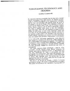
LIGHT-INDUCED PLATING Light-induced plating is an elegant technique to thicken a seed layer on the front side of a solar cell [1]. The operation principle is sketched in Fig. 1. The solar cell (right) and the silver anode (left) are located in an electrolytic bath. The back surface of the solar cell is connected to a protective potential with respect to the silver anode. By illuminating the solar cell, an additional negative voltage is generated at the front-surface contact grid, so that positive silver ions are deposited here and thicken the contact grid. A comprehensive overview of the historical development of this technology is given in Ref. [2]. Using light-induced plating to thicken screen-printed contacts on cell structures featuring a screen-printed AlBSF or a dielectric rear passivation has resulted in very high efficiencies up to 18.7% and 19.3%, respectively [3]. In order to achieve a better understanding of the electrochemical process, we have performed measurements of the current flow in the bath, ILIP, vs. the voltage of the solar cell, V2, at different illumination densities [2] (see Fig. 2).
V3 ILIP
V2 V1 Ag + Ag +
Ag -anode Fig. 1 Operation principle of light-induced plating. It can be clearly seen that the deposition current ILIP is dominated by the IV characteristics of the solar cell. Only for higher illumination densities the current is limited by the bath itself. 200 180
Current limited by bath
Suns 0.3 0.1 0.06 0.03 0.01
160 140
current [mA]
Fraunhofer ISE’s concept for an advanced metallization of silicon solar cells is based on a two-step process: the deposition of a seed layer to form a mechanical and electrical contact and the subsequent thickening of this seed layer by a plating step, preferably by light-induced plating (LIP). The concept of a multi-layer metallization is used for most of the relevant high-efficiency cell types in industry. The main advantage of this concept is that each layer can be optimized individually, i.e. the seed layer to achieve an optimal electrical and mechanical contact and the plated layer in terms of high lateral conductivity and good solderability. Solar cells results with seed layers fabricated by aerosol printing, chemical Ni plating on cells with a laser-structured dielectric layer and laser-enhanced Ni plating are presented.
120 100 80 60 40 20 0 -100
0
100
200
300
400
500
600
Voltage [mV] Fig. 2 IV characteristic of light-induced plating under different illumination densities (ILIP vs V2, see Fig.1 ). The process of light-induced plating is considerably simpler to implement industrially than direct contacting of the fine front-surface contact grid. Due to the increasing demand for high-efficiency process technology, this
technique was recently transferred to an industrial inline machine by company Gebr. Schmid. Two of these industrial inline machines are available at Fraunhofer ISE: one for copper, one for silver plating. The main focus of the current research is to increase the electrochemical understanding of the process and to further optimize the deposition quality in terms of lateral conductivity and contact geometry [4].
SEED LAYER FORMATION BY AEROSOL JETTING Currently the most promising processes to create a seed layer are jet printing and Ni plating (see next section). Jet-printed seed layers are created in a similar procedure as standard screen-printing including printing of metal pastes and firing through the front passivation layer [5]. However, mechanical stress on the substrate is avoided and much thinner lines down to 30 µm can be achieved. In order to avoid clogging of the nozzle when using a metal ink consisting of particles, it is necessary to use a 3 special printing head as the Optomec M D system. In this printing head the aerosol is wrapped up in a laminar gas flow which avoids the contact between metal aerosol and tip (see Fig. 3). The aerosol is focused by this sheath gas flow and line widths considerably smaller than the tip diameter can be achieved [6]. Thus, using a tip with a diameter of 150 µm it is possible to print lines with width below 30 µm.
Fig. 4 Cross section of an aerosol printed, fired and plated contact finger [6]. Due to the reduced contact area the requirements in terms of contact resistance and mechanical adhesion are much higher than in the case of screen-printing with a contact width of more than 100 µm. Thus, we have performed comprehensive studies on the contact properties of seed layers [8]. Especially the influence of the emitter sheet resistivity [9] and the height of the seed layer [10] was analyzed. For this study we have used padprinted fingers. Although the deposition method is different, the contact formation can be assumed to be similar. It is well known that the density of silver crystallites at the contact interface is a good indicator for the electrical contact quality [11]. Thus, for a microscopical analysis we have etched the contacts after firing and counted the crystallite imprints. In a first experiment the influence of the seed layer height was investigated (see Fig. 5). The crystallite density decreases strongly with decreasing seed layer height. This shows that a certain seed layer height is necessary to obtain good contact properties.
2
Crystallite Density (1/µm )
0.5
Fig. 3 Printing head of the aerosol jet technique [6]. After firing, the seed layers are thickened using lightinduced plating. A typical geometry of a plated contact finger is shown in Fig. 4. About 20 µm of silver is plated on top of the seed layer. The height of the seed layer is about 1.5 µm. Due to the roundish shape of the resulting finger incoming light can be reflected from the finger onto the active solar cell area. Thus, the optical width of the contact can be considerably smaller than the geometrical width which decreases the shadowing losses significantly. In fact in a recent work we have found that the optical width of an aerosol-printed and plated contact embedded in a module is only 43% of its geometrical width [7].
0.4 0.3 0.2 0.1 0.0
0
1
2
3
4
5
6
7
8
9
10
Seed Layer Height (µm) Fig. 5 Crystallite density as a function of the height of pad-printed seed layers.
Fig. 6 shows SEM pictures of a finger imprint on nemitters having a sheet resistance of 40 (top) and 90 Ω/sq (bottom) [9]. The ratio of SiNx covered to opened silicon area is comparable for both sheet resistances. However, the crystallite density is much higher for the 40 Ω/sq emitter resulting in a lower contact resistance.
NI-PLATING In the case of chemical Ni plating, the dielectric layer on the front surface has to be opened before metal deposition. This can performed e.g using a masking and etching or laser ablation step [12]. The results presented in this section were achieved using laser ablation. Although laser ablation is a very elegant and stress-free process, it is important to control the process parameters very carefully so that no laser damage is introduced into the sensitive space charge region [15].
40 Ω/sq
Fig. 7 Two-step process to form a Ni seed layer.
90 Ω/sq Fig. 6 Crystallite densities at the contact interface on cells with 40 and 90 Ω/sq. emitters [9].
After the laser step the Ni seed layer is deposited by an electro-less plating step and a low-temperature anneal. Accurate control of this process is crucial to avoid damage due to Ni diffusion into the space charge region [16]. As for the laser process this is quite a delicate task since we are using cells with shallow emitters (xj ≈ 0.2 -0.3 µm) and no additional deep diffusion under the contacts. After the formation of the seed layer the contacts are plated using the LIP process. Fig. 8 shows a finished contact finger on a textured monocrystalline cell.
These results show that the contact formation of very narrow and shallow contact seed layers on high-efficiency emitters with a high sheet resistance is quite a challenging task. On the other hand using the seed and growth technology it is possible to optimize the ink just for ideal contact properties while the lateral conductivity is obtained by the plated layer. In fact using modified inks it was possible to obtain excellent fill factors and efficiencies on both mono and multicrystalline silicon (see Tab.1). Table 1 Solar cell results using aerosol printing and an industrial cell structure (SiNx-front passivation, POClEmitter, Cz-Si, printed Al-BSF) Material A 2 [cm ]
Voc [mV]
Jsc FF 2 [mA/cm ] [%]
η
Cz-Si
12.5 x12.5
624
36.1
81.0
18.3
Multi-Si
15.6 x15.6
621
34.0
78.9
16.7
[%] Fig. 8 SEM image of a contact finger after nickel and silver plating [12].
Using this technology we have fabricated contacts on cell precursors with an industrial cell structure (see Tab. 2).
REFERENCES [1]
Table 2 Solar cell results using laser ablation and Ni plating and an industrial cell structure (SiNx-front passivation, POCl-Emitter, Cz-Si, printed Al-BSF). Material A 2 [cm ]
Voc [mV]
Jsc 2 [mA/cm ]
FF [%]
η
Cz-Si
620
34.6
77.4
16.6
5x5
[%]
The results show quite impressively that it is possible to contact solar cells with a shallow emitter without significant damage to the pn-junction. A detailed discussion of these results will be given elsewhere [13]. Obviously it would be very elegant to combine the laser and Ni plating in one process step. In fact we have already performed experiments using a set-up as shown in Fig. 9.
[2] [3]
[4] [5]
Laser [6]
[7] [8]
Ni seed Ni solution Fig. 9 Laser-enhanced Ni deposition.
[9] [10]
The laser opens the SiNx dielectric layer and activates the Ni deposition at the same time. Although this technology is still in an early stage, we have already achieved efficiencies up to 13.4% on industrial cell structures [14].
[11]
CONCLUSION
[12]
A two-step process for the metallization of solar cells increases the efficiency potential significantly. Using industrial feasible technologies as light-induced plating, aerosol printing and electro-less Ni plating very high efficiencies on industrial cell structures could be obtained. Due to the very narrow contact lines which are in the range of less than 50 µm the contact properties are crucial for a good cell performance. Acknowledgements The authors would like to thank S. Seitz, T. Leimenstoll and A. Herbolzheimer for processing and E. Schäffer for measurements. This work has been supported by the German Federal Ministry for the Environment, Nature Conservation and Nuclear Safety (BMU) under contract no. 0327569A.
[13] [14] [15] [16]
A. Mette, C. Schetter, D. Wissen, S. Lust, S. W. Glunz, and G. Willeke, "Increasing the efficiency of screen-printed silicon solar cells by light-induced silver plating", 4th World Conference on Photovoltaic Energy Conversion (Waikoloa, Hawaii, USA), pp. 1056-1059, 2006. A. Mette, Dissertation Thesis, Universität Freiburg, 2007. O. Schultz, A. Mette, M. Hermle, and S. W. Glunz, "Thermal oxidation for crystalline silicon solar cells exceeding 19% efficiency applying industrial process technology", Progress in Photovoltaics: Research and Applications, p. 317, 2007. J. Bartsch et al., 23rd European Photovoltaic Solar Energy Conference (Valencia), 2008. A. Mette, P. L. Richter, M. Hörteis, and S. W. Glunz, "Metal aerosol jet printing for solar cell metallization", Progress in Photovoltaics: Research and Applications, vol. 115, pp. 621-627, 2007. M. Hörteis, A. Mette, P. L. Richter, F. Fidorra, and S. W. Glunz, "Further progress in metal aerosol jet printing for front side metallization of silicon solar cells", 22nd European Photovoltaic Solar Energy Conference (Milan, Italy), pp. 1039-1042, 2007. R. Woehl et al., 23rd European Photovoltaic Solar Energy Conference (Valencia), 2008. A. Mette, A. Filipovic, M. Hörteis, O. Schultz, D. Pysch, P. L. Richter, C. Schetter, and S. W. Glunz, "Advanced metallization for crystalline silicon solar cells", 17th Workshop on Crystalline Silicon Solar Cells (Vail), pp. 104, 2007. D. Pysch, submitted to Progr. in Photovoltaics, 2008. D. Pysch, A. Mette, A. Filipovic, and S. W. Glunz, "Detailed analysis of fine line printed and planted solar cell contacts", 22nd European Photovoltaic Solar Energy Conference (Milan, Italy), pp. 12381243, 2007. G. Schubert, Dissertation Thesis, Universität Konstanz, 2006. M. Aleman, N. Bay, A. Grohe, A. Knorz, and S. W. Glunz, "Alternatives to screen printing for the front side metallization of silicon solar cells", 15th International Photovoltaic Science & Engineering Conference (Fukuoka, Japan), 2007. M. Aleman, publication under preparation, 2008. D. Rudolph et al., 23rd European Photovoltaic Solar Energy Conference (Valencia), 2008. A. Knorz et al., submitted to Progress in Photovoltaics. M. Alemán, N. Bay, M. Fabritius, and S. W. Glunz, "Characterization of electroless nickel plating on silicon solar cells for the front side metallization", 22nd European Photovoltaic Solar Energy Conference (Milan), p. 1590, 2007.