UCRL-PROC-215874
Progress in Three-Dimensional Coherent X-Ray Diffraction Imaging S. Marchesini,1, 2, ∗ H. N. Chapman,1, 2 A. Barty,1 A. Noy,1 S. P. Hau-Riege,1 J. H. Kinney,1 C. Cui,3 M. R. Howells,3 R. Rosen,3 J. C. H. Spence,4 U. Weierstall,4 D. Shapiro,2 T. Beetz,5 C. Jacobsen,5 E. Lima,5 A. M. Minor,6 and H. He6
arXiv:physics/0510032v2 [physics.optics] 6 Oct 2005
1
University of California, Lawrence Livermore National Laboratory, 7000 East Ave., Livermore, CA 94550, USA 2 Center for Biophotonics Science and Technology, UC Davis, 2700 Stockton Blvd., Ste 1400, Sacramento CA, USA 3 Advanced Light Source, Lawrence Berkeley National Laboratory, 1 Cyclotron Road, Berkeley, CA 94720, USA 4 Department of Physics and Astronomy, Arizona State University, Tempe, AZ 85287-1504, USA 5 Department of Physics and Astronomy, Stony Brook University, Stony Brook, NY 11794-3800, USA 6 National Center for Electron Microscopy, Lawrence Berkeley National Laboratory, 1 Cyclotron Rd, Berkeley, CA 94720, USA The Fourier inversion of phased coherent diffraction patterns offers images without the resolution and depth-of-focus limitations of lens-based tomographic systems. We report on our recent experimental images inverted using recent developments in phase retrieval algorithms, and summarize efforts that led to these accomplishments. These include ab-initio reconstruction of a two-dimensional test pattern, infinite depth of focus image of a thick object, and its high-resolution (∼ 10 nm resolution) three-dimensional image. Developments on the structural imaging of low density aerogel samples are discussed. Keywords: Coherent diffraction, X-ray microscopy, Phase retrieval, Lensless Imaging
I.
INTRODUCTION
In the last five years or so several new ideas have combined to provide us with a working solution to the phase problem for non-periodic objects. This capability opens exciting possibilities for using coherent x-ray diffraction microscopy (CXDM) for 3D imaging of fewmicron-sized objects at resolution levels previously inaccessible to x-ray microscopy. Since the first proof of principle demonstration of CXDM1 , a number of groups have been working to bring these possibilities into reality. Recent estimates2 of the dose and flux requirements of such measurements, indicate that attractive resolution values (about 10 nm for life science and 2–4 nm for material science) should be possible with reasonable exposure times using modern synchrotron-radiation sources. Thus CXDM promises a 3D resolution limited only by radiation damage, the collection solid angle and the number of x-rays collected. We therefore expect to have an advantage over lens-based tomography schemes that are currently limited in resolution and efficiency by the lens fabrication technology and, in principle, by the depth of focus effect. This capability provides an extremely valuable tool for understanding nanoscience, such as the study of minimum energy pathways for crack propagation in brittle solids, and characterizing the internal structure of mesoporous structures that are synthesized for a wide range of applications. In this paper we review the historical developments which have led to these opportunities and describe some of the activities of our multi-institutional collaboration, working at beam line 9.0.1 at the Advanced Light Source at the Lawrence Berkeley National Laboratory. In particular we will describe here two experiments, which demonstrate spectacular 3D imaging at 10 nm resolution. The portion of the work devoted to life-science imaging,
largely by the Stony Brook group, has been reported in these proceedings by Lima.3
II.
CONCEPTUAL HISTORY
The observation by Sayre in 19524 that Bragg diffraction under-samples the diffracted intensity pattern was important and led to more specific proposals by the same author for X-ray diffractive imaging of non-periodic objects.5 These ideas, combined with the rapid development of computational phase retrieval in the wider optics community especially the “support constraint”6,7,8 , enabled the first successful use of CXDM. An important review, which attempted to integrate the approaches of the optical and crystallographic communities, appeared in 1990.9 The connection was made between the ”solventflattening” or ”density-modification” techniques of crystallography and the compact support requirements of the hybrid input-output (HIO) algorithm. The importance of fine sampling of the intensity of the measured diffraction pattern was recognised at an early stage10 and has led to the method being referred to as ”oversampling”, since the Shannon sampling interval is half the Bragg interval in each dimension. The result of Shannon sampling the intensity is that the diffracted phased amplitude is at least two-fold oversampled in each dimension, which implies that the object obtained by transformation of an exactly-known amplitude function will be surrounded by a zero-padded region of at least three times the object area for 2D reconstructions, or at least seven times the object volume for 3D reconstructions. Such zero padding is a necessary concomitant of the use of a support constraint, although it is sufficient to oversample at less than the factor of two per dimension11 . The use of the support constraint as a means to phase the diffraction pattern is
2 now very widespread in the growing CXDM community.
FIG. 2: Scanning Electron Microscopy (SEM) of a silicon nitride pyramid (right) and the gold balls deposited on the hollow side of the membrane (left). Scalebar is 1 µm.
FIG. 1: SEM images of gold ball clusters (left) and reconstructed soft X-ray image (right) recorded at λ = 2 nm.18
III.
EXPERIMENTS WITH X-RAYS
In spite of the promise shown in simulations, the above theoretical advances were not accompanied by immediate experimental progress in the practical application of phase retrieval. The first successful X-ray technique was developed by the Stony Brook group at the X1 undulator beam line at the National Synchrotron Light Source at Brookhaven. The fruit of this effort, reported by Miao, Charalambous, Kirz and Sayre in 1999,1 was the first inversion of an experimental X-ray diffraction pattern to an image of a non-periodic object at 75 nm resolution. This success proved to be the beginning of a significant expansion in interest in CXDI in the US. In the last few years CXDM activities in the US has involved four groups which have all made contributions to the XRM 2005 conference: Stony Brook/Brookhaven, University of California at Los Angeles (UCLA), University of Illinois / Argonne, and ourselves at University of Arizona / Livermore Lab / Berkeley Lab. Stony Brook / Brookhaven have constructed a sophisticated experimental station for tomographic imaging of life-science specimens at cryogenic temperatures.12 This apparatus is now installed at ALS beam line 9.0.113 and serves all of the groups doing CXDM at the ALS. Robinson and coworkers at the University of Illinois have applied the principles of CXDM to hard x-ray experiments on microcrystalline particles, the density variations of which produce a diffraction pattern centered on each Bragg spot. The pattern can be reconstructed in 2D14 or scanned in 3D by very slight rotation of the crystal to give the equivalent of a tilt series. Such data have been reconstructed tomographically to produce a 3D image at 80 nm resolution.15 Miao (now at UCLA) and coworkers have made considerable progress in pushing the CXDI method to higher resolution in 2D (7 nm), higher x-ray energies and to
a limited form of 3D.16 They have also made the first application of CXDM to a biological sample.17 Our own efforts in this area have concentrated on retrieving phase based on the diffraction data alone18 , three dimensional ab-initio reconstruction of a test 3D object made of 50 nm gold balls deposited on a pyramid shaped silicon nitrade membrane at 10 nm resolution,19 two dimensional images with infinite depth of focus, and the imaging of materials sciences samples such as Ta2 O5 aerogel foams.
IV.
EXPERIMENTAL RESULTS
Our experiments reported here were carried out using the abovementioned Stony Brook University diffrac-
FIG. 3: (a) Reconstruction from a single view diffraction pattern at an object orientation ϕ = 24◦ . Scalebar is 1 µm. (b) Infinite depth of focus projection images, for the object orientation ϕ = 0◦ . (c) 2D section of the three dimensional diffraction pattern: as the object is rotated, the recorded Ewald spheres intercept the plane leaving some gaps of missing data.
3 tion apparatus, as well as an earlier apparatus20 . In the Stony Brook apparatus we carried out experiments using 750 eV (1.65 nm wavelength) X-rays that were selected from the undulator spectrum by a zone-plate monochromator with a spectral resolution of λ/∆λ=1000. The 4-µm-diameter monochromator exit pinhole also selects a transversely spatially coherent patch of the beam. The sample was located 20 mm from this pinhole. A directdetection bare CCD detector, with 20 µm pixel spacing, 1340×1300 pixels, was located 142 mm behind the sample. At these CCD and wavelength settings we have an object sampling interval in x and y of ∆x = 9.8 nm (in the small-angle approximation) and a field width of w = N ∆x= 11.7 µm. A beam-stop blocks the direct undiffracted beam from impinging on the CCD. More details are given by Beetz et al.12 . Diffraction patterns were collected with the sample oriented at rotation angles φ of -60◦ to +60◦ , at 1◦ intervals. Total exposure time was about 3 hours per sample. Test samples were made by placing a droplet of solution containing unconjugated colloidal gold balls on a silicon nitride membrane (thickness 100 nm) and allowing it to dry. A two dimensional object was imaged without prior knowledge about its shape by periodically updating the support region based on the current object estimate (Fig. 1)18 . A three-dimensional test sample was produced by placing a droplet of colloidal gold solution on a threedimensional silicon nitride pyramid-shaped membrane.19 This drop quickly evaporated and left the gold balls in a characteristic pattern where the gold tended to fill in the edges of the pyramid. An SEM image of the object is shown in Fig. 2. The pyramid base width is 2.5 µm and the height (base to apex) is 1.8 µm. An earlier, larger, silicon nitride pyramid object is shown on the right side of Fig. 2. Two dimensional projection images may be recovered from the diffraction intensities without having to first undergo a full 3D reconstruction, and we found this is a useful step to quickly examine our 3D datasets. The diffraction intensities from a single sample orientation are recorded on the Ewald sphere and will have the same depth of focus as a microscope with NA equivalent to the solid angle intercepted by the CCD. For our experimental parameters, giving NA = 0.084, we have a depth of focus of 120 nm, which is considerably smaller than the 1.8 µm thickness of the pyramid object. A reconstructed image, from a single-view diffraction pattern is shown in Fig. 3(a). Artifacts due to defocus are clearly seen in the image. By the choice of the parabolic term of the retreived phases23 the plane of focus can be numerically scanned throughout the depth of the object. By sectioning the three dimensional Fourier space with a sphere of larger radius than the Ewald surface, we can increase the depth of focus. Infinite depth-of-focus twodimensional projection images were obtained (Fig 3b) from a plane in reciprocal space perpendicular to the projection direction (Fig. 3c)19 .
FIG. 4: Three dimensional diffraction pattern (left) (with a quadrant removed for visualization) and reconstructed 3D images19 (right) showing the isosurface as well as the projection images of the sample.
FIG. 5: (a) SEM of an areogel sample with reference points used to help the phase retrieval, and (b) two dimensional projection of the reconstructed 3D image at 14 nm resolution.
A full 3D image was obtained19 by performing phase retrieval8,21 on the entire 3D diffraction dataset. The reconstructed volume image reveals the structure of the object in all three dimensions and can be visualized in many ways including isosurface renderings, projections through the data (Fig. 4), or slices (tomographs) of the data. We have applied 3D diffraction imaging to determining the 3D structure of low density aerogel foam samples. These metal oxide foams are low density (100 mg/cc) and have an internal skeleton structure composed of Ta2 O5 . Our full 3D reconstructions were obtained with no a priori information about the sample, including no measurement of the missing low spatial frequency data in the beamstop region. The reconstructed image, shown in Fig. 5, reveals not only the particle shape, but also internal foam structure such as the strut geometry, which can be used to calculate the foam mechanical properties. Further details will be given in another paper.
V.
PHASE RETRIEVAL AND IMAGE ANALYSIS
We overcame two key computational challenges in implementing high-resolution 3D phase retrieval,22 specifically performing the numerous 1k3 FFTs required for phase retrieval in a reasonable time and managing the memory requirements of large 3D data sets. Memory and calculation requirements are significant and suggest
4 a cluster-based solution. The FFTs (dist fft) have been optimised for the G5 vector processor architecture by the Apple Advanced Computation Group and uses standard MPI interfaces to perform distributed giga-element or larger FFTs. Reconstruction code is written in C, is fully parallelised, and uses distributed memory and MPI interfaces to share the workload across all CPUs in the system. This includes application of real and Fourier space constraints and dynamic support refinement using the Shrinkwap algorithm. Using 16 G5 Macintosh computers with Infiniband interconnects we achieve an FFT speed of 7.9 sec/FFT on a 10243 voxel data set, giving a full reconstruction time of 14 hours (based on 2000 iterations, 2 FFTs per iteration plus other floating point operations needed for the reconstruction). Timings for a 5123 data cube are 850 msec/FFT, enabling us to perform a full reconstruction in 1.5 hrs. Image amplitude
VI.
HOLOGRAPHIC-ENHANCED PHASE RETRIEVAL
It was noted that the autocorrelation functions in some of this work also included faithful, although lowresolution, holographic images of some of the clusters, due to the occurrence of a single isolated ball near the object. In analogy with the “heavy atom” method of crystallography, by placing a reference point object near the sample we can obtain a one-step, estimate of the support function. Although the holographic image is noisier than the recovered image (Fig. 7), it provides a useful starting point to the algorithm.
20
20
a
15
15
b
10
10
41 nm
5
5 0
0 -5 0
100 x (nm)
200
20
Image amplitude
agreement of the Fourier amplitudes of the reconstructed image with the data, back up this assertion19,23 .
15 10
-5 -200
100
20
c
15
75 nm
5
0
0
900 1000 z (nm)
d
50 nm
10
5
-5 800
-100 0 y (nm)
-5 -1000
FIG. 7: Fourier transform of the diffraction pattern of the object illuminated with a large beam: the central part of the picture shows the autocorrelation of the pyramid, but some reference points produce off-centered holograms. -900 -800 y (nm)
-700
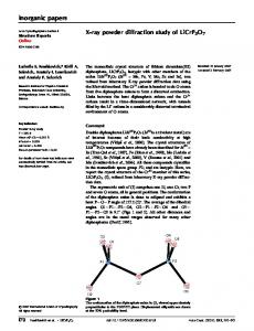
FIG. 6: Line-outs of the real part of the reconstructed complex amplitude 3D image, through the isolated single ball at the pyramid apex. Dashed lines show a simulated 3D coherent image with a cube OTF of 10 nm resolution and with a 60◦ missing sector19 . The lineout through three lines (d) demonstrates that the resolution is sufficient to clearly distinguish between different 50 nm gold spheres.
Although we cannot exactly quantify the resolution of the image, which would require knowing the object’s 3D structure, our analysis shows we can consistently retrieve phases out to the maximum spatial frequency recorded19 (further improvements in.23 A line-out through the reconstructed image can easily resolve 50 nm spheres that are touching each other (see Fig. 6). From such image line-outs, and comparisons of reconstructed X-ray images with the SEM image, we have confidence that our achieved image resolution is close to 10 nm. Further analysis of the consistency of the retrieved phases, and the
Inspired by this holographic method to help the phase retrieval step (see also23 , we developed a methodology to deposit controlled reference points near the object by metallorganic deposition using a focused ion beam. Our initial trials are illustrated in Fig. 8.
FIG. 8: SEM image of a coccolith shell deposited on a silicon nitride membrane (left). A reference point deposited with a focused ion beam produces a holographic image (right).
5 VII.
CONCLUSIONS
We have demonstrated ab-initio two dimensional images with infinite depth of focus, and three dimensional images of test objects at a resolution of 10 nm. Preliminary images of areogel foams were presented. These images of complicated and unknown objects, along with the rigorous analysis of known test objects, show the robustness of our ab initio phase retrieval technique. In the case of the aerogel particle, the reconstruction was performed “blind” without the operator (A. Barty) of the reconstruction software aware of the SEM image, or the size or shape of the object. While the recent experimental progress to date has been rapid and extremely encouraging, we are looking forward to further improvements in the technique, including faster acquisition times (with an improved beamline) that will allow us to achieve even higher image resolution. Given the scaling of required dose to the inverse fourth power of resolution2 , and estimates of coherent flux improvements achievable with an optimized beamline and undulator source, we estimate that we should be able to achieve resolutions of 2–4 nm on material science samples. Possible2 applications for the technique include characterizing the pore structure of vesicular basalt, the formation of voids in metals, and many other investiga-
∗ 1
2
3 4 5
6 7 8 9 10 11
12 13 14
Electronic address:
[email protected] J. Miao, P. Charalambous, J. Kirz, D. Sayre, Nature 400, (1999) 342. M. R. Howells, et al. J. Elect. Spect. and Rel. Phen. (2004), [arXiv:physics/0502059]. E. Lima, et al. These proceedings (2005). D. Sayre, Acta Cryst. 5, (1952) 843. D. Sayre, “Prospects for long-wavelength x-ray microscopy and diffraction”, in Imaging Processes and Coherence in Physics, Schlenker, M., M. Fink, J. P. Goedgebuer, C. Malgrange, J. C. Vi´enot, R. H. Wade, (Ed), Lecture Notes in Physics, Vol. 112, 229-235, Springer-Verlag, Berlin, 1980. J. R. Fienup, Opt. Lett. 3, (1978) 27. J. R. Fienup, Opt. Eng. 19, (1980) 297. J. R. Fienup, J. R., Appl. Opt. 21, (1982) 2758. R. P. Millane, J. Opt. Soc. Am. A 7, (1990) 394. R. H. T. Bates, Optik 61, (1982) 247. J. Miao, D. Sayre, and H. N. Chapman, J. Opt. Soc. Am A 15 (1998) 1662. T. Beetz, et al. Nucl. Instrum. Meth. A 545, (2005) 459. M. R. Howells et al, Proc. SPIE 4783, (2002) 65. I. K. Robinson, I. A. Vartanyants, G. J. Williams, M. A.
tions of the nanoworld. The techniques that we have developed will also be applied to exciting new prospects for imaging of large macromolecules and assemblies at near atomic-resolution imaging, which will be achieved using X-ray free-electron lasers24 and aligned molecule diffraction25 .
Acknowledgments
Coccolith samples were provided by J. Young from the Natural History Museum, London. This work was performed under the auspices of the U.S. Department of Energy by University of California, Lawrence Livermore National Laboratory under Contract W-7405-Eng48. This work has been supported by funding from the National Science Foundation. The Center for Biophotonics, an NSF Science and Technology Center, is managed by the University of California, Davis, under Cooperative Agreement No. PHY 0120999. The work of the Lawrence Berkeley National Laboratory participants and the operation of the ALS facility was supported by the Director, Office of Energy Research, Office of Basic Energy Sciences, Materials Sciences Division of the U. S. Department of Energy, under Contract No. DE-AC0376SF00098.
15
16 17
18
19
20
21
22 23
24 25
Pfeifer, J. A. Pitney, Phys. Rev. Lett. 87, (2001) 195505 G. J. Williams, M. A. Pfeifer, I. A. Vartanyants, I. K. Robinson, Phys. Rev. Lett. 90, (2003) 175501. J. Miao, et al. Phys. Rev. Lett., 89 (2002), 088303. J. W. Miao, K. O. Hodgson, T. Ishikawa, C. A. Larabell, M. A. LeGros, Y. Nishino, Proc. Nat. Ac. Sci. 100, (2003) 110. S. Marchesini et al. Phys. Rev. B 68, (2003) 140101(R), [arXiv:physics/0306174]. H. N. Chapman et al.: submitted (2005), [arXiv:physics/0509066]. S. Marchesini et al. Optics Express 11, (2003) 2344, [arXiv:physics/0308064]. D. R. Luke, Inverse Problems 21, (2005), 37, [arXiv:math.OC/0405208]. A. Barty, in preparation. S. Marchesini, H. N. Chapman, A. Barty, M. R. Howells, J. C. H. Spence, C. Cui, U. Weierstall, and A. M. Minor, these proceedings [arXiv:physics/0510033]. R. Neutze et al, Nature 406, (2000) 752. J. C. H. Spence, R. B. Doak, Phys. Rev. Lett. 92, (2004) 198102.