Proceeding PCIM 2000
Properties and applications of supercapacitors From the state-of-the-art to future trends Adrian Schneuwly, Roland Gallay montena components SA, 1728 Rossens, Switzerland Tel.: +41 26 411 22 ; Fax: +41 26 411 25 25 ; Email:
[email protected]
I.
Abstract
Electrochemical double-layer capacitors, also known as supercapacitors or ultracapacitors, are electrical storage devices, which have a relatively high energy storage density simultaneously with a high power density. Recent developments in basic technology, materials and manufacturability have made supercapacitors an imperative tool for shortterm energy storage in power electronics. With much higher energy density than today's capacitors and none of the problems associated with conventional battery technology, supercapacitors give an access to new power electronic and industrial storage applications. The paper presents basic supercapacitor technology, component specific properties as well as state-of-the-art product applications. The problematic nature of supercapacitor series connection for higher voltage applications is touched on. The review also deals with an energy storage system, which is based on the hybridization of rechargeable batteries and supercapacitors, with a suitable designed electronic interfacing arrangement in order to obtain a very high energy density device with a high power performance and a long lifetime. Finally, an overview over future trends regarding the supercapacitor technology as well as application scenarios, mainly in the traction domain, is given.
II.
Introduction
Supercapacitors with very high resistance. In a energy is stored Therefore such
1
are energy storage devices capacity and a low internal supercapacitor, the electrical in an electrolytic double-layer. energy storage devices are
generally called electrochemical double-layer capacitors (EDLC). Helmholtz has discovered the storage process, based on the separation of charged species in an electrolytic double layer, in 1879. ECDLs or supercapacitors (i.e. supercaps) are also known as ultracapacitors, Boostcaps , Bestcaps etc. Supercapacitors are attractive for their high energy and power densities, their long lifetime as well as their great cycle number. In addition to the high specific power the energy storage in supercapacitors is reversible in contrast to conventional batteries [1]. The electronic applications need passive components to store the electrical energy in volume and weight as small as possible. The choice of the storage device type depends in particularly on the speed of the storage process, in other words on the power required by the application. 10000 s
1000 s
100 s
10 s
1s
0.1 s
100.00
Li+ NiCd
Pb
10.00
NiMH (E'α, P'α,0 ) E'max
1.00
BOOSTCAP P'max,0
Al El Capacitors
0.10
Film-Foil-Capacitor
0.01 1
10
100
1'000
10'000
100'000
1'000'000 10'000'00 0
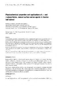
Figure 1: The Power density [W/kg] Ragone plot shows the energy density vs. the power density Actually, while the slower storage processes may be performed with batteries, the faster ones have to be done with capacitors. In general the electrical energy storage devices are of 3 types: faradaic batteries, electrostatic
Proceeding PCIM 2000
capacitors and magnetic inductors. The situation may be well summarized by the following so-called Ragone plot (Figure 1). Detailed informations on the Ragone plot are given in chapter 4.The energy density in a battery may rise to 150 Wh/kg. This is about 10 times higher than the highest expected value of a supercapacitor. The power density in a battery has difficulty to reach 200 W/kg and is therefore about 20 times smaller than the expected supercapacitor performance. The batteries suffer from several weaknesses, which exhibit a rapid decrease of their performances. The origins may be the fast charge-discharge cycles or the cold environmental temperature. The batteries have also a limited lifetime and require expensive maintenance. Through the different capacitor technology types, the EDLC presents the highest energy density. Dielectric and electrolytic capacitors, as well as ceramic capacitors show very high power densities but very low energy densities. Compared to batteries, capacitors reveal much longer lifetimes and cyclabilities. In terms of power and energy density the supercapacitor fills up the gap between the batteries and the classical capacitors, allowing new applications. The properties of the different energy storage devices are presented in Table 1. Capacitors
EDLC
Batteries
Energy density [Wh/kg]
0.1
3
100
Power density [W/kg]
107
3'000
100
Time of charge [s]
10-3-10-6
0.3-30
>1’000
Time of discharge [s]
10-3-10-6
0.3-30
1010
106
1’00010’000 1'000
Typical lifetime [years]
30
30
5
Efficiency [%]
>95
85-98
70-85
Cyclability [1]
Table 1 : Storage comparisons
component
property
part, and of an active material, which is the high surface area part. The two electrodes are separated by a membrane, the separator, which allows the mobility of the charged ions but forbids the electronic conductance. This composite is subsequently rolled or folded into a cylindrical or rectangular shape and stacked in a container. Then the system is impregnated with an electrolyte. The electrolyte may be of solid state, organic or aqueous type, depending on the application power requirement. The working voltage of supercapacitor is determined by the decomposition voltage of the electrolyte and depends mainly on the environmental temperature, the current intensity and the required lifetime. The capacitance of an EDLC can be very large, e.g. several thousands of Farads, thanks to the very small distance which separates the opposite charges at the interfaces between the electrolyte and the electrodes and thanks to the very huge surface of the electrodes.
Electrolyte
Electrodes Figure 2: Supercapacitor sketch In the following, the different materials used in supercapacitor are discussed more in detail. 3.1.1
III.
Technological aspects of supercapacitors
3.1
Cell construction
A supercapacitor cell basically consists of two electrodes, a separator, and an electrolyte (Figure 2). The electrodes are made up of a metallic collector, which is the high conducting
2
Separator
Electrode
Since the capacitance is proportional to the surface area, electrochemical inert materials with the highest specific surface area are utilized for supercapacitor electrodes in order to form a double layer with a maximum number of electrolyte ions. As high surface active materials, metal oxides, carbon and graphite are the most interesting. The main difficulties are to find cheap materials, which are
Proceeding PCIM 2000
chemically and electrically compatible with the electrolyte. Capacitors for high energy applications require electrodes made of high surface area activated carbon with appropriate surface and pore geometry. Carbonaceous materials commonly are activated carbon fibers, carbon black, active carbon, carbon fibers, carbon gel, skeleton carbon, mesocarbon as well as microbeads. The best carbon electrodes have surfaces as high as 3'000 m2 per gram of material. The electrode capacitance increases linearly with the carbon surface area and may reach a capacitance of 250 F/g. They are usually prepared from high surface area carbon powders or fibers. The powders are applied, e.g. as a paste on the metallic current collector. Such an arrangement, however, leads to a considerable contact resistance between grains and between the grains and the support. In order to overcome these problems, pressure has to be applied or the carbon powder has to be mixed with metal fibers or powders in order to increase conductivity. Recently several capacitors using high surface area electrodes composed of RuO2 based composites have been introduced [14]. Such devices have e.g. the size of a credit card and have a capacitance of 200-300 mF at 4-8 V. The RC time constant is about 5 ms. 3.1.2
Electrolyte
As mentioned above the electrolyte may be of the solid state, organic or aqueous type. Organic electrolytes are produced by dissolving quaternary salts in organic solvents. Their dissociation voltage may be greater than 2.5 V. Aqueous electrolytes are typically KOH or H2SO4, presenting a dissociation voltage of only 1.23 V. The energy density is thus about 4 times bigger for an organic electrolyte. As a consequence of the quadratic dependence of the energy density of the capacitor on the capacitor’s voltage use of an organic electrolyte would be desirable. However, if power density is important, the increase in the internal resistance (ESR) due to the lower electrolyte conductivity has to be considered as well. The electrolyte solution should therefore provide high conductivity and adequate electrochemical stability to allow the capacitor being operated at the highest possible voltages.
3
Earlier work [2] indicated TEATFB in acetonitrile as the best performing organic electrolyte system for EDLC applications. Depending on the molarity conductivities up to 60 mS/cm are possible. Covalent Associates introduced novel electrolytes known as ionic liquids. The advantage of these electrolytes are manifold, they are non-corrosive, the typical conductance is about 8 mS/cm, and the electrolytes can be used up to high temperatures of about 150 °C. Blending with acetonitrile results in a conductance of 60 mS/cm. 3.1.3
Separator
Many of the commercial available separators are designed for battery use mainly. Hence an accurate evaluation of the separator is essential to achieve the exceptional performance of EDLCs. If organic electrolytes are used, polymer (typically PP) or paper separators are applied. With aqueous electrolytes glass fiber separators as well as ceramic separators are possible. The separator allows the transfer of the charged ions but forbids the electronic contact between the electrodes. The basic principles to obtain a competitive EDLC is to collect all the following performances: high ionic electrolyte conductance, high ionic separator conductance, high electronic separator resistance, high electrode electronic conductance, large electrode surface, low separator and electrodes thickness. In Table 2 an overview over material specifications for best performance EDLCs using an organic electrolyte are given (based on model calculations). Active layer thickness Volumetric Capacitance Electrolyte Cell Voltage Current Collector Thickness Separator Porosity Separator Thickness Distributed Resistance in Pores
100 µm 100 F/cm3 0.05 S/cm, 2.5 V 25 µm 50 % 25 µm 10 x electrolyte
Table 2: EDLC best performance parameters 3.1.4 Material research Most of the recently published works [3-6] deal with developing and testing of new electrode materials on laboratory scale devices. Carbonaceous materials in their various forms
Proceeding PCIM 2000
have been studied as electrodes for the construction of EDLC energy storage devices. Activated carbon composites and fibers [7] with surfaces up to 3'000 m2/g, measured by gas adsorption, as well as carbon aerogels [8] with surface areas up to 850 m2/g have been investigated. Unfortunately a significant part of the surface area resides micropores ( 48 V will have grown to the same size and will give opportunities for the supercapacitor market. 5.1.5
GSM applications
During the short 0.5 ms pulse of 1 A, the battery voltage drops considerably. If it is below a certain limit, the phone is not longer operable. With a supercapacitor the voltage drop is reduced significantly and it takes much longer until the critical low voltage is reached during the pulse. In essence the operation time of the phone is extended. 5.1.6
Other applications
There are a variety of other very interesting applications, which also emphasizes the economically interesting aspects of the supercapacitors for high-power density applications. Additional applications may be found in:
8
SAM
Most of the applications, where supercapacitors may be involved, need an additional battery to insure a certain amount of autonomy. Thanks to the great know-how of the HTA-Lucerne in applications with supercapacitors and their integrated intelligent electronic control management systems, montena components and the HTA-Lucerne became partners in developing the already mentioned SAM (Super Accumulator Module), consisting of the hybridization of supercapacitors and batteries with an intelligent control for universal applications (Figure 9) [19]. The parallel connection of the ECDL with a battery must be done in a clever way because batteries and capacitors have a fundamental different dynamic behavior. The batteries are faradaic (redox) storage devices. During their charging or discharging the voltage remains in principle constant. The capacitors are electrostatic storage devices. The voltage changes proportionally to the charge Q. 5.3
Voltage repartition
The main difficulty with the supercapacitors is their extreme low operating voltage. In the case
Figure 9: Supercapacitor and battery in a Super Accumulator Module (SAM) [18]
of organic electrolyte for example this voltage lays between 2 and 3 Volts (with some hope to 4 Volts in future). Contrarily most powerful applications need much higher voltages up to 700 V. The main reasons of these operating
Proceeding PCIM 2000
voltages are, on one side the current reduction which requires smaller and lighter conductors, and on the other side, the voltage drop in the semiconductors which is proportionally much less important in comparison to a 2.5 V application. To reach the required application voltage the super-capacitors are connected in series to form a "system". 2 electrodynamics laws govern the voltage repartition between the single cells. In continuous operation the voltage is distributed through the cells in function of their parallel resistance. Those, which have a higher resistance, are submitted to a higher voltage. A cell with a small resistance has a behavior which looks like a short. In transient operation the voltage is distributed through the cells in function of their capacitance. Those, which have a higher capacitance, need more time to change their voltage. If all the cells had the same parallel resistance and the same capacitance, the voltage would be equal on each of them. It is actually not the case because several factors induce a scattering of the supercapacitor properties:
conducting when the voltage exceed the redact voltage. This method may be considered as a cell protection. When the system is working at voltage lower then the nominal one, the cell voltage distribution is not corrected. The aging will be different from one cell to the other. The efficiency is improved to 90%. With the active electronic (Figure 10), the system efficiency may rise to 97%. The losses are due to the transistor resistance.
Figure 10 : Electronic schema and setup of the active voltage sharing with Boostcaps [21]
ú the manufacturing process (5-10%) ú the temperature gradient in the system ú the cell aging To prevent the decompostion of the electrolyte, which causes a supercapacitor failure, the voltage between the electrodes must be maintained under the electrolyte decomposition potential. This later depends on the electrolyte type, but also on the materials which are used for the electrodes, the conductors and the can. The voltage repartition is not only important for security reason but also to assure an equal aging of the cells. The problem is well known for electrolytic capacitor where the voltage repartition is generally controlled with resistors. It does mean finally that each supercapacitor cell must be controlled or protected. The different methods, which are used to equilibrate the voltage through the cells, are either based on external parallel resistances, on Zener diodes or on an active power electronic [21]. In the case of the external resistance, they have to be about typically 10 time less resistive then the internal parallel resistances in order to dominate them. The losses are therefore much more important. The typical system efficiency may be estimated to 16%. In the case of Zener diodes, the principle is that the diode start to be
9
The costs of the system are strongly related to the electronic components choice, especially to the current they have to manage. This later depends on the level of the cell properties unbalancing. Performant manufacturing processes and a good temperature repartition in the system is very important to reduce costs. To determine the electronic components size it is necessary to analyze the type of voltage stresses in the application. Generally steady state and transient stresses are superposed. The parallel resistance distribution is important for capacitors, which are permanently charged. The time constant to reach a steady state behavior is given by T = Rp C which is typically equal to about 500 hours.
VI.
Conclusions
Proceeding PCIM 2000
Supercapacitors may be used wherever high power delivery or electrical energy storage is required. Therefore numerous applications are possible. The use of supercapacitors allows a complementation of normal batteries. In combination with batteries the supercapacitors improve the maximum instantaneous output power as well as the battery lifetime. In order to increase the voltage across a supercapacitor device, a series connection is needed. An active voltage repartition device has been defined which ensures no over-voltage over any supercapacitor and an optimal efficiency.
VII.
Acknowledgements
The authors gratefully acknowledge collaborations with A. Züttel, Ch. Emmenegger and L. Schlapbach of the University of Fribourg, L. Diederich and P. Milani from the University of Milano, R. Kötz, S. Müller and M. Bärtschi from the PSI in Villigen, V. Härri, P. Erni and S. Egger from the HTA in Lucerne and A. Rufer from the LEI EPF in Lausanne. The authors are very much indebted to the CREE-RDP, PSEL, BFE and CTI, which are supporting the EDLC research.
VIII. References [1] A. Schneuwly, R. Gallay, Proc. Power Conversion PCIM 1999 [2] D. Ue, K. Ida, S. Mori, J. Electrochem. Soc. 141, 1994, 2989 [3] A. Yoshida, S. Nonaka, I. Aoki, A. Nishino, J. Power Sources 60, 1996, 213 [4] Y. Kibi, T. Saito, M. Kurata, J. Tabuchi, A. Ochi, J. Power Sources, 60, 1996, 219 [5] H. Shi, Electroch. Acta, 41, 1996, 1633 [6] L. Diederich, P. Milani, A. Schneuwly, R. Gallay, Applied Physics Letters 75, Nr 17, 1999, 2662 [7] I. Tanahashi, A. Yoshida, A. Nishino, J. Electrochem. Soc. 137, 1990, 3052 [8] S.T. Mayer, R.W. Pekala, J.L. Kaschmitter, J. Electrochem. Soc. 140, 1993, 446 [9] S. Iijima, Nature 354, 1991, 56 [10] T.W. Ebbesen, Nature 358, 1992, 220
10
[11] C. Emmenegger, A. Züttel, L. Schlapbach, A. Schneuwly, R. Gallay, Applied Surface Science, to be printed [12] M.Endo, K. Takeuchi, S. Igarashi, K. Kobori, M. Shiraishi, H.W. Kroto, J. Phys. Chem. Solids 54, 1993, 1841 [13] P.L. McEwen, Nature 393, 1998, 16 [14] A. Beliakov, ELIT company, 9th Seminar ECDL Deerfield Beach FL, 1999 [15] D. Evans, 9th Seminar ECDL Deerfield Beach FL, 1999 [16] R. Kötz, Proc. 7th Seminar ECDL Deerfield Beach FL, 1994 [17] Proc. 7th - 9th Seminar ECDL Deerfield Beach FL, 1997-1999 [18] O. Haas and E.J. Cairns, Annu. Rep. Prog. Chem., Sect. C, 95, 1999, 163 [19] V. Härri, SEV/VSE 1, 1999, 25 [20] J. Nickerson, Fullpower Technologies, 9th Seminar ECDL Deerfield Beach FL, 1999 [21] P. Barrade, S. Pittet, A. Rufer, Proc. Power Conversion PCIM 1999