This is to certify that the dissertation titled “Protocols For Wireless ATM Networks ... access contention, scheduling, and provisioning QoS to various traffic classes ...
PROTOCOLS FOR WIRELESS ATM NETWORKS
B.TECH PROJECT REPORT
submitted by
JATINDER PAL SINGH (96195) SACHIN ADLAKHA (96229)
under the guidance of
PROF. SURENDRA PRASAD DR. SUBRAT KAR
DEPARTMENT OF ELECTRICAL ENGINEERING INDIAN INSTITUTE OF TECHNOLOGY, DELHI MAY 2000
CERTIFICATE This is to certify that the dissertation titled “Protocols For Wireless ATM Networks” which is being submitted by Jatinder Pal Singh (96195) and Sachin Adlakha (96229) to the Department of Electrical Engineering, Indian Institute of Technology Delhi, is a record of bonafide work carried out under my (joint) guidance and supervision.
______________________________ Prof. Surendra Prasad
This is to certify that the dissertation titled “Protocols For Wireless ATM Networks” which is being submitted by Jatinder Pal Singh (96195) and Sachin Adlakha (96229) to the Department of Electrical Engineering, Indian Institute of Technology Delhi, is a record of bonafide work carried out under my (joint) guidance and supervision.
______________________________ Dr. Subrat Kar
i
Acknowledgements We would like to express our deepest gratitude towards our guides Professor Surendra Prasad and Dr. Subrat Kar of the Department of Electrical Engineering, Indian Institute of Technology Delhi for their immense encouragement, guidance and support throughout the course of the project. We are also grateful to Miss Anubala and Mr. Deepak Mittal for proving us with a cordial environment in the laboratory. Finally we are grateful to our colleagues at the department of Electrical Engineering for their help, useful suggestions and for their delightful company.
Jatinder Pal Singh
Sachin Adlakha
96195
96229
ii
Abstract With the ever increasing demand for easy portability and maneuverability of devices supporting advanced mobile multimedia applications, the need for the adaptation of broadband infrastructure to wireless scenario has arisen. Provisioning ATM over wireless medium is fraught with challenges relating to user mobility management and channel access. In this dissertation we address the issues of handover and the adaptation of medium access policies of various traffic classes with different Quality of Service in wireless scenario. Mobility management is an important consideration in provisioning multimedia applications over wireless channel. Inter-cell handovers should be seamless vis-a-vis resource availability to the mobile hosts. This is crucial as the mobile hosts may support ATM traffic with stringent QoS requirements. We propose the Dynamic Resource Allocation with network initiated Bandwidth Renegotiation (DRABR) strategy, which enhance call admission efficaciousness by introducing bandwidth renegotiation vis-a-vis the already existing connections. We compare the performance of this proposed protocol with already existing mechanisms for bandwidth allocation with regard to their effectiveness to admit new calls and also the probability of blocking a handover call. We also address the adaptation of medium access policies of various traffic classes with different Quality of Service requirements, to the wireless scenario. Via simulations, we do the performance appraisal of a medium access protocol which is optimal in channel access contention, scheduling, and provisioning QoS to various traffic classes. We also describe how ATM QoS requirements can be mapped to different weights pertinent to scheduling. We analytically derive bound on the buffer requirements of various classes and also on the delays suffered by head of line packet in each class. A generic MAC simulator is also developed which can be used to study the effect of various individual features on the overall performance of the network.
iii
Table of Contents 1.
2
Introduction
1
1.1
Need For Wireless ATM
2
1.2
Organization of the Report
4
Wireless ATM: Concepts & Issues
6
2.1
6
Wireless Technologies
2.2 ATM: A Brief Overview
7
2.2.1
Traffic Classes
9
2.2.2
Quality of Service Parameters
10
2.2.3
The Protocol Reference model
12
2.3
Wireless ATM Architecture
14
2.4
Issues and Challenges in Wireless ATM
15
2.4.1
Challenges Related to the Mobility of Wireless Users
16
2.4.2
Challenges Related to providing Access
17
3
Handover Strategies in Wireless ATM
18
4
Medium Access in Wireless ATM
21
4.1
Performance Metrics
22
4.2
Attributes
23
4.3 Some MAC Protocols
26
4.3.1
Slotted Aloha
26
4.3.2
Polling Apostolas
26
4.3.3 DQ-RUMA
26
4.3.4 DSA++
27 iv
4.3.5 MASCARA
5
27
Scheduling Disciplines in Wireless ATM Networks
30
5.1
31
Scheduling Requirements
5.2 Scheduling Policies
6
32
5.2.1
Generalized Processor Sharing
33
5.2.2
Weighted Fair Queuing (WFQ)
33
5.2.3
Start Time Fair Queuing
34
A Novel Strategy for Handovers in Wireless ATM Networks
35
6.1
Protocol Implementation and Simulation
39
7
Scheduling Proposals for Wireless ATM
52
8
Medium Access in Wireless ATM: Models and
9
Proposals
57
8.1
Frame Structure
57
8.2
Mapping ATM QoS Parameters
58
8.3
Buffer Calculations and Delay Bounds for Various Classes
59
8.4
Traffic Modeling
61
8.5
Channel Modeling
64
8.6
Channel Access
65
Performance Appraisal and Analysis of MAC Protocol 66 v
9.1
Development of WATM Simulator
66
9.2
Simulation Results
67
9.2.1
Network Throughput in Various Traffic Intensity Scenarios
9.2.2
67
Average Delays in Varying Traffic Intensity
71
Scenarios
9.2.3 Delay Jitter in Varying Traffic Intensity Scenarios 9.2.4
Buffer Requirements for Various Traffic Intensity Scenarios
10
11
74 77
Conclusions
80
10.1 Summary of Results and Contributions
80
10.2 Topics for future Research
81
References
82
vi
List of Tables 2.1
QoS Parameters Defined for Various Classes
11
4.1
Summary of Attributes for Various MAC Protocols
29
List of Figures 2.1
The Protocol Reference Model
13
2.2
WATM Architecture
15
6.1
Probability of New Connections Drops vs. Class Type
41
6.2
Probability of Handoff Connections Drops vs. Class Type42
6.3
Blocking Probability of Handoff Connections vs. Connection Arrival Rate for Class I
6.4
Blocking Probability of Handoff Connections vs. Connection Arrival Rate for Class II
6.5
47
Blocking Probability of New Connections vs. Connection Arrival Rate for Class II
6.9
46
Blocking Probability of Handoff Connections vs. Connection Arrival Rate for Class V
6.8
45
Blocking Probability of Handoff Connections vs. Connection Arrival Rate for Class IV
6.7
44
Blocking Probability of Handoff Connections vs. Connection Arrival Rate for Class III
6.6
43
48
Blocking Probability of New Connections vs. Connection Arrival Rate for Class III vii
49
6.10 Blocking Probability of New Connections vs. Connection Arrival Rate for Class IV
50
6.11 Blocking Probability of New Connections vs. Connection Arrival Rate for Class V
51
8.1
Frame Structure
57
8.2
Two State Model for VBR Traffic Modeling
54
9.1
Throughput vs. CBR Traffic Intensity
68
9.2
Throughput vs. VBR Traffic Intensity
69
9.3
Throughput vs. ABR Traffic Intensity
70
9.4
Average CBR Delay vs. Traffic Intensity
71
9.5
Average VBR Delay vs. Traffic Intensity
72
9.6
Average ABR Delay vs. Traffic Intensity
73
9.7
CBR Delay Jitter vs. Traffic Intensity
74
9.8
VBR Delay Jitter vs. Traffic Intensity
75
9.9
ABR Delay Jitter vs. Traffic Intensity
76
9.10 CBR Buffer Requirements vs. Varying Traffic Intensity 77 9.11 VBR Buffer Requirements vs. Varying Traffic Intensity 78 9.12 CBR Buffer Requirements vs. Varying Traffic Intensity 79
viii
Chapter 1 Introduction Man’s desire to communicate has manifested in great developments in the field of telecommunications. The development of Telephone in 1875-1876 was the first step in realizing this desire. From then there has been no looking back. The development of Internet provided the means to communicate voice, data and other forms of information. The next step was to extend this in wireless domain leading to seamless connectivity. The emergence of cellular networks supported pedestrians and vehicular voice and data services. Two emerging concepts that are changing the field of telecommunications are broadband networks and wireless communications. Currently, the two communications entities are ‘disjoint’. Broadband networks are characterized by packet-based transport, bandwidth-on demand, and multimedia traffic integration. Network resources are statistically shared, resulting in a flexible and efficient transport mechanism. Early deployment of wireless networks were based on narrowband networks and were characterized by fixed bandwidth requiring transmission of digital voice signal over a hostile physical channel. As demand for broadband services is fueled by the increased usage of on-line services, Internet access, video-on-demand, and multimedia archiving, researchers and service providers are trying to explore mechanisms that would extend this form of broadband connectivity from wired domain to wireless domain. The integration of the two, wireless ATM, could provide nomadic access to broadband networks and the infrastructure to support extended wireless services. Because of the wide range of services supported by ATM networks, ATM technology is expected to become the dominant networking technology for both public infrastructure networks and LANs. ATM infrastructure can support all types of services, from timesensitive voice communications and multimedia conferencing to bursty transaction processing and LAN traffic. Extending the ATM infrastructure with wireless access meets the needs of users and customers who want a unified end-to-end networking infrastructure 1
with high performance and consistent service. Wireless ATM adds the advantages of mobility to the already great service advantages of ATM networks.
1.1 Need for Wireless ATM The growth of wireless communications paired with the rapid developments in asynchronous transfer mode (ATM) networking technology signals the start of a new era in telecommunications. The growth of cellular radio communications in the past decade has been remarkable. The number of cellular users has exceeded all predictions on cellular’s use. Demand for cellular communications has placed a heavy demand on the capacity of wireless/air interfaces and the network resources available. The success of cellular mobile communications has spurned the telecommunications industry to push the implementation Personal Communications Services (PCS). PCS will provide voice, text, video and data. As a result, the demand for higher transmission speed and mobility is even greater. Since the beginning the concept of ATM is for end-to-end communications (i.e. in a WAN environment). The communication protocol will be the same (i.e. ATM), and companies will no longer have to buy extra equipment (like routers or gateways) to interconnect their networks. Also, ATM is considered to reduce the complexity of the network and improve the flexibility while providing end-to-end consideration of traffic performance. That is why researchers have been pushing for an ATM cell-relay paradigm to be adopted as the basis for next generation wireless transport architectures. There are several factors that tend to favor the use of ATM cell transport for a personal communication network. These are: •
Flexible bandwidth allocation and service type selection for a range of applications
•
Efficient multiplexing of traffic from bursty data/multimedia sources
•
End-to-end provisioning of broadband services over wireless and wired networks 2
•
Suitability of available ATM switching equipment for inter-cell switching
•
Improved service reliability with packet switching techniques
•
Ease of interfacing with wired B-ISDN systems that will form the telecommunications backbone
In general, interworking may always be seen as a solution to achieve wireless access to any popular backbone network but the consequence, in this case, is a loss of the ATM quality of service characteristics and original bearer connections. The more interworking there is in a network, the less harmonized the services provided will be. Therefore, it is important to be able to offer appropriate wireless extension to the ATM network infrastructure. One of the fundamental ideas of ATM is to provide bandwidth on demand. Bandwidth has traditionally been an expensive and scarce resource. This has affected the application development and even the user expectations. So far, application development has been constrained because data transmission pipes cannot support various quality of service parameters, and the maximum data transmission bandwidth that the applications have to interface with is relatively small. Finally, ATM has removed these constraints. Bandwidth has become truly cheap and there is good support for various traffic classes. A new way of thinking may evolve in application development. The progress towards ATM transport in fixed networks has already started and the market push is strong. It can be expected that new applications will evolve that fully exploit all the capabilities of the ATM transport technology. The users will get used to this new service level and require that the same applications be able to run over wireless links. To make this possible the wireless access interface has to be developed to support ATM quality of service parameters. The benefits of a wireless ATM access technology should be observed by a user as improved service and improved accessibility. By preserving the essential characteristics of ATM transmission, wireless ATM offers the promise of improved performance and quality of service, not attainable by other wireless communications systems like cellular systems,
3
cordless networks or wireless LANs. In addition, wireless ATM access provides location independence that removes a major limiting factor in the use of computers and powerful telecom equipment over wired networks.
1.2 Organization of the Report In this dissertation we propose and simulate a Medium Access Protocol for a Wireless ATM Scenario. Having focused on the issues of Mobility Management in the Wireless ATM networks in the first part of our work, we here focus on another important issue of providing channel access. We describe the current wireless technologies that are of importance in context of WATM in the beginning of the next chapter. We also discuss the ATM fundamentals, describing about the traffic classes proposed, their associated QoS requirements, and the protocol reference model. In the third section of the chapter we explain how ATM would be coupled with wireless medium and describe the WATM architecture .The challenges that need to be overcome before Wireless ATM is deployed are detailed in the following section. In Chapter three and six we discuss the handover strategies in Wireless ATM scenario, their discussions and implementation. This work was accomplished during the first half of the project. Chapter four describes various issues pertinent to Medium Access in Wireless ATM Networks. It identifies various performance metrics that are used to compare several MAC protocols and various attribute that a MAC protocol should possess. We also discuss in brief various MAC protocols that have been proposed and compare them with respect to the attribute described previously. The fifth chapter takes up the issue of scheduling, describing the requirements that a scheduling discipline must satisfy and also discusses various scheduling disciplines described in literature. 4
Chapter seven describes a scheduling algorithm which has been modified to take into account the wireless channel error and also describes how such a policy can be adapted to suit various QoS requirements desired by various traffic classes. In chapter eight, we discuss various implementation issues like the translation of ATM QoS parameters to weights useful for scheduling and the frame structure used in the simulations for Medium Access. We also analytically derive the buffer lengths required and the delay bound that are achieved for various classes. We then describe the channel and the traffic models used in the simulations and also discuss the channel access policies employed in our simulator. Chapter nine deals with the performance appraisal of the proposed MAC protocol. Various pertinent results pertaining to the throughput, average delay, delay jitter and buffer requirements have been plotted and analyzed. Chapter ten gives overview of the contributions and the achievements and also lists some of the important topics which require further thought, while chapter eleven lists important references used and cited in the body of the report.
5
Chapter 2 Wireless ATM: Concepts & Issues 2.1 Wireless Technologies Wireless technologies and systems are fairly new to telecommunications and are still emerging on the scene. Currently, wireless LAN technologies are comprised of infrared, UHF radio, spread spectrum, and microwave radio. These technologies can range from frequencies in the MHz (US), GHz (Europe), to infrared frequencies. The personal communications network (PCN) can either use code-division multiple access (CDMA), or time-division multiple access (TDMA). There is a considerable controversy among experts in the field regarding the relative merits of spread spectrum (CDMA) and narrow-band (TDMA) for private communication network (PCN). The preferred technique may actually vary with the specific PCN application scenario to be addressed. Below is a brief description of CDMA and TDMA. •
Spread Spectrum (CDMA): The term spread spectrum defines a class of digital radio systems in which the occupied bandwidth is considerably greater than the information rate. The term code-division multiple access (CDMA) is often used in reference to spread spectrum systems and refers to the possibility of transmitting several such signals in the same portion of spectrum by using pseudo random codes for each one. This can be achieved by either frequency hopping (A series of pulses of carrier at different frequencies, in a predetermined pattern), or direct sequence (A pseudo random modulating binary waveform whose symbol rate is a large multiple of the bit rate of the original bit stream) spread spectrum.
•
Time Division Multiple Access (TDMA): TDMA divides the radio carriers into an endlessly repeated sequence of small time slots (channels). Each conversation occupies just one of these time slots. So instead of just one conversation, each radio carrier carry’s
6
a number of conversations at once. With the development of digital systems TDMA is being more widely used.
2.2 ATM: A Brief Overview Asynchronous Transfer Mode (ATM) networks aim to combine the flexibility of the Internet with the per-user quality of service guarantees of the telephone network. They are designed for the high bandwidth, scalability and manageability. ATM Networks are based on some important concepts: 1.
Virtual circuits
2.
Fixed-size packets or cell
3.
Small packet size
4.
Statistical multiplexing
5.
Integrated services
Together, these ideas allow us to build networks that can carry multiple classes of traffic (unlike the telephone network) with quality of service guarantees provided to individual streams (unlike the Internet). They also enable large, parallel switches and provide a uniform framework for network management. In ATM networks, the data is divided into small, fixed length units called cells. The cell is 53 bytes. Each cell contains a 5-byte header; this header contains the identification, control priority, and routing information. The other 48 bytes are the actual data. ATM does not provide any error detection operations on the user payload, inside the cell, and also offers no retransmission services. ATM switches support two kinds of interfaces: UNI (User Network Interface) and NNI (Network Node Interface). UNI connects ATM end systems (hosts, routers, etc.) to an ATM switch, while a NNI may be imprecisely defined as an interface connection between two ATM switches. The ITU-T Recommendation requires that an ATM connection be identified with connection identifiers that are assigned for each user connection in the ATM network.
7
At the UNI, the connection is identified by two values in the cell header: VPI (Virtual Path Identifier) and the VCI (Virtual Channel Identifier). Both VPI and VCI can combine together to form a virtual circuit identifier. There are two fundamental types of ATM connections: 1. PVC (Permanent Virtual Connections): •
A PVC is a connection set up by some external mechanism, typically network management
•
In this setup switches between a source and destination ATM, are programmed with the appropriate VPI/VCI values
•
PVCs always require some manual configuration.
2. SVC (Switched Virtual Connections): •
A SVC is a connection that is set up automatically through a signaling protocol
•
SVCs do not require the manual interaction needed to set up PVC’s and, as such, are likely to be much more widely used
•
All higher layer protocols operating over ATM primarily use SVCs
A unique distinguishing feature of ATM networks is that they categorize traffic with different characteristics and requirements into traffic classes, provisioning QoS guarantees for various service categories on a per-class basis. For ATM, Quality of Service (QoS) parameters are used to specify traffic requirements for individual streams of traffic such as audio data or compressed video that are switched across the network. To guarantee QoS, an ATM switch must maintain pre-established levels of bandwidth, delay and jitter for individual virtual circuit. The ATM forum has specified several Quality of Service (QoS) categories:
8
1. CBR : Constant Bit Rate 2. rt-VBR : Real time Variable Bit Rate 3. nrt-VBR: Non-Real Time Variable Bit Rate 4. ABR: Available Bit Rate 5. UBR: Unspecified Bit Rate
2.2.1 Traffic Classes According to ATM forum, five categories of classes have been identified for the ATM layer service architecture. These classes are described below and their properties summarized. 1. Constant Bit Rate (CBR): This class is used for emulating circuit switching. The cell rate is constant. Cell loss ratio is specified Cell Loss Priority CLP=0 cells and may or may not be specified for CLP=1 cells. Examples of application that can use CBR include Interactive Audio e.g. Telephone Audio Distribution e.g. Radio Interactive Video e.g. Videoconference 2. Unspecified Bit Rate (UBR): This class is designed for those data applications that want to use any leftover capacity and are not sensitive to cell loss or delay. Such connections are not rejected on the basis of bandwidth shortage (no connection admission control) and not policed for their usage behavior. During congestion, the cells are lost but the sources are not expected to reduce their cell rate. Instead, these applications have their own higher-level cell loss recovery and retransmission mechanisms. Examples of applications that can use this service include: •
Interactive Text,
•
Data and image transfer
•
Text, data and image messaging
•
Remote terminal
9
3. Available Bit Rate (ABR): This class is designed for normal data traffic such as file transfer and email. Although the standard does not require the cell transfer delay and cell loss ratio to be guaranteed or minimized, it is desirable for switches to minimize the delay and loss as much as possible. Depending upon the Congestion State of the network, the source is required to control its rate. The users are allowed to declare a minimum cell rate, which is guaranteed to the connection by the network. Most connections will ask for minimum cell rate of zero. Those with higher minimum cell rate may be denied admission if sufficient bandwidth is not available. 4. Variable Bit Rate (VBR) Real time and Non Real Time: This class allows users to send at a variable rate. Statistical Multiplexing is used and so there may be small random loss. Depending upon whether the application is sensitive to delay or not this class is further divided into two categories: Real Time and Non Real Time VBR. While cell transfer delay is specified for both categories, Cell Delay Variation is specified only for real-time VBR.
2.2.2 Quality of Service Parameters: While setting up a connection on ATM networks, users can specify the following parameters related to the desired quality of service: 1. Peak Cell Rate (PCR): The maximum instantaneous cell rate at which the user will transmit. For Bursty traffic, the intercell interval and cell rate varies considerably 2. Sustained Cell Rate (SCR): This is the average cell rate as measured over a long interval of time. 3. Cell Loss Ratio (CLR): The percentage of cells that are lost in the network due to error and congestion and are not delivered to the destination Cell Loss Ratio = Lost Cells / Transmitted Cells
10
Each ATM cell has Cell Loss Priority (CLP) bit in the header. During congestion, the network first drops cell that have CLP bit set. Since the loss of CLP =0 cell is more harmful to the operation of the application, CLR can be specified separately for cell with CLP=1 and those with CLP=0. 4. Cell Transfer Delay (CTD): The delay experienced by a cell between network entry and exit points is called the cell transfer delay. It includes propagation delays, queuing delays at various intermediates switches, and service times at queuing points. 5. Cell Delay Variation (CDV): This is the measure of variance of CTD. High variation implies larger buffering for delay sensitive traffic such as voice and video. 6. Minimum Cell Rate (MCR): The minimum rate desired by the user. 7. Burst Tolerance (BT): This determines the maximum burst size that can be sent at the peak rate. This bucket size parameter for the leaky bucket algorithm that is used to control the traffic entering the network. The algorithm consists of putting all arriving cells in a buffer (bucket) which is drained at the sustained cell rate (SCR). The maximum number of back to back that can be sent at the peak cell rate is called maximum burst size (MBS). BT and MBS are related as follows: BT = ( MBS-1)[ (1/ SCR) - (1/PCR)]
The QoS parameters specified for each class are shown in table below:
Table 2.1: QoS Parameters Defined for Various Classes Notation
CBR
rt-VBR
nrt-VBR
ABR
UBR
PCR
√
√
√
√
√
√
√
SCR
11
CLR
√
√
CTD
√
√
CDV
√
√
√
√
MCR MBS
√
√
√
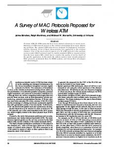
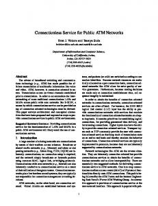
2.2.3 The Protocol Reference Model The protocol reference model illustrating how the wireless network can be integrated with the fixed ATM network is shown in Fig 2.1. It is composed of the user plane, which is responsible for the user information transfer and the control plane, which is responsible for setting up and releasing connection. The user plane does not involve any ATM adaptation layer at the base station (B.S); therefore ATM cells are transported between ATM nodes and mobile terminals (MT) as transparently as possible. In other words, this kind of native approach treats the ATM cell as the payload data field for the DLC layer. The AAL, which is found in the protocol stack of the MT, is designed to act as the interface between user applications and the ATM layer. As such, it is expected to enhance the service provided by the ATM layer, based on the specific requirements of various applications such as voice, video and data. The ATM layer consists of Virtual Channel (VC) and Virtual Paths (VP) levels, and is responsible for the routing of the cells using identification fields in the cell header. Among the other tasks, the transmitting ATM layer adds the 5 byte header on the ATM cell; the receiving ATM layer processes this header, then strips it away before passing the rest of the cell to the AAL. Below the ATM layer the DLC and MAC layers are allocated. These two layers are used to enhance the physical layer transport capability. In particular, the DLC layer is introduced to improve the performance degradation due to the high bit error in the wireless link, while the MAC layer is responsible for sharing the capacity of the wireless channel according to the bandwidth explicitly required by each VC. Connections, or VCs, between MTs and the rest
12
of the network are established and released with signal procedures in the SIG layer of the control plane.
SIG
INTERNETWORKING
SIG
SAAL
SAAL
SAAL
SAAL
ATM
ATM
ATM
ATM
DLC
DLC
MAC
MAC
PHY
PHY
W/L
W/L
MT
BASE STATION
ATM NODE
CONTROL PLANE APP. LAYER
AAL ATM DLC MAC W/L
ATM
ATM
DLC MAC
PHY
ATM PHY
W/L
USER PLANE
Figure 2.1 The Protocol Reference Model The BS terminates control signaling to/from MTs and carries out call admission control (CAC), then sends the SETUP message to the ATM node after inter-networking at the BS. A
13
connection is granted when the traffic contract (contains information such as peak cell rate, maximum cell delay, sustainable cell rate, burst tolerance, etc.) of an MT is examined, revealing that the connection can be supported through both networks (wired/wireless) at its required QoS level. The BS based on the information of the traffic contract carries out wireless channel control for the MT. the layer below the SIG is the signaling ATM adaptation layer (SAAL) and supports the transport of the signaling protocol and mobility function protocol. The structure of the overall protocol does not call for the ATM node to carry any function related to the wireless channel control. However the BS gets more complex because it needs to terminate the SAAL and to carry out the CAC channel control and mobility management. Thus the BS are equivalent to a small ATM switch which facilitates adding the proposed system to existing ATM networks.
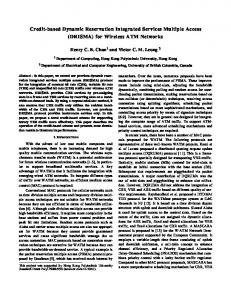
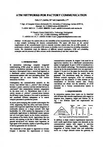
2.3 Wireless ATM Architecture The architecture proposed for wireless ATM is composed of a large number of small transmission cells called Pico cells. Each Pico cell is served by a base station. All the base stations in the network are connected via the wired ATM network. The use of ATM switching for intercell traffic also avoids the crucial problem of developing a new backbone network with sufficient throughput to support intercommunication among large number of small cells. To avoid hard boundaries between Pico cells, the base stations can operate on the same frequency. Reducing the size of the Pico-cells has major advantages in mitigating some of the major problems associated with in-building wireless LANs. The main difficulties encountered are the delay due to multi-path effects and the lack of a line-of-sight path resulting in high attenuation. Pico-cells can also have some drawbacks as compared to larger cells. There are a small number of mobiles, on average, within range of any base-station, so base-station cost and connectivity is critical. As cell size is reduced, hand-over rate also increases. By using the same frequency, no hand-over will be required at the physical layer. The small cell size 14
also gives us the flexibility of reusing the same frequency, thus avoiding the problem of running out of bandwidth. The mobile units in the cell communicate with only the base-station serving that particular cell, and not with other mobile units. The basic role of the base station is interconnection between the LAN or WAN and the wireless subnets, and also to transfer packets and converting them to the wired ATM network from the mobile units. In traditional mobile networks, transmission-cells are “colored” using frequency division multiplexing or code division multiplexing to prevent interference between cells. Coloring is a wasteful of bandwidth because in order for it to be successful there must be areas between re-use which are idle. These inactive areas could potentially be used for transmission. An illustration of wireless base station connected to an ATM switch is shown in figure 2.2.
MT BS 1
MT BS 2
BS 3
ATM SWITCHING STATION Figure 2.2 WATM Architecture
2.4 Issues and Challenges in Wireless ATM A typical reaction to the concept of wireless ATM is to question the compatibility of several aspects of the ATM protocol and the wireless channel. First, considering the fact that ATM was designed for the media whose bit error rates are very low (about 1010), it is questioned
15
whether ATM will work at all in the highly noisy wireless environment. The environment in question is a multi-access channel that may also be time varying. Second, the wireless channel is an expensive resource in terms of bandwidth, whereas ATM was designed for bandwidth-rich environments. Every ATM cell carries an overhead of about 10%. This is considered too high in a wireless environment where bandwidth is precious. In addition, the potential need to transmit single ATM cell means the system should be capable of transmitting individual cells. However, the physical layer overhead associated with the transmission of individual cells, due to channel equalization and timing can exceed leading to inefficiency which may outweigh the advantages of the wireless access. Supporting wireless users in an ATM network presents two sets of challenges to the existing ATM protocols. The First set includes problems that arise due to the mobility of the wireless of the users. The second set is related to providing access to the wireless ATM network.
2.4.1 Challenges Related to the Mobility of Wireless Users The ATM standards proposed by the International Telecommunication Union (ITU) are designed to support the wireline users at fixed locations; on the other hand, wireless users are mobile. Current ATM standards do not provide for any provisions of support of location lookup and registration transactions that are required by the mobile users. They do not support hand-offs and rerouting functions that are required to maintain connectivity to the backbone ATM network during a move. If a wireless user moves while he is communicating with another user or a server in a network, the network may need to transfer the radio link of the user between radio access points in order to provide seamless connectivity to the user. The transfer of a user’s radio link is referred to as hand-off. During a hand-off event, the user’s existing connection may need to be rerouted in order to meet delay, quality of service or cost criteria or simply to maintain the connectivity between two users or between a server and a user. Since the existing ATM protocols are designed for wireline networks with fixed users, support for rerouting of existing user is not included in ATM standards. Rerouting is critical to wireless networks which need to maintain connectivity to a wireless user through multiple, geographically dispersed radio access points. In mobile networks, as end points move, segments of connections have to be torndown and re-establishes. Maintaining cell
16
sequence and connection QoS while performing hand-offs are important requirements in wireless ATM networks.
2.4.2 Challenges Related to Providing Access ATM key benefit of a wireless network is providing tetherless access to the subscribers. The most common method for providing tetherless access to a network is through the use of radio frequencies. There are two problems that need to be addressed while providing access to an ATM network by means of radio frequencies: •
Error Performance of the Radio Link: ATM networks are designed to utilize highly reliable fiber optical or very reliable copper based physical media. These physical media have very low probability of bit error and hence ATM does not include error-correcting mechanism. In order to support ATM traffic in a wireless ATM network, the quality of radio links needs to be improved by error correction and detection.
•
Multiple Access for Wireless ATM Networks: A wireless ATM network needs to support multiple traffic types with different priorities and quality of service guarantees. A Medium Access control protocol that support multiple users, multiple connections per user and service priorities with quality of service requirements must be developed in order to maintain full compatibility with existing ATM protocols. This medium access protocol needs to make the maximum use of shared radio resource and needs to achieve full utilization of radio frequencies in a variety of environments.
17
Chapter 3 Handover Strategies in Wireless ATM A Wireless ATM Network is typically organized into geographical regions called cells. The mobile users in a cell are served by a base station. Before a mobile user can communicate with other users in the network, connection must be established between the users. The establishment and maintenance of a connection in a wireless network is the responsibility of the base station. To establish a connection, a mobile user must specify its traffic characteristics and quality of service (QoS) needs. This specification may either implicit or explicit depending on the type of services provided by the network. Future Wireless networks such as based on ATM will have to provide support for multimedia services where traffic characteristics and QoS needs of a connection may not be known a priori to the base station. In this case, the mobile user must explicitly specify the traffic characteristics and the QoS needs as part of the connection request. When a user moves from one cell to another, the base station in the new cell must take the responsibility for all the previously established connections. ATM significant part of this responsibility involves allocating sufficient resources in the cell to maintain the QoS needs of the established connection(s). If sufficient resources are not allocated, the QoS needs may not be met, which in turn may result in premature termination of the connection. Since premature termination of established connection is usually more objectionable than rejection of a new connection request, it is beneficial that the network gives higher priority to the hand-off connection requests. Many different strategies have been proposed to provide priorities to handoff requests. The basic idea of these admission control strategies is to a priori reserve resources in each cell to deal with handoff requests. The reservation typically occurs in form of “guard channels” where a new connection request is established if and only if the total available channels or capacity is greater than a predetermined threshold. The strategies proposed differ in how the number of guard channels is chosen by the base station. Based on these following strategies have been proposed in literature.
18
A. Fixed (f) Strategy: In this strategy, each base station sets aside f% of its capacity for dealing with hand-offs requests. This is achieved by choosing the guard threshold values to be f% of the cell's capacity. B. Static (k) Strategy: The key limitation of the fixed (f) strategy is that the threshold values are not directly based on the effective bandwidths of the connection requests. The static (k) strategy on the other hand is cognizant of the effective bandwidths of the hand-off requests. In this strategy, the base station is assumed to be aware of the steady fraction of the connection requests for each class τ . This fraction may be determined from historic traffic information available to the base station. Let pτ denote the fraction of connection requests for class τ. Then the expected effective bandwidth for each hand-off request is given by: ∑i = 1M piφi
where φ represents the bandwidth for each class.
If all connection requests are identical, then this strategy is equivalent to selecting k guard channels. C. Adaptive Resource Allocation /EXPECTEDMAX strategy: In this strategy, each base station dynamically adapts the guard threshold values based on current estimates of the rate at which mobiles in the neighboring cells are likely to incur hand-offs into this cell. This algorithm maintains a target probability for hand-offs request, despite fluctuations in the connection request rate into the cell. The determination of guard threshold values is based on an analytical model that relates the guard threshold values to the blocking probabilities for hand-offs and new connection requests. This model assumes that the arrival of new connection requests and hand-off requests in a cell forms a Poisson process. The time spent by a connection in a cell is exponentially distributed. In this strategy, each base station queries neighboring base stations and computes an estimate of the rate at which calls are expected to hand-off in the next update period. The arrival of new connections is also estimated on the basis of local
19
measurements. From these values the base station computes the minimum number of guard channels required to meet the target blocking probabilities for hand-off requests.
20
Chapter 4 Medium Access in Wireless ATM Medium Access refers to the method of determining which device or user has access to the transmission medium at any time. The medium access problem arises when a transmission medium is broadcast, so that message from one endpoint can be heard by every other station in the listening area. Thus if two stations in each other’s listening area send a message simultaneously, both messages are garbled and lost. The goal of any medium access protocol is to design a scheme that maximizes the number of messages that can be carried per second, simultaneously minimizing a station’s waiting time. This can be achieved with a variety of methods, including centralized, distributed and combined leading to a host of schemes which have been discussed and implemented. Fixed assignment MAC techniques incorporate permanent sub-channel assignments (in time or frequency domain) for individual users. These classical schemes perform well with stream type data traffic (each user transmitting a steady flow of messages) such as voice. At all times, large percentage of sub-channels carry user traffic; as a consequence, the channel utilization efficiency is large. However these schemes do not perform efficiently in bursty traffic application, which lead to low channel occupancy rates. Bursty traffic is serviced more efficiently by Random Access protocols. The ALOHA and CSMA (Carrier Sense Multiple Access) are two typical examples. Random access techniques make the full channel capacity available to the user for a short duration of time, dynamically allocating the transmission capacity on a per-slot basis. Thus these schemes are packet oriented, whereas the fixed assignment techniques are circuit oriented. The ATM network presents a new challenge for MAC design. since ATM users can carry both constant rate and bursty traffic over a wide range of average bit rates, the rates of ATM cell generation among various users belonging to different classes of traffic are not necessarily commensurate. For this reason there is need to define new protocols, specifically
21
designed for the wireless ATM environment with small packet sizes and high bandwidth requirements
4.1 Performance Metrics The performance of medium access scheme is measures in several ways. 1. Normalized throughput or goodput: This is the fraction of the link’s capacity devoted to carrying non-retransmitted packets. Goodput excludes time lost to protocol overhead, collisions and retransmissions. 2. Mean Delay: This is the mean delay that a packet at a station waits before it is successfully transmitted (including the transmission time). The delay depends not only on multiple access schemes, but also on the load generated by the stations and characteristics of the medium. 3. Stability: When a shared link is underloaded, it can carry all the traffic offered to it. As the offered traffic load increases, the chances of collisions increase, and each collision results in wasted time on atleast two retransmissions. When the load increase beyond a threshold, a poorly designed scheme becomes unstable, so that practically every access causes a collision and station make slow progress. Thus we define stability to mean that the throughput does not decrease as we increase the load. 4. Fairness: It is intuitively appealing to require a multiple access scheme to be “fair”. It means that every station should have an opportunity to transmit within a finite time of wanting to do so. These performance metrics should be balanced by the cost of implementation, ability to serve data/voice and ability to work in a wide range of systems.
22
4.2 Attributes The MAC protocols that have been proposed in the literature vary from vigorously controlled polling protocols to free for all Aloha protocol. To be able to compare to such vastly different protocols, it is useful to define attributes or features of MAC as well as the attributers’ possible values 1. Relative Algorithm Complexity: This attribute describes the relative complexity of the proposed Medium Access scheme, and whether the intelligence required to implement the algorithm is centralized or distributed. Central intelligence means that one node (e.g. the base station) keeps track of the system state and conducts the transmission accordingly. A distributed intelligence assumes that the individual stations maintain the system state. A centralized system may require less memory at each individual station but is prone to be destroyed by the malfunctioning of single station. On the other hand the distributed system is more reliable but requires more memory to maintain system state. 2. Size of Contention Slot: When considering the noise, fading and high interference characteristics of most wireless channels, it is important to contemplate a method for fast collision in the random access stage. In this context, it would be useful to have small slots for random access channels so that collisions do not degrade the throughput significantly. However smaller the slot larger is the overhead per slot leading to lower throughput. Thus the slot size has to be carefully decided. 3. Frame Structure (homogeneous/heterogeneous): A MAC protocol organizes its transmissions in frames. A frame consists of several subslots which could be used for data transmissions (reserved or contention), future reservations or registrations. If a frame consists entirely of data transmissions, it is referred as homogeneous. The frame may also be divided into two or several phases (heterogeneous), e.g. a real time traffic phase followed by a data traffic phase. In other protocols a frame may be divided into a registration phase, used for the registration of new stations, a control phase where the stations may transmit control messages to a base station and a transmission phase where the actual data transmission takes
23
place. The access strategy used for the different phases is arbitrary. The use of either homogeneous or heterogeneous format is decided byte he environment for which the scheme is designed. 4. Physical Layer (FDD/TDD): It refers to whether the protocol isolates the data belonging to uplink or downlink using frequency multiplexing or time multiplexing. The handling of acknowledgments on a slot by slot basis is easier to implement in an FDD system rather than in TDD one, which may indicate an advantage of FDD over TDD. However this advantage must be weighted against the disadvantage that FDD requires two carrier frequencies separated by a guard band and at the high RF frequencies at which WATM is expected to operate, it may be difficult to realize cheap and stable frequency sources. Another advantage of TDD over FDD is when the traffic is asymmetric i.e. the downlink traffic is greater than uplink traffic. In this case TDD system uses bandwidth more efficiently by allocating more slots to the downlink frame than uplink frame. 5. Support for Error Control: Since a wireless link is likely to severely affected by fading and co-channel interference techniques to counter this must form an integral part of the medium access protocol itself. This support for error control is tied with the other features of the protocol as well such as whether the protocol is based on TDD or FDD and whether it can support retransmissions of packets corrupted over the wireless link without affecting the packet order; which is a basic requirement of ATM specification. 6. Control Overheads: This attribute describes the fraction of time that the protocol carries actual user traffic as opposed to the overall throughput, which consists of the user payloads as well as signaling features such as SYN burst, ACK and contention slots etc. clearly a scheme with lower overhead is preferred over the one with a large overhead; nevertheless some redundancy operation of the protocol may be inevitable. 7. Reservation strategy: This attribute may be divided into the following subclasses
24
a. First packet in a burst (contention/reservation/fixed): A contention based scheme means that new burst must compete with other pending transmissions, according to a strategy. A reservation approach assumes that a new burst request is made by the protocol, and a base station acknowledges this request, typically for a polling based protocol. The fixed allocation is analogous to a circuit switched connection; a specific time slot is always available for the station. b. Remaining cells in a burst (None/burst reservation) A protocol may chose not to make any special considerations to burst in the allocation algorithm. In that case, every packet must contend according to the principle as in ‘a’. The fixed strategy in ‘a’ is inherently of this kind, but others most notably adaptive polling schemes as well as pure contention methods. A burst scheme, on the other hand, assumes that once a packet is transmitted successfully that a time slot is reserved for the use of transmitting station for some time period c. Bandwidth allocation flexibility: When a station demands more bandwidth it may simply attempt to transmit packets more often, it may request to transmit more frequently or it may have to request an entirely new connection. 8. Maximum number of MTs: This feature determines whether the MAC protocol itself imposes any limit on the maximum number of MT that may be serviced by given BS. Also of significance is the ability of the protocol to support multiple connections per user, since a single user may like to set up several VC at the same time. 9. Power conservation features: A major concern in emerging multimedia capable wireless networks is likely to be support for a power conservation feature. Thus it is of great importance for a MAC protocol to offer power conserving features like sleep mode and dynamic uplink transmitted power etc.
25
4.3 Some MAC Protocols 4.3.1 Slotted Aloha Slotted Aloha (S-Aloha) is based on Aloha protocol. The Aloha protocol separated the downlink and uplink channel. On the uplink channel, the stations may transmit packets at any time. Successfully transmitted packets are broadcast on the downlink channel by the BS. This serves as the packet acknowledgement. The throughput of this protocol is low. Slotted Aloha improves on Aloha by deciding the time into discrete slots, with size equal to the frame. Transmissions are allowed only at the beginning of the slot. The efficiency of the SAloha is double of the pure Aloha. The major attractiveness of the protocol is the simplicity of its implementation.
4.3.2 Polling Apostolas Apostolas presents a MAC protocol for an ATM based wireless LAN. The protocol separates the downlink and the uplink channel, where a base station broadcasts every transmitted packet on the downlink. The uplink is divided into four phases, transmission, transition to active, registration and control. In transmission phase ATM cells are transmitted in response to polling by the base station. The ATM header is extended with an extra status byte allowing station to inform the base station of required bandwidth, a transition to active or a control request. In the transition to active phase, all currently inactive sessions are polled to allow further transmissions. The registration phase allows new terminals to register themselves to the network. The control phase polls the inactive terminals or those who have issued a control request for control messages
4.3.3 DQ-RUMA Distributed Queuing Request Update Multiple Access (DQ-RUMA) is a MAC protocol for a wireless ATM network. The downlink is used for broadcasting packets and control
26
information and is considered to be separate from the uplink channel. The uplink channel is divided in to Request Access (RA) phases and packet transmission phases, controlled by the base station via a downlink. Whenever a station wishes to transmit a packet, it uses a RA phase to transmit a request to the base station. When the base station successfully receives the request it transmits an acknowledgement on the downlink and registers the station’s request. The base station then distributes access to the uplink packet transmission phases according to a policy (e.g. Round Robin) by polling the station via the downlink. Whenever a station is polled and transmits packet it piggybacks an additional bit indicating whether it has more packets to send. This serves as a contention free request.
4.3.4 DSA++ Another protocol named Dynamic Slot Assignment (DSA) is introduced. This protocol separates the uplink and downlink. The downlink is used both to broadcast packets and to transmit acknowledgements and polls. The terminal uses the uplink transmission to inform the base station of the number of waiting calls and their smallest residual life. The base station uses this information as input to the polling algorithm. The polling algorithm calculates priorities according to the number of waiting calls and their smallest residual life and assigns the next transmission slot to the station with the highest priority.
4.3.5 MASCARA Mobile Access Scheme based on Contention and Reservation for ATM (MASCARA) protocol was proposed for WAND project. The Mascara protocol operate in hierarchical mode by means of a master scheduler (MS) in the base station (BS) and a slave scheduler at each mobile terminal (MT). The downlink traffic is transmitted in TDM mode, while the uplink traffic is transmitted in a mix of reservation and contention modes. Mascara is based on a variable length time frame, which consists of two sub-frames one for the uplink channel and the other for downlink channel. The downlink frame is divided into two periods - the frame header (FH) and the down period. The uplink frame is divided into two periods - up
27
period and contention. All periods are of variable length and all periods are further sub divided into a variable number of time slots. The transmission phase begins with an FH, which is used by the BS to broadcast to all MTs a descriptor of the current TF, including the length of each period, the results of the contention procedures from the previous frame, and the slot allocation for each active MT. The MT uses the uplink contention slot to transmit reservation request or some control information. Since most of the traffic can be predicted by the BS, use of the contentionbased slots is reduced to the minimum. Each of the periods within a frame has a variable length that depends on the instantaneous traffic in the wireless link. The periods that operate in the reservation mode may collapse to zero slots. The contention period is always maintained to atleast some minimum number of slots, since the MT may ask for registration at nay time by sending a control packet. The BS takes into account the service class of the current ATM VC, the negotiated QoS, the amount of traffic and the number of reservation request to determine the type and volume of traffic that will be transmitted in the following frame. This latter information is kept in a slot map, which specifies, the size of the three periods - downlink, uplink and contention as well as the assignment of the time slots to each involved MT. The BS broadcasts the slot map within the FH at the beginning of each transmission frame. With the aid of this information each MT can determine if it will be allowed to either receive or transmit protocol data unit in the current frame. This mechanism allows the MTs to perform some power-saving procedures, such as entering a sleeping mode, when there is no traffic scheduled for it. The Master scheduler uses and algorithm called priority regulated allocation delay oriented scheduling to schedule transmissions over the radio interface. This algorithm is based on the priority class, the agreed characteristics, and delay constraints of each active connection. It introduces priorities for each connection according to its existing service class The MAC protocols discussed above are analyzed with respect to the generic evaluation framework and the comparisons are summarized below.
28
Table 4.1: Summary of Attributes for Various MAC Protocols ATTRIBUTE
S-ALOHA
DQ
DSA++
MASCARA
HIGH
HIGH
HIGH
NOT-
MODERATE
NOT-
RUMA THROUGHPUT LOW DELAY
MODERATE
KNOWN
KNOWN
COMM. COMPLEXITY
LOW
HIGH
MEDIUM
HIGH
LOW
LOW
MEDIUM
HIGH
NO FRAME
FIXED
VARIABLE
VARIABLE
LOW
LOW
HIGH
HIGH
FDD
FDD
FDD
TDD
EQUAL TO
FRACTION
¼ OF ATM
EQUAL TO 2
ATM PACKET
OF ATM
PACKET
ATM
ALGORITHM COMPLEXITY FRAME STRUCTURE CONTROL OVERHEAD PHYSICAL LAYER SIZE OF CONTENTION SLOT
PACKET
PACKET
B BITS TO NO LIMIT
NO LIMIT
MAX. NO. OF NODES
NO LIMIT
IDENTIFY
29
Chapter 5 Scheduling Disciplines for Wireless ATM Networks The choice of service discipline that is used in conjunction with the MAC protocol is of vital importance in determining the performance of a multi-user communication system. This is because while the Medium Access Control protocol specifies the mechanisms that regulate access to the shared physical medium, it is the service discipline (implemented through the scheduler at the BS and the mobile terminal) that actually arbitrates the use of the shared physical channel. Thus the specification of a MAC protocol is inherently connected with the design of the scheduling protocol that is envisaged to be used with it. There are atleast two types of applications. which exist in a network. Some applications are relatively insensitive to the performance they receive from the network. They are happy to accept whatever performance the network gives them. Such applications can adapt to the resources available. Such applications are called Best Effort Service, because the network promises them only to attempt to deliver their packets, without guaranteeing them any particular performance bounds. There are however some applications which do require a bound on performance for example voice applications and video conferencing etc. thus these kind of applications demand a guarantee of service quality from the network. These are called Guaranteed-service applications. The reason that these applications affect scheduling is that the performance received by these connections depends principally on scheduling discipline present at each multiplexed server along the connection’s path. At each output the server uses the scheduling discipline to chose which ready packet to transmit next and to control access to out queue buffers. The server can allocate different mean delays to different connections by its choice of service order. It can allocate different bandwidths to connections by serving atleast a certain number of packets from a particular connection in a given time interval. Finally it can allocate different loss rates to connections by giving them more or fewer buffers. Thus scheduling discipline affects the performance received by various connections and also determines how fair the network is.
30
5.1 Scheduling Requirements A scheduling discipline must satisfy some requirements, which might turn out to be contradictory. In that case the best choices depends on the application binding constraints. These requirements are: 1. Ease of Implementation: In a high speed networks (for which ATM is envisaged) a server needs to pick packet for transmission every time a packet departs, which can be once every few microseconds. Thus a scheduling discipline for a high-speed network should require only a few simple operations. If the scheduler is implemented in hardware, the scheduling discipline must be easy to implement and also the memory required to maintain a scheduling state should be minimal. 2. Fairness and Protection: A scheduling discipline allocates a share of the link’s capacity and output buffers to each connection it serves. Fairness is an intuitively desirable property of a scheduling discipline. Protection means that misbehavior by a connection (by sending packets at rate higher than its fair share) should not affect the performance received by other connections. If a scheduler provides protection it also guarantees a minimum bandwidth to every connection, whatever the behavior of other connections. 3. Performance Bounds: The third major requirement of a scheduling discipline is that it should allow a network to guarantee per-connection performance bounds. The performance bounds can be expressed either deterministically or statistically. A deterministically bound holds for every packet sent on the connection. A statistical bound is a probabilistic bound on performance. Some common performance parameters that are widely used in literature are bandwidth, delay, delay-jitter, and loss. The bandwidth bound requires that a connection receive atleast a minimum bandwidth from the network. The delay bound can be either measured as worst case delay, the mean delay or the 99-percentile delay. The delay jitter requires that the network bound the difference between the largest and smallest delays
31
received by packets on that connection. Finally the loss bound requires that the fraction of packet loss on a connection be smaller than some bound. 4. Ease and Efficiency of Admission Control: A scheduling discipline should permit easy admission control. A switch controller should be able to decide given the current set of connections and the descriptor for the new connection whether it is possible to meet the new connection’s performance bounds without jeopardizing the performance of existing connections. Moreover the scheduling discipline should not lead to network under utilization.
There are several degrees of freedom in designing a scheduling discipline. A scheduler can be work conserving or non-work conserving. With a work conserving discipline the server is never idle when there is packet to send. With a non work conserving scheme, however each packet is assigned, wither explicitly or implicitly an eligibility time and if no packets are eligible, none will be send even if the server is idle. The use of non work conserving schedulers has recently gained prominence in the broad band context, largely because of their use as traffic shapers in multi-hop packet networks and because of analytic simplicity of bounding the end to end delay in such a network. A server may also vary the order in the scheduler sends the packet from connections at the same priority level. The server may send them in order of their arrival or serve them out of order depending on some tag. The manner in which this tag is generated may vary from a discipline to another. Thus by combining various choices we can come up with various new disciplines. These choices are effectively traded off with the implementation complexity and the costs to get a discipline appropriate to the kind of traffic a network is expected to handle.
5.2 Scheduling Policies Having described the major characteristics of a scheduling policy, we now discuss some of the major scheduling policies that have been proposed in literature.
32
5.2.1 Generalized Processor Sharing An ideal scheduling policy that achieves fairness is the Generalized Processor (GPS). Intuitively GPS serves packets as if they are in separate logical queues, visiting each nonempty queue in turn and serving an infinitesimally small amount of data from each queue, so that, in any finite time interval, it can visit every logical queue at least once. Connections can be associated with service weights, and they receive service in proportion to this weight whenever they have data in the queue. If they do not have data, the scheduler skips to the next empty queue. If there are N connections with equal weight then the server serves each one of them with a 1/N share of the bandwidth. Now if one source sends data more slowly than this share, its queue would be occasionally empty. When this is so, the scheduler skips its queue and because of its round robin service, the time saved is equally distributed to the other connections. Now continuing in this manner we see that all queues that have their demand less than the share receive the service according to their demand and all other connections receive equal amount of service. Thus the GPS achieves fairness. This is true even if the queues are assigned weights according to their needs. While GPS is ideal it is however unimplementable. This is because it demands that the server serves every queue in any finite duration, i.e. the server provides infinitesimally small amount of service to every queue. Several scheduling policies, which emulate GPS taking into account the finite packet size, have been proposed. Some of them are discussed below
5.2.2 Weighted Fair Queuing (WFQ) WFQ is a packet policy that tries to approximate the GPS policy. In GPS there is separate FIFO queue for each connection sharing the same link. During any time interval, when there are exactly N non-empty queues, the server serves the N packets at the head of queue at the same rate. Since GPS assumes that server can serve all connections with non-empty queues simultaneously and that the traffic in infinitely divisible, it is unpractical. A more realistic
33
situation would be where only one connection can receive service at a time and the entire packet must be served before another packet can be served. The intuition behind WFQ is to compute the time a packet would complete service had the server been serving packets with a GPS server, then serve packets in order of these finishing times. The packets finishing time under GPS is called “finish number”. This finish number is just a tag that indicates the relative order in which packets are to be served. The computation of finish number is based on a variable called the round number. The round number is defined as the number of rounds a bit-by-bit round robin scheduler has completed at a given time. The finish number is the sum of current round number and the length of the current packet. Weighted fair queuing has several important properties. A connection can obtain a worstcase end-to-end delay that is independent of the number of hops and the behavior of other connections. Thus it can provide real time guarantees which is essential for guaranteed service connections. It however requires per connection scheduler state, which leads to implementation complexity and can be expensive with large number of connections.
5.2.3 Start Time Fair Queuing Start time fair queuing uses both finish number and the start number of the arriving packet to make scheduling decisions. The start number of the packet arriving at an inactive connection is set to the current round number. Otherwise it is set to the set to the finish number of the previous packet. A packet’s finish number is the sum of its start number and its packet size divided by its weight. An advantage of this policy is that it does not require complicated round number computation. Also the worst case end-to-end delays obtained by this policy are comparable to those obtained by weighted fair queuing.
34
Chapter 6 A Novel Strategy for Handovers in WATM Networks Many multimedia applications can adapt to sporadic drops in bandwidth availability. Hence, network initiated bandwidth renegotiations can be employed to accommodate handover and new connection requests in a congested cell. We consider a wireless network supporting diverse traffic characteristics of voice, data and video applications. Since the connections can differ in the amount of resources required to meet their QoS needs, a base station should dynamically adapt the amount of resources reserved for dealing with handoff requests. Consider an ideal wireless network with in which each base station knows the exact arrival times and the cell residence time of the connections currently present in the cell. If a new connection request comes into a base station at time t and T is the amount of time this connection will spend in the cell, then the base station must accept the new connection request if and only if the additional resources needed to accept all incoming handoff requests in the interval (t, t+T) plus the resources needed to support the new request is less than the amount of resources available at time t. If this condition is not satisfied, i.e., the cell is too congested to accommodate the new connection request, a network initiated renegotiation of the resource allocation to the connections currently present in the cell is done. The resource allocation to currently present connections is degraded according to the priority of the pertinent traffic class type and the level of degradation acceptable to this traffic class connection, in order to accommodate this connection. Similar network initiated resource renegotiation is done in case the network lacks adequate resources to entertain a handoff request. Now the some of the connections operate at a permissible degraded QoS. When a connection terminates, the network again initiates a resource renegotiation in order to distribute the vacuum of resource created by the termination of this call. Hence the QoS available to the connections currently present in the cell is now upgraded. Consider a typical cell c. Let t be the time of arrival of a new connection request in his cell. At time t, the base station in cell c sends a query to the in the neighboring cells requesting
35
information required to compute the handoff guard threshold values. Once the guar threshold values are computed, the following admission control scheme is used to determine whether or not to establish the new connection: If the incoming request belongs to class τ then If the incoming request if a handoff then If available bandwidth >φτ then Accept Else { Renegotiate bandwidth of currently present connections If available bandwidth >φτ then Accept Else Reject } Else If available bandwidth >φτ+∆(n,τ) then Accept Else { Renegotiate bandwidth of currently present connections If available bandwidth >φτ+∆(n,τ) then Accept Else Reject } The update of guard threshold values occurs in a cell upon the arrival of each new connection request. The expected connection duration d of this new connection request in cell c is then estimated. This estimation is done on the basis of known stochastics of the unencumbered completion and cell residence times of the connections. If Fτ(t) and Rτ(t) are the probability distribution functions of the duration of class τ connection and 36
unencumbered cell residence times, then the probability distribution function of the time spent by a connection in a cell is 1- (1 – Fτ(t))(1-Rτ(t)). When Fτ(t) and Rτ(t) are exponentially distributed with parameters µ and γ respectively, then the probability distribution function of the of time spent by a class τ connection in a cell is 1 – exp. (-(µ+γ)) Hence the value of d can be estimated to be 1/(µ+γ). Having estimated d, the number of class τ connections in cell c (Mτ) which are expected to either complete or incur a handoff out of the cell in interval (t, t+d) is estimated. Let Gτ be the set of all connections of class τ in cell c at time t. For each c ∈ Gτ let u, v denote the times at which the connection started and the time at which the connection entered the cell c. Then Mτ can be estimated as Mτ = ∑ (1-HCτ(u, v, t, d) over c, c∈Gτ. When the connection duration times and cell residence times are exponentially distributed, HCτ is given by HCτ = exp.(-(γ+µ)d ) Likewise Nτ, the expected numb of connections of class τ in neighboring cells which will incur a handoff into cell c in time interval (t,t+d) is estimated. The estimation of Nτ requires interaction with neighboring cells. Let ξ denote the set of cells neighboring cell c. The base station in cell c sends a message to the base station in each cell ∈ ξ requesting information necessary to estimate Nτ. The base station then estimates Nτ = [ ∑ Nτ,j ] over j∈ξ Here Nτ,j denotes the value returned from cell j∈ξ. The base station in neighboring cell j computes Nτ,j as follows. For each connection, c∈Gτ let Qj,c denote the conditional probability that a handoff will be t cell c given that connection c incurs a handoff. Then Nτ,j = ∑H(u,v,t,d)Qj,c over c∈Gτ. When the connection duration times and cell residence times are exponentially distributed,
37
H(u,v,t,d) = γ / (γ+µ) * (1 – exp.(-(µ+γ)d ) Let S(Mτ,Nτ) denote the set corresponding to the collection all possible sequences of (Mτ+Nτ) events of connection termination and handovers in (t,t+d). Then ∆n,τ = ∑ over 1≤ j ≤M, M=the number of traffic classes = ∑Yτ(s) Pτ(s) over s∈S(m,n) Pτ(s) = 1/ |(S (m, n)| An efficient evaluation of has been proposed in [1]. Renegotiation is done by the network if the available bandwidth is not sufficient to entertain a new connection request or a handoff connection request does not according to the above mentioned conditions. It is estimated whether the bandwidth allocated to the connections of the traffic class with least priority can be uniformly reduced within permissible needs to accommodate a new/handover request. If this is so the renegotiation is done. If bandwidth so generated by degrading the connections of the least priority traffic class is not sufficient, the connections of the traffic class with next higher priority are examined and the bandwidth lot is supplemented by their permissible degradation. This process is recursively repeated for all traffic classes till the new/handover connection request can be accommodated. If the bandwidth so generated is not sufficient the connection is dropped. After having entertained a new/handover request through bandwidth renegotiation, the network will have some connections operating at permissible degraded QoS. The QoS should be restored to its maximum value whenever the network has free bandwidth available. Hence when a connection leaves the cell, the bandwidth vacuum so created is proportionally distributed among the connections of a particular traffic class type according the priority of the pertinent traffic class.
38
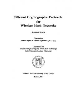
6.1 Protocol Implementation and Simulation The simulations for the relative performance appraisal of the proposed DRABR (Dynamic Resource Allocation with Bandwidth Renegotiation) strategy have been done via a C++ discrete event simulator developed for the purpose. The inputs to the simulator are characteristics/requirements of the traffic in the network, including the bandwidth requirement for peak QoS and acceptable bandwidth exemption. The output of the simulator includes the blocking probability of the new connection requests and the handoff requests. System Model: The system model comprises of a topology consisting of a cell surrounded by six neighboring cells. The central cell pertains to a main city region and the peripheral cell corresponds to the suburban areas located around the city center. The simulations have been done for a scenario typifying the morning rush hour traffic where the calls from the suburban areas are handed into the busy city area. E.g. the 8.00 am to 9.00 Delhi mobile call traffic consists of a large no mobile calls handing in from the peripheral areas like Noida. Simulation model and Assumptions: The network contains 5 traffic classes 0,1,2,3,4 having the peak QoS bandwidth requirements of 32, 64, 64, 300 and 500 Kbps respectively. The expected connection duration times of these classes has been taken to be 10, 20, 20, 500, 1500 seconds. Classes 4,5 require high bandwidths and they also last longer. This is because in practice, users of high bandwidth connections like video conferencing are typically connected for much longer duration as compared to typical voice connections. The central cell has call capacity of 7 Mbps while for the peripheral cells this figure is 5 Mbps Some other features vis-à-vis simulation model are: The arrival of new connection requests of class τ in each cell is taken to be a Poisson process. The duration of each class τ connection request is selected from an exponential distribution. The duration of a connection is selected when it first enters the network. Once determined, 39
its value is fixed until the connection expires. The base station does not use this information to make any decisions because in practice exact duration of a connection will not be known to the network. The residence time of a class τ connection in a cell is chosen when the connection starts and when it incurs a hand off. Consider a connection which enters a cell at time v, that is it started in the cell at time v or it incurred a successful handoff into the cell at time v. Let u’ be the selected completion time for the connection. First a random number w if generated from n exponential distribution. If v+w>u’, ten the connection completes in the cell at time u’. Otherwise t incurs a handoff out of the cell at u+w. Since in practice a base station will not know the exact time of completion of handoff of a connection, this is assumed to be unknown to the base station. The connections in the cells peripheral to the central cell (which is the “hotspot” since it has a flurry of mobile connection traffic) incur a handoff into the hotspot with a conditional probability 0.6. The hotspot does not incur a handoff into any other cell. Therefore a connection terminates in the hotspot on expiry of its connection duration time of cell residence time whichever is smaller. This is a reasonable assumption according to the simulation model that we have adopted. It is assumed that each traffic class type can sustain a bandwidth exemption of 20%. A completely general topology can be visualized as the superposition of the “hotspot” topology employed in our simulations. Consider this set of a hotspot cell surrounded by six less active cells. Then in a network consisting of a large number of cells can be seen as the superposition of such hotspot windows centered at each cell of this network.
40
Relative Performance Appraisal: The performance of the proposed DRABR strategy is assessed with respect to the EXPECTEDMAX and Fixed(5%) strategy. Some of the results pertaining to the performance analysis of the proposed protocol are given below. The complete details are included in appendix as part of B.Tech Project-1 report. 0.45
0.4
probability of New Connection Drops
0.35
0.3
0.25
Series1 Series2 Series3
0.2
0.15
0.1
0.05
0 1
2
3 Class Type
Series 1:DRABR Series 2:EXPECTEDMAX Series 3:Fixed (5%)
Figure 6.1
41
4
5
0.08
0.07
Probability of Dropping a Handoff Connectio
0.06
0.05
Series1 0.04
Series2 Series3
0.03
0.02
0.01
0 1
2
3 Classes of traffic
Series 1:DRABR Series 2:EXPECTEDMAX Series 3:Fixed (5%)
Figure 6.2
42
4
5
_____ -.-.-.-. ------
DRABR EXPECTEDMAX Fixed (5%)
Figure 6.3
43
_____ -.-.-.-. ------
DRABR EXPECTEDMAX Fixed (5%)
Figure 6.4
44
_____ -.-.-.-. ------
DRABR EXPECTEDMAX Fixed (5%)
Figure 6.5
45
_____ -.-.-.-. ------
DRABR EXPECTEDMAX Fixed (5%)
Figure 6.6
46
_____ -.-.-.-. ------
DRABR EXPECTEDMAX Fixed (5%)
Figure 6.7
47
_____ -.-.-.-. ------
DRABR EXPECTEDMAX Fixed (5%)
Figure 6.8
48
_____ -.-.-.-. ------
DRABR EXPECTEDMAX Fixed (5%)
Figure 6.9
49
_____ -.-.-.-. ------
DRABR EXPECTEDMAX Fixed (5%)
Figure 6.10
50
_____ -.-.-.-. ------
DRABR EXPECTEDMAX Fixed (5%)
Figure 6.11
51
Chapter 7 Scheduling Proposals for Wireless ATM The scheduling policies described in the earlier chapter were designed for the wired networks. The delay bound and the fairness that was guaranteed by these policies can only be achieved in a wired network. These bounds cannot be directly applied to wireless scenario. This is because a wireless network suffers from channel errors. These errors which occur because of fading and interference are location dependent and degrade the performance of the network. As a result of these errors a session may receive less service than it is supposed to, while another channel may receive more service than its fair share. Thus while a policy may guarantee fairness in an error free environment, it may not be able to do so in an error prone wireless channel In a wireless environment, some mobiles may not be able to send data because of channel error, while other hosts may have error free channel and can transmit data. If an algorithm is work conserving, it may not be able to guarantee short-term fairness since only few of the channels can actually send data and are therefore eligible for scheduling. However it may be possible to achieve long term fairness by compensating the error prone channel for its lost service. This can be done by allowing it to temporarily receive more service than its normal share. However if the session is allowed to take the entire bandwidth available the QoS of the error free sessions may suffer. Thus the compensating mechanism must not degrade the performance of the error free sessions, while simultaneously making up for the lost services of the session in error. To compare the performance of scheduling algorithms in a wireless scenario four generic properties were proposed in [5]. These are: 1. Delay Bound and Throughput Guarantees: The delay and throughput bounds for error free sessions are guaranteed and should not be affected by the sessions in error.
52
2. Long Term Fairness: If a session becomes error free then over sufficient period of time it should recover all its lost services. This is effect requires the algorithm to achieve fairness in case all session becomes error free which is equivalent to a wired scenario. 3. Short Term Fairness: The difference between normalized services received b any two error-free sessions during a time interval should be bounded. 4. Graceful Degradation: This implies that a session which has received more service than its share should give up only a fraction of its service to provide for compensation. The sessions are classified as leading, lagging and satisfied. A session is leading if it has received more service than it would have received in an ideal error free system, lagging if it has deficit of service and satisfied if it has received exactly same amount of service. In order to account for the service lost or gained, a reference system S’ is associated with every system S. Thus a session is classified as lagging or leading with respect to this reference system S’. Whenever a session is selected in S’ the packet at its head of queue is transmitted. However it may not be possible to do in S since the corresponding session may be in error. Thus the scheduling decisions are made in S ’and its virtual time is updated even if in the actual system the packet may not be sent. An additional parameter called lag is used to keep track of differences between the service received in S’ and the service received in S. Therefore a lagging session has lag which is positive, a leading session has lag which is negative and a satisfied session has lag of zero. Since the algorithm is work conserving it must maintain the following invariant: ∑ i ∈ Α lagi The algorithm selects a session with minimum virtual time in S’. If that session is not leading and can send packets, then the packet at head of queue is sent and its virtual time is updated as follows: Vi = Vi + Lik /Ri where Lik is the length of the kth packet of session ‘i’ and Ri is the rate of session i. however if the session is not leading or cannot send, we search for a session j with the largest
53
normalized lag that can send packet. that is when additional service is available we try to compensate the session that is lagging most. The virtual times or tags of session i are however adjusted and the lags of the two sessions i and j are adjusted. The lags are adjusted to indicate that session i has given up some service and session j has received some additional service Now if a session i with a negative lag wants to leave the active set, the lag is distributed among the remaining active sessions as follows: lagj = lagj + lagi (rj / ∑ k∈A rk )
However a session with a positive lag is not allowed to leave the active set until it has given up all its lead. This is because if the lead history is erased the lagging sessions may not be able to regain their entire lost service. If however there are no active sessions to take up the lead the algorithm advances the virtual time using a dummy packet so that all active sessions can chosen by the server in correct order. Thus this way long-term fairness is ensured. Also an error free session is always guaranteed its fair share, thus there is delay bound for an error free session. The complete algorithm called “Channel Condition Independent Packet fair Queuing (CIF-Q) is given below[5]: On session ‘i’ receiving packet p enqueue (queuei , p) If (i ∉ Active Set) Add ‘i’ to Active Set; Initialize lagi = 0; On sending current packet Select session ‘i’ with minimum virtual time If (lagi >= 0 and (i can send))
// session ‘i’ non-leading and can send
p = dequeue (queuei ) vi = vi + p.length / ri Else j = max lag(i) {k∈Active set and can send} If (j exist)
54
p = dequeue (queuei ) vi = vi + p.length / ri lagi = lagi + p.length lagi = lagi - p.length If (i ≠j and empty (queuej) and lagj >=0) leave (j) Else
// there are no active sessions ready to send vi = vi + δ/ ri If (lagi < 0 and empty (queuej )
// ‘i’ is leading and unbacklogged
j = max lag(i) {k∈Active set} lagi = lagi +δ
// forced compensation
lagj = lagj -δ If (lagi >= 0 and empty (queuei ) ) leave (i) leave (i)
session ‘i’ leaves
Remove ‘i’ from Active Set For (j ∈ Active Set) lagj = lagj + lagi .rj /∑ rk
// update lags of existing sessions
While the above algorithm tries to take into account the wireless channel errors it ignores the wide range of characteristics which ATM traffic will have. The classes of traffic defined by ATM forum and described in section 2.2 have varied QoS requirements. Thus while the scheduling algorithm tries to improve the performance over a wireless channel by compensating the session in case of error, the amount of compensation desired may depend upon the class to which the session may belong. While the CBR traffic requires tight bound on delay, and throughput, the UBR and non-real time VBR have no bounds at all on the delay achieved by these sessions. Thus a scheduling policy that takes into account the
55
variety of QoS parameters of the ATM classes and provides differentiated services and compensation would be desired. To account for this the scheduling algorithm divides the schedules the packets belonging to different classes into hierarchy of priority classes. The ATM QoS parameters are mapped to corresponding weights to maintain the QoS guarantees. At each level or class the scheduling scheme is used in order to maintain the required QoS. The base station scheduler assigns the traffic flows to the channels according to a hierarchy of priorities. The higher priority is for CBR and then for real time VBR. This is because these classes require strict bound on their throughput and delays. These delays and throughput bounds are satisfied through the use of above described scheduling algorithm. The third and fourth priority are given to the system that require certain guaranteed bandwidth but are not constrained by the tight delays. Such classes include non-real time VBR and ABR. These flows do not require extensive fair queuing algorithm since they are non-real time. Therefore these classes use recirculating FIFO for scheduling. This is because these flows are sensitive to loss. Since packets cannot be dropped when the flow detects an error, we recirculate the slot for a later time when the channel is good. This is done by keeping the incoming packets in a separate queue and using the FIFO to reserve slots for head of line packets. Incoming data is added to the per-flow queues. Slots are added to the queue with the pointer to the flow queue as required by the scheduler. If the FIFO head of line slot must wait because of channel error, it is entered into the back of the queue, reserving space for later transmission. Once the channel is good the first slot in FIFO is used to get the head of line packet in the flow’s queue and transmit it. This provides for the wireless compensation without packet loss. The lowest priority is the UBR traffic and does not require any guarantees in either bandwidth or delays. Therefore this class is scheduled according to the order in which the packets arrive. The Medium Access Protocol based on this kind of scheduling was developed and the details are given in following chapter.
56
Chapter 8. Medium Access in Wireless ATM: Models and Proposals A Medium Access Protocol was developed using a discrete event simulator written in C++. The simulator is written in a modular form, which enables us to study the impact of individual features on the overall performance of the network.
8.1 Frame Structure A transmission slot consisting of 1500 bytes is broken into four distinct phases. The first phase (708 bytes) is the acknowledgement of the uplink packets followed by the downlink transmission of PDUs (protocol Data Units each of 56 bytes). The second phase (48 bytes) is the request access period. This consists of the real-time request access slots and the non realtime request access slots. Mobiles access these slots using S-ALOHA. The third phase (60 bytes) is the probe and the uplink slot allocation period. The scheduler allocates the slots for various mobiles to transmit. It also probes the channel during this phase to check if the allocated mobile is able to transmit the packets. The fourth phase (684 bytes) is the actual transmission of packets. The complete frame structure is shown below:
Downlink Transmission
PHASE 1
Request Access
PHASE 2
Transmit Permissions
Uplink Transmission of Packets
PHASE 3
PHASE 4
Figure 8.1 Frame Structure
57
8.2 Mapping ATM QoS Parameters To schedule packets within a particular class , the specific levels of ATM quality of Service needs to be mapped into individual weights for used by the MAC. These weights are determined by the QoS algorithm, and depend on the type of traffic being used and the QoS parameters requested at the connection set up. The algorithm for mapping traffic classes into weights can be rephrased into three parameters for each traffic connection. Bandwidth must be reserved in order to satisfy the cell rates at call admission. The weights must be assigned for the scheduling algorithm in order to satisfy delays; and the buffer must be allocated in order to guarantee that a flow will not lose data. For CBR connections the PCR (Peak Cell Rate) translates directly into a percentage of bandwidth. The max CTD (Cell Transfer Delay) can be used to find the necessary weight. The ΦCBR is inversely proportional to the desired weight (ΦCBR = 1/max CTD) More precisely we can normalize the weight as ΦN = ΦCBR / ∑ Φj ∀ j ∈ Set of CBR connections For VBR connections, the bandwidth requirements are based on SCR (Sustainable Cell Rate) The weights are again inversely proportional to the max CTD (Cell Transfer Delay). The weights are normalized accordingly and are given by: ΦN = ΦVBR / ∑ Φj ∀ j ∈ Set of VBR connections For the non real time VBR, ABR and the UBR there are no delay bounds, although throughput guarantees do exist for the non real time VBR. However since the scheduling mechanism for these is either Recirculating FIFO or a simple FIFO queue the weights are not applicable for these classes. The delay bounds and buffer requirements for these classes are dependent on the QoS required and therefore would be a function of the respective QoS parameters
58
8.3 Buffer Calculations and Delay Bounds for Various Classes As described in the frame structure the first three phases of the MAC protocol consists of downlink transmission of acknowledgements, request access and probing channel and transmission permissions. The actual packets are transmitted only in the fourth phase. Since the inflow of packets in each queue continues even during the first three stages the delay constraints and the buffer required by each class in dependent on the time of first three phases. For simplicity we call the first three phases as pre transmission phase and denote it by p-t-p. The buffer requirement for CBR includes the number of packets that would arrive during the pre transmission phase and the previous Frame length (FL) duration. Since the packets arrive at PCR (Peak Cell Rate) for this interval, and since they are served with highest priority, the amount of buffer space allocated is given by: QCBR = 1+(FL + p-t-p)*PCR For VBR connections the buffer lengths are decided by the SCR (Sustainable Cell Rate), MBS (Maximum Burst Size) and PCR (Peak Cell Rate). Since the packets can arrive at PCR for utmost MBS and for remaining time at SCR only the buffer length is given by: Qrt-VBR = MBS + (FL + p-t-p)*SCR – (MBS / PCR)*SCR + (∑QCBR)*SCR/C where C is the link Bandwidth. The First term accounts for the MBS that comes during the time the scheduler is serving other queues. Assuming that MBS comes in time less than the time next transmission of packets take place, the second term accounts for the packets that come during the remaining time. Since they would be coming at SCR instead of PCR, corresponding rates are used to calculate the buffer. The third term accounts for the time the scheduler takes to service the packets of CBR queue.
59
For the non real time VBR, the expression of the buffer length remains same except that now the time required to serve real time VBR packets will also be included. The expression for buffer length is given as: Qnrt-VBR = MBS + (FL + p-t-p)*SCR – (MBS / C)*SCR + {(∑QCBR) / C + (∑Qrt-VBR) / C}*SCR For the ABR, since only MCR (Minimum Cell Rate) is required the buffer required would be given by: QABR = {(∑QCBR) / C + (∑Qrt-VBR) / C + (∑Q nrt-VBR ) / C}*SCR Since the UBR traffic is insensitive to loss the amount of buffer required is not of much concern. To calculate the delays seen by the head of line packets we note that the algorithm is such that the CBR traffic is served first, followed by the rt-VBR, then nrt-VBR, then ABR and finally UBR. Thus the delay seen by the head of line packet in CBR queue would be minimum and for UBR would be maximum. to calculate the delay bound for a CBR connection we note that each CBR connection is served according to its normalized weight defined in previous section. Thus the delay seen by a head of line packet would be: DCBR = LP {∑ΦCBR/Φj}/C + FL + p-t-p where LP is the length of the packet, C is the link bandwidth and the second term includes the time for the first three phases of the frame structure. For the second level, which is real time VBR there is an additional delay due to the higherpriority traffic. Traffic must wait for the higher level queues to completely drain before gaining access. The delay must also account for the incoming traffic at the higher level. This leads to an effective reduced rate at this level. The delay incurred by the first packet in VBR stream is therefore given by:
60
Drt-VBR = {LP*(∑Φrt-VBR/Φj)/C + ∑QCBR/C + FL + p-t-p} / (1-∑PCRj/C) Since the other three classes have no bounds on the delay requirements, the delay bound for them is therefore unnecessary. These levels are just served by FIFO.
8.4 Traffic Modeling The traffic model used for modeling CBR traffic consists of a packet generator, which generates packets after a fixed interval of time. The inter arrival time between generation of two packets is given by the inverse of the PCR (Peak Cell Rate). This generator clearly models the CBR traffic. For modeling traffic generated by other classes, it is required that a model that simulates the bursty nature of such classes should be used. This can be done by assuming the inter-arrival time to be independently and identically distributed according to Pareto distribution. The Pareto distribution is a distribution with memory, a heavy tail and strong burstiness. Depending upon the value of one of its parameters it can have infinite mean and infinite variance. For a Pareto distribution, a shape parameter ‘a’ and a location parameter ‘k’ are used. the cumulative probability distribution function for a Pareto distribution is given by: F(X ≤ x) = 1 – (k/x)a
where k, a ≥ 0 and x ≥ k
In this expression ‘k’ is the minimum inter arrival time. It is taken to be the inverse of PCR (Peak Cell Rate) for the Available Bit Rate (ABR) and the Unspecified Bit Rate (UBR). It can be shown that if a