PROVIDING AN ENVIRONMENT TO TEACH DSP ALGORITHMS Jos´e Vieira, Ana Tom´e, Jo˜ao Rodrigues Departamento de Electr´onica e Telecomunicac¸o˜ es da Universidade de Aveiro Instituto de Engenharia e Electr´onica e Telem´atica de Aveiro Aveiro, Portugal
[email protected],
[email protected],
[email protected] ABSTRACT Teaching DSP concepts and algorithms can be very frustrating because students don’t realize how to apply the concepts to solve real problems. Most of the DSP courses avoid the implementation of real-time DSP algorithms because it is a time consuming task. To minimize this drawback we developed a hardware expansion for the DSKC3X. We also have implemented a software framework that allows students to easily debug real-time DSP’s algorithms. We also present and discuss the syllabus of an elective course targeted to the Electronics and Telecomunications diploma at the University of Aveiro. 1. INTRODUCTION There are an increasing number of Digital Signal Processing courses using the TMS320C31 DSK, and there is also a very good support for a course preparation which are the books and articles of Chassing [1, 2, 3]. We found that these courses are introduced at different levels in Electrical Engineering Diplomas. Some of them use the DSK on introductory courses while others introduce it after at least one course about digital signal processing [4, 5]. On the first approach the student is never asked to program the processor. The main idea is to got real-time demonstrations of some DSP algorithms taught in the course. The second approach joins the DSP algorithms (that might be taught in a previous course), with an introduction to signal processor architectures and real-time programming concepts in order to accomplish laboratory projects. The Electronics and Telecommunications diploma at the University of Aveio is a five years long diploma organized into semesters and comprises three mandatory courses on Signal Processing: two basic (Signals, Systems, Transforms and Filter Design) and one advanced course (multirate and adaptive filters). During these courses the students use Matlab to study signals and systems concepts or, even to solve several tasks: to identify a phone number in a DTMF sequence, to compress a voice signal using a two-band filter bank, etc.
In spite of digital signal processing theory background, the development of a real-time application on a DSP requires skills and tools that are not taught in this mandatory courses. Then we propose an elective course (12 weeks, 4 hours) where concepts related to the implementation of a DSP algorithms are taught. There are a large number of concepts that the students have to be introduced to, before put a DSP algorithm to work. In order to fit the time schedules for learning the tools, compatible with the course duration we decided to extend the TMS320C31 DSK hardware and to develop a software framework to simplify real-time debugging. So, using this platform we intend to teach the main features of DSP architectures as well as to improve the students debugging skills while some very simple DSP algorithms are developed. During the last 4 weeks of the semester, the students should be able to achieve their own projects running without much assistance from the instructor. 2. THE LABORATORY ENVIRONMENT There are several constraints to use the DSKs in real-time projects. The students have to deal with some obstacles: the new instruction set (such as block-repeat, parallel instructions, and circular addressing), time constraints, assessing the input-output devices and so on. Even when the problem is quite known, there are some debugging skills that must be improved in order to identify the problems that might arise during the project development. The TMS320C31 DSK is a very low-cost platform but it has several limitations to be used directly in a class laboratory. These limitations are mainly related with the analog input/output interface and the amount of memory available. The input/output interface is quite appropriate for voice processing but in a debugging scenario only having voice input and output might not be very helpful. The internal memory is short for very simple applications like echo generation where a very long delay line is required, or to read/write a long segment of data for debugging purpose. To overcome this limitations, the DSK hardware was improved with
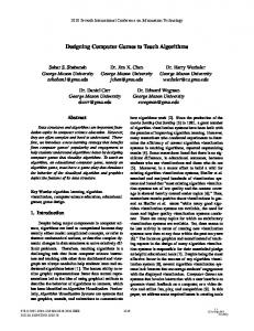
Fig. 1. In this picture we can see the two expansion boards developed for DSKC31. The digital expansion board is at the bottom and the analog expansion board on the top left. two main goals: simplify the experiments and transform the DSK into a stand-alone demonstrator of DSP algorithms. As we can see in figure 1 we added two different boards to the DSK: a digital board and an analog board (fig. 1). 2.1. The Digital Expansion Board In figure 2 we can see a detailed view of the digital expansion board with the main features marked: • The EPROM allows the implementation of standalone DSP applications; • The 128kbytes of zero wait state SRAM for memory demanding applications; • The reset circuit has a DIP switch to select the booting in three differen ways: from the serial port, from the EPROM, or from the internal ROM;
Fig. 2. This board is a piggy-back board for the DSK expanding its capabilities. With the EPROM is possible to develop autonomous applications and the expansion ports ease the implementation of future expansion hardware. the course laboratorys the students can also use the expansion port 2 to perform simple hardware experiments without damaging the DSK. In the signature web page1 it is possible to download detailed information about this expansion board such as schematics, PCB layouts and source code. 2.2. The Analog Expansion Board The analog expansion board (figure 3) was developed to simplify the connection of common analog hardware such 1 http://www.ieeta.pt/˜vieira/tmh
• The expansion port 1 is unbuffered and its purpose is to connect permanent expansion boards. This expansion port provides the 32 bits data bus, all the control signals, the bus address and some address decoded signals to allow simple memory mapping of digital circuits; • The expansion port 2 is buffered and provides 8 bits data bus and some address and control signals. The address space is also decoded allowing minimum hardware glue for digital circuits interface.
With the expansion port 2 it is possible to control, ADC’s and DAC’s, perform digital I/O for external devices control, etc. To provide a simple user interface with the DSP in autonomous applications a two line LCD display with three push buttons was built for this expansion port. During
Fig. 3. This analog expansion board allows the realization of experiments in the laboratory in a flexible way. It also provides several types of input and output plugs.
between three different modes of operation only changing two assembly flags (AICIO and BUFIO):
Cap. Mic.
Din. Mic.
+
• Normal mode BUFIO=0 and AICIO=1: input and output from the AIC and the aquisition interrupts enabled;
IN
BNC DSK BNC
AUX
BNC
OUT
• Debug step-by-step mode: BUFIO=1 and AICIO=0: input and output from memory and the aquisition interrupts disabled; • Debug real-time mode BUFIO=1 and AICIO=1: input and output from the AIC and stored in memory and the aquisition interrupts enabled.
Phones
Below are some of the code lines of the software framework involved in the real time debugging: Fig. 4. Block diagram of the analog interface for the DSKC30 with several analog interfaces. as microphones and oscilloscopes. It permits the connection of up to three summed analog inputs: a dynamic microphone, an electret microphone and a BNC plug that allows the connection to a function generator. This board also has one analog output with two connectors: a headphone jack and a BNC plug. In figure 4 this architecture is described in the form of a block diagram. For instance, during the labs, the students have used the summed analog inputs (figure 4), with a sinusoid and a voice signal to perform experiments like removing the sinusoid from the input signal. The BNC output was used to visualise the output signals on the osciloscope. 2.3. The Software Environment Real time digital signal processing application always requires a great expertise on the architecture details of the DSP. Debugging real time algorithms is a challenge task even for experienced programmers. To take advantage of all the hardware structure as well as to guide the students during the learning process a software framework was developed with two main goals: • Hide the complexity of the initialisation tasks: DSP and AIC initialisation, timers and serial ports configuration, etc. • Provide a simple but effective way to debug real time algorithms on the C31.
In real-time processing, due to interrupts, it is impossible to use the step-by-step debug approach, making very difficult to check the correcteness of the algorithm. To overcome this problem our software allows the user to choose
AICIO .set 1 ; AIC debug flag BUFIO .set 0 ; Buff debug flag .if AICIO Call the AIC initialisation Enable the AIC aquisition interrupts .else Initialise BufferIN and BufferOUT Do not enable the AIC aquisition interrupts .endif . . call GetSamp ; In -> R2 ;-----------------------------------;== Start your code here == ;-----------------------------------;-----------------------------------;== End of your code == ;-----------------------------------call PutSamp ; R2 -> Out . .
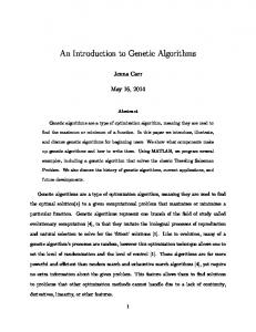
The processing is done in a sample-by-sample way, using an interrupt driven architecture. To get a new sample from the input the sub-routine GetSamp should be called, and to send the result to the output, the sub-routine PutSamp is called. Those routines have different assembled versions acording to the debug flags. The student has only to write the processing code in-between the calls to this subroutines. To conclude, it is possible to generate three different assembled versions of the program without any change on the user source code. Each version should correspond to a different phase of the software development. During the course for every assignment the students are encouraged to follow these three different phases: During the first software development phase the students work on the step-by-step debug mode configuring the program to receive input data from the input buffer (BufferIN)
Bu f fer IN
A lgorith m
B uf fer OUT
BU FIO =1 AIC IO =0
Weeks 1-4
a)
A/D
A lgorith m
D /A
5-8
b) Bu f fer IN
A/D
BU FIO =1 AIC IO =1
B uf fer OUT
A lgorith m
D /A
BU FIO =0 AIC IO =1
c)
Fig. 5. Changing the debug flags (BUFIO and AICIO) the source and the destination of the data is changed.
9-12
Theoretic Lecturers - DSK Environment - C31 architecture - Most common instructions - AIC configuration - DSP Haravd architecture - Data paths - DSP Arithmetic - Memory architecture - Addressing modes - Memory and pipeline conflicts - Interrupts handling - VLIW architectures - MMX technology
Laboratory 1st Exp. - Demonstration of the aliasing effect 2nd Exp. - Sinusoid gererator with an IIR filter 3th Exp. - Implementation of a FIR filter 4th Exp. - Implementation of an adaptive FIR filter Projects
Table 1. Schedule of the course. located in the data memory and write the output to the output buffer (BufferOUT) also located in the memory as described in the figure 5 a). During this phase the interrupts are disabled and the students can run the program step-bystep processing a known signal previously loaded to the input buffer, and check the result at the output buffer. In a second development stage, the students switch to the real-time debug mode of operation, (figure 5 b) ), and run the algorithm in real time, storing the acquired input to the input buffer and the output in the output buffer while sending it to the AIC. This debugging mode it is important to check problems with the real time, and is possible to detect a time run out during the program execution. In this running mode, and for a sampling rate of 8kHz, two seconds of data can be acquired and processed before the buffers fill up. Finally the students set the flags to run on normal mode, and check the algorithm running in real time, receiving samples from the AIC ADC and sending the output samples to the AIC DAC, see figure 5 c). The signals stored in the buffers (BufferIN and BufferOUT) can be compared with the results of the same algorithm simulated in the Matlab. To help the students in the process of data transfer between the Matlab and the DSP two simple Matlab functions were developed which take care of data format details. This simple approach improved very much the debugging of the DSP programs, which used to be the most time consuming task of the software development cycle. 3. THE SYLLABUS The course lasts 12 weeks, with 4 hours per week, 2 hours of lectures and 2 hours of Laboratory. During the first 8 weeks, the students are introduced to the C31 architecture and to
the most useful assembly instructions, while some guided experiments are performed in the laboratory classes. During the last 4 weeks, each group (two students) is engaged in the implementation of a different real-time project (see table 1). The first 4 weeks of the course are very demanding, because the students have to be aware with a large amount of new information. However, this way, the students put something to work very soon, and only after that, they become interested in the course. In the laboratory classes the students are introduced to the DSP development environment, and to the DSP assembly language in a guided way. After a brief introduction to the debugging and assembly tools, the students have to do several guided experiences. In the first guided experience, the students only get used with the DSK environment. They run two examples that demonstrate the aliasing effect. Despite its simplicity, this experiment is very impressive for the students. The second experience provides the code for a second order IIR filter that the students should configure in order to have a sinusoid generator. The code of the previous example is analysed in detail during the classes because it contains some of the most useful assembly instructions. In the third experience the students have to write the code for a FIR filter. To verify the correcteness of the code they have to use the strategy described in fig. 5. The fourth experience reuses the code of the FIR filter to build an adaptive filter with the LMS algorithm. With this filter the students are able to adaptive cancel a sinusoidal interference in a voice signal. The second part of the semester involves the complete development of a small DSP project. Each group has to report different steps of the project which are marked inde-
pendently: 1. Specification of the project main blocks 2. Validation of the proposed design with the Matlab 3. Design of the implementation in the DSP 4. Code writing and debugging After each step the students have to submit a brief report to the teacher with the proposed solutions and all the come up problems. This strategy improved very much the software development cycle since the students have a constant feedback from the teacher. To maintain the challenge and exigency of the projects, each year a new set of projects is created. Below is a list of some of the presented projects with a brief abstract: Music synthesis - This project was presented on three different years using alternative algorithm implementations. Table based sinusoid synthesis, FM modulation and wavetables Vocoder of vowels - Using IIR filter to model the vocal tract and the glottal excitation this simple vocoder ilustrates how vowels can be synthesised. Voice scrambler/unscambler - The spectrum of the voice is modified by reversing the frequencies of the spectrum. This result is obtained by SSB modulation; Five band audio equalizer - This was implemented using five second order pass-band IIR filters. The students are encouraged to develop a PC interface to control the equalizer in real time; Echo and reverberation Generator - This is implemented using a delay line with feedback; Spread Spectrum Communication System - Each symbol is coded with a pseudo-random sequence. The receptor detects these symbols with matched filters and peak detectors; Flanger - It is based on the development of a frational delay implemented using Lagrange interpolation; Voice Pitch Detector - This detector uses autocorrelation and peak detection to evaluate the pitch of a voice signal; Digital recorder - This system waits for a signal with sufficient energy and record the input signal to the external memory using A-law.
4. CONCLUSIONS The described environment proved to be very effective on the organization of the course. The hardware expansions allows the students to set up laboratory experiments with reasonable effort. The memory expansion and the software framework provides a debugging environment that simplify the debugging of real time assembly programs. This strategy proved to be very effective for the success of the development of real-time algorithms. The final project is one of the most remarkable aspects of this course, the development of a DSP algorithm and watching the results creates in the student a sense of satisfaction and confidence. From the point of view of the teacher, is very rewarding to see the students interested in understanding DSP concepts. Every year, a questionnaire about the course is done, and the student comments are globally positive. They used to agree on the following positive aspects: • The possibility to contact with real world applications of digital signal processing. • The course should have been taught early in the course, preferably as a mandatory one. • Some digital signal processing theoretic concepts taught on previous courses were finally understood.
They also mention some bad points of the course: • Too many DSP TMS320C31 details to learn. • Programming in assembly language, they would prefer C.
5. REFERENCES [1] R. Chassaing, Digital Signal Processing with C and TMS320C30. Topics in Digital Signal Processing, U.S.A.: Wiley, 1992. [2] R. Chassaing, W. Anakwa, and A. Richardson, “Realtime digital signal processing in education,” ICASSP Conference, 1993. [3] R. Chassaing, Digital Signal Processing - Laboratory Experiments Using C and the TMS320C31DSK. Series on Parallel and Distributed Computing, U.S.A.: Wiley, 1999. [4] L. Moreno and et al., “Digital signal processors for a signal processing laboratory,” IEEE Transactions on Education, vol. 42, pp. 192–198, Aug. 1999. [5] C. H. G. Wright, T. B. Welch, and W. J. Gomes III, “Teaching DSP concepts using matlab and the TMS320C31 DSK,” in ICASSP99, (Phoenix, Arizona), pp. 3573–3576, IEEE, May 1999.