2010 5th International Symposium on Telecommunications (IST'2010)
Proxy Topology Building and Routing in P2P SIP Architectures Pelagie Houngue1, Ernesto Damiani2
Fatna Belqasmi3, Roch Glitho4
Department of Information Technology Università Degli Studi Di Milano Crema, Italy 1
[email protected] 2
[email protected]
Concordia Institute of Information Systems Engineering Concordia University Montreal, Canada 3
[email protected] 4
[email protected]
Abstract— Research activities have recently begun on the integration of Peer-to-Peer (P2P) principles into the Session Initiation Protocol (SIP). We have contributed to these activities by proposing a P2P SIP architecture where the SIP location service is not managed by the P2P overlay but integrated in proxies that run over peer entities in the P2P overlay. Having SIP proxies as first-class entities, raises two important issues: proxy topology building and proxy-level routing. Thanks to proxy topology building, a proxy joining the P2P overlay knows where it should insert itself in the network of proxies. Proxy-level routing enables messages to be routed in the SIP network built by proxy topology building. This paper proposes a novel framework for proxy topology building and proxy-level routing. The framework is general enough to be used on any P2P overlay that meets a minimal set of requirements. Independence from the P2P infrastructure is aimed at supporting seamless integration of multiple SIP communication environments. Our framework relies on an algorithm that builds the network of proxies in a ring and uses its own routing algorithm to route calls. We describe our novel routing algorithm used between proxies on the ring and evaluate its performance through simulation.
Keywords— Peer-to-Peer (P2P) SIP, Proxy, Application level routing, OSPF, Topology building
I. INTRODUCTION The Session Initiation Protocol (SIP) is an IETF (Internet Engineering Task Force) protocol for the establishment, modification and tearing down of multimedia sessions [1]. Its main architectural entities are the user agent client, the proxy, the registrar and the redirect servers. In conventional implementation of SIP, proxies are centralized application layer routers.
978-1-4244-8185-9/10/$26.00 ©2010 IEEE
Research activities have recently begun working on the integration of Peer-to-Peer (P2P) principles into SIP. P2P networks, also called overlay networks, are logical networks built on top of physical networks [2]. Several P2P SIP architectures have been proposed; our own approach [3] is based on the idea of having SIP proxies running on top of peer entities in the overlay, rather than delegating proxy functions to the overlay itself. Independence from the P2P overlay and performance are the key reasons for our choice. Indeed, implementing our own proxies as first-class entities over the P2P overlay enables us to cache client contact information in the proxy. Introducing proxies in a P2P SIP architecture raises two important issues: proxy topology building and proxy-level routing. Proxy topology building is the process that indicates where a new proxy joining the overlay will be inserted in the network of proxies. Proxy-level routing is the process that routes messages in the network resulting from proxy topology building. This paper proposes a novel framework for proxy topology building and proxy-level routing in our proposed architecture. Our framework is P2P infrastructure independent and may be used by any P2P SIP architecture that includes proxies, provided that some basic requirements are met. The paper also presents a routing algorithm specifically designed for our framework, showing that on our topology, it outperforms standard routing algorithms such as Open Short Path First (OSPF). The next section gives an overview of the P2P SIP architectures with an emphasis on our proposed architecture. After that, requirements are discussed. The third section introduces our techniques in some details, while the fourth section discusses the simulation results. Subsequently we provide a short survey of the related work and give the summary and future work.
669
II. AN OVERVIEW OF EXISTING P2P SIP ARCHITECTURES In P2P SIP, the peers’ contact information (i.e. their IP address and port) is stored in the P2P overlay. To communicate with another peer, a SIP client must first discover the contact information of the destination. There are essentially two classes of P2P SIP architectures [4]: those that extend the SIP standard and those that do not. The first class uses extended SIP (e.g. via additional headers [5]) to build and maintain SIP entities over the P2P overlay, and to publish and discover contact information. In the second class, either a P2P protocol itself or standard SIP messages are used. Within the second category, an important distinction regards the SIP nodes that use the P2P overlay to communicate. When all SIP clients run on top of the P2P overlay, SIP clients do not require a SIP proxy: they publish and discover the contact information directly via the P2P overlay. Alternatively, only a sub-set of peers form the overlay. This sub-set can be a set of peers with advanced capabilities or a set of SIP servers (e.g. SIP proxies), and play the role of a proxy toward ordinary clients, providing them, a suitable location service (i.e. publication and discovery of contact information). This choice is at the basis of our previous architecture described in [3]. It models each SIP domain as a P2P group. The SIP registrar of each domain is distributed and represented by a number of sub-set of distributed registrars (SDR) that compose a fully meshed overlay. The overlay includes a single super-node, called a super sub-set of distributed registrars (SSDR). The SSDR acts as an entry point to the overlay. When a client joins the network, it registers to the SSDR, which stores the client contact information in the SDR’s overlay. To initiate a SIP session, the client sends a SIP INVITE message to the proxy. The proxy checks the SDR’s overlay of its domain for the contact information of the destination client. If the information is not found, the proxy multicasts the INVITE request to the other proxies. The proxy that has the right contact information forwards the INVITE to its destination. This architecture meets two key requirements: being independent of the specific P2P infrastructure and keeping the SIP extensions to a minimum. Indeed, the architecture eases implementation and interoperability with legacy systems by not extending SIP messages. In addition, it ensures portability by being P2P middleware independent. It also enables selforganization, especially when nodes join and leave the overlay. III. ADDITIONAL REQUIREMENTS In our previous architecture [3], the proxies were fully meshed. While this situation makes routing straightforward, scalability is a major issue, making the architecture unfit for large-scale deployment. In this paper, we improve our architecture by proposing a topology that scales and a simple yet effective routing algorithm. In the novel architecture the proxies’ fully meshed topology is entirely replaced by a ring topology. The first requirement is that the framework should meet the key requirements of our overall architecture. The new
architecture preserves our initial proposal's properties (independence of P2P infrastructure, SIP extensions kept to a minimum and self-organization). Also, the new framework supports four additional requirements. Firstly, our framework allows recovery from failure, automatically restoring broken routes between the different proxies. Secondly, it provides simple algorithms for topology building and for routing. In terms of topology, the proxies’ topology should be as simple as possible to ensure it can be created and re-organized easily. Regarding routing, simplicity means that the maintenance procedure for the routing tables should be simple, not take much time to converge, and not generate too much traffic in the network. Thirdly, each proxy in a topology should be able to reach any other proxy in the same topology, meaning that the graph formed by the proxies should be connected. A fourth requirement satisfied by our proposal is that the routing protocol provides the basic properties of routing, namely efficiency, optimality, simplicity, robustness, stability, and scalability in the number of proxies. Routing efficiency means that the routing algorithm should always find a path to reach one node (if a path exists). Optimality refers to the algorithm’s ability to always provide the shortest path. The routing table should also be as smaller as possible. Robustness means that the routing algorithm should be able to cope with changes in the topology, including node failure. A stable algorithm reaches equilibrium and stays there. IV. PROPOSED FRAMEWORK In this paper, we assume a single SIP domain. The domain may have many proxies, and each proxy can manage a limited number of client peers. However, our middlewareindependent approach can support handling multiple domains even when they rely on heterogeneous P2P overlays. In this section, we first introduce the architectural principles on which our framework is based, followed by the topology creation. The routing is then discussed and a scenario presented in the last sub-section. A.
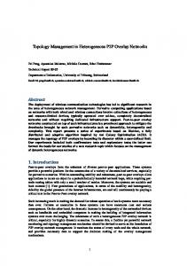
Architectural Principles In this paper, we use the entities Domain Controller (DC) and Group Registrar (GR). The peer nodes are organized in several groups (Fig. 1). Each group is composed of one proxy, one GR and 0 to N clients. The proxies are organized into a ring; we chose a ring topology because it is simple to implement and to maintain. Each domain has a single DC, which is the overlay bootstrapping node. Each node joining the overlay SIP domain should first contact the DC. The DC is responsible for creating and managing the groups, and for creating and maintaining the proxies’ ring. The DC keeps the list of the groups and for each group, it maintains the GR address and the number of clients. For recovery from failure, we select the alternative which consists of putting the recovery functionality in the topology building (instead of in the routing).
670
notifications from them. Subsequently, each of the two neighbors also subscribes to Pi.
P2
Level 2
Single Domain
P1 P3 P4
C1
C4
Level 1
GR1
C5
C3
C2
GR2
GR3 GR4
DC
Figure 1. New proxies network topology in ring
As we shall see, the algorithms used by our architecture for topology creation and for routing are P2P infrastructure independent, thereby ensuring portability. B.
Topology Creation and Maintenance The proxies’ ring is organized following a clockwise direction; a new node is always inserted between the first and the last node in the ring. The first and the last nodes will be the successor to and the predecessor of the new node, respectively. This choice makes new node insertion simple and minimizes the information maintained by the DC. The DC maintains a topology table that includes the first and the last node in the ring. When a new node is inserted, only the table entry corresponding to the last node is updated. Each proxy has also a topology table which contains its successor and predecessor in the ring. We maintain the ring topology by using only SIP messages without needed to perform any SIP messages extension. This fulfills one of our main requirements. We now describe how a new proxy is added to or removed from the ring. 1) A proxy joins the network When a proxy (Pi) joins the network, it sends a SIP REGISTER message to the DC. The DC sends to Pi the address of the GR, the addresses of Pi’s predecessor and successor, and the total number of the proxies in the ring (N), including the new incoming proxy (Pi). This information is sent in the 200 OK SIP message. The DC also forwards the Pi’s registration to the GR. Then, Pi sends a SUBSCRIBE message to the GR to subscribe to events notification, and the GR does the same. Pi subscribes to its neighbors as well, to notify its place in the ring (i.e. as predecessor or successor) and to receive future
2) A proxy leaves the network The leaving proxy (Ni) sends a NOTIFY message to the GR of its group, along with its predecessor (Pr-i) and successor (Su-i), and then unregisters from the GR. If there is at least one client in the group, the GR chooses one client in the same group and sets it as the new proxy (the clients SUBSCRIBE to the GR when they enter the network). The newly-elected proxy will have the same proxy-id as the departing one. It is informed about its new role via a NOTIFY message and it is given its successor (i.e. Su-i) and predecessor (i.e. Pr-i). It then sends a SUBSCRIBE message to its neighbors as in the joining procedure. Next, the neighbors update the address of the proxy in their routing tables. The GR also notifies all the clients in the group about the new proxy, and informs (using a SIP NOTIFY) the DC about the new elected proxy and the departure of the old one. The DC had subscribed to the GR when the GR joined the network. If the departing proxy is the first or the last in the ring, the DC updates its topology table. If there is no client in the group, the GR notifies Pr-i that Ni has left and that its new successor is Su-i. Pr-i subscribes to Su-i and informs it to be its new predecessor. The GR also notifies the DC that Ni has left, and gives Pr-i and Su-i. DC updates its topology table if Ni was the last or the first proxy in the ring. C.
Routing Procedures Each proxy maintains a routing table that includes an entry for every other proxy in the ring. Each entry has three columns: destination (i.e. the proxy to reach), send (i.e. right or left), and distance (i.e. the distance to reach the destination). The distance is computed as the number of hops towards the destination. The ‘send’ column is set to ‘left’ if the shortest path to reach the destination is in the clockwise direction. Otherwise, the column is set to right. This section describes how the routing tables of the different proxies are created and updated. 1) Creation/update of the routing tables when a proxy joins When a proxy (Pi) joins the ring and sends a SUBSCRIBE message to its neighbors, it includes a TTL variable in the message. The TTL is equal to the integer value of: (N/2)-1, where N is the number of proxies in the ring. It is used to control the number of times the information about the new proxy is forwarded inside the ring.
671
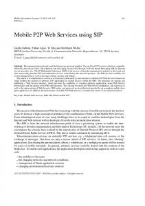
When a neighbor (Ni) receives a SUBSCRIBE, it updates its routing table using the procedure described in Fig. 2.a. Among others, it adds a new entry to its local routing table as follows: destination=Pi; distance=1; send=left (or right, A proxy Pj receives information that a new proxy Pi is added to the ring (via SUBSCRIBE or NOTIFY), with the attributes: new-node=Pi; distance=di; TTL=TTLi; o Pj updates N value: N=N+1 o If D(pj->pi)pk)>=D(pi->pj)) :::: If Pk is now reachable via the new proxy Pi If (D(pi->pk)+1pk): D(pi->pk) += 1:::: update the distance, but :::: keep the same path
-
Else - Switch the ‘send’ column corresponding to pk in the routing table :::: Keep the same distance but specify that Pk is now reachable :::: via the opposite path (not via Pj)
a. The procedure for an existing proxy to update its routing table when a new proxy joins the ring - When a proxy Pi is added to the ring, it gets its successor (Su) and predecessor (Pr). Pi adds Su to its routing table, with ‘send’=left & distance=1.
- When Pi sends a SUBSCRIBE message to its successor, it receives a NOTIFY message including the routing table of the successor (Tsu), and then it updates its own routing table from its successor’s routing table. o For each Pk∊Left(su) • If (D(su->pk)+1) pk)+1 • Else Pi adds Pk to its routing table with a switched value of ‘send’ attribute in Tsu, and with the same distance as in Tsu o For each Pk∊Right(su) • Pi adds Pk to its routing table with the same ‘send’ attribute and distance as in Tsu. b. The procedure for the joining proxy to create its routing table When a proxy Pj receives the news that a proxy Pi has left the ring: with attributes: leaving-node=Pi; distance=di; TTL=TTLi; o If D(pj->pi)pk)>=D(pj->pi)) :::: If Pk is currently reachable via the
depending on if Pi is the predecessor or the successor). If TTL>0, Ni notifies (via a SIP NOTIFY) its other neighbor (i.e. other than the one from which it received the news) about Pi. It sends the following information: new-node=Pi; distance=D(Ni->Pi); TTL=TTL-1; D(Ni->Pi) is the distance between Ni and Pi (in this step D(Ni->Pi)=1). The receiving proxy (Pj) executes the same procedure as Ni (i.e. it updates its routing table and notifies its other neighbor if appropriate) and the procedure is repeated until TTL=0. If a proxy receives the notification twice (from its successor and from its predecessor), it chooses the first path it receives. This will happen if N is even, and the two paths will have the same length. The new proxy creates its own routing table using the procedure described in Fig. 2.b. 2) Update of the routing tables when a proxy leaves When a proxy Pi leaves the ring and there is no client to replace it, its predecessor Pr is notified. Pr notifies its neighbors that Pi has left and the information is propagated inside the ring using the same procedure as for a node joining, by using TTL=(N/2)-1. When a proxy receives the leaving notification, it removes the entry corresponding to Pi from its routing table and recalculates its distances to the other proxies using the procedure in Fig. 2.c. D.
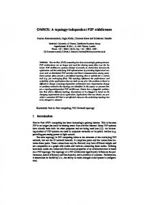
Call Scenario Fig. 3 shows a scenario where a client C1 in group1 is willing to establish a SIP session with a client C2 in group 2. First, the two clients register to their respective GRs. In step 5, C1 sends a SIP INVITE message to its proxy (i.e. P1). We assume that P1 has already found the contact information of C2 (i.e. it knows that it is connected to P2) and that this information is stored in its cache. P1 then checks its local cache, discovers that the request should be forwarded to P2, and sends out the request on its left as per its routing table (the shortest path is going left). P2 first checks its own cache, but it does not include any information about C2. It then asks its GR (GR2) for the contact information of C2 and forwards the request to it. The response is forwarded back to C1 via P2 and P1.
:::: leaving proxy Pi
Group-2
Cache 2 Group-1
8 : checking
Cache 1 ITE 7: INV
6: checking 5 : INVITE
c. The procedure for an existing proxy to update its routing table when a proxy leaves the ring Legend
IFY 9 : NOT
P2
13 : OK
P1
P3
C1
11 : :O
K
IN VI TE
P4
Proxies’ ring 2 : OK 1 : REGISTER
GR1 Figure 3. Call establishment scenario
Figure 2. Routing table creation and update
672
4: OK
C2
1:
¾ D(pi->pj): The distance between Pi and Pj, ¾ Right(Pj) and Left(Pj): The list of the proxies that Pj reaches from its right or its left, respectively ¾ Candidates(Pj): equal to Right(Pj) or Left(Pj) depending whether Pj receives the message (i.e. a proxy is joining or a proxy is leaving) from its right or from its left.
10: OK
12
14: OK
GR2 3 : REGISTER
- Change D(pj->pk): D(pj->pk) -= 1:::: update the distance • For each proxy pm in Candidates ={p, p is a proxy and p∉Candidates} If (D(pj->pm) =N/2) - Switch the ‘send’ attribute corresponding to Pm :: Switch direction o Pj updates N value: N=N-1
V. VALIDATION We used OverSim [9], an open source P2P network simulation framework, to evaluate the proxy topology building and proxy-level routing performance in our architecture. Oversim was built by the Institute of Telematics, Universität Karlsruhe on top of the OMNeT++/OMNEST simulation environment. It includes several structured and unstructured P2P protocols such as Chord, Kademlia and Pastry. Oversim also provides several common functions, including a generic lookup mechanism and a remote procedure call interface, to facilitate the implementation of additional protocols. Another important feature of OverSim is that it provides several models for generating churn (including a lifetime-based churn model supporting different distribution functions) and underlying network topology. The goal of our simulations is to evaluate the performance of our routing algorithm and to show that the general routing algorithms like OSPF [10] are not appropriate to be used on our specific proxies on ring topology. Hence the motivation to propose an appropriate routing algorithm. First, we evaluate and compare the traffic overhead introduced by our algorithm and that generated using OSPF as the routing protocol of our P2P SIP architecture. Second, we compare the convergence time of the two algorithms. The convergence time we measured is the time between the new proxy entering in the ring and the time when all of the proxies participating in the overlay receive the information about the new proxy and update their routing tables. The evaluations show that our protocol outperforms OSPF. We first discuss how OSPF can be used as the routing protocol of our architecture, and then present and discuss the evaluation results. OSPF Simulation on Our Architecture This section describes how we adapted and implemented (on the simulation framework) OSPF on our architecture. In this paper, we only focus on proxy node joining. When a proxy Pj enters the ring, it creates a Link State Packet (LSP) containing its two neighbors and the distance to reach them (1 in this case) and sends it to all of the proxies in the ring. The LSP is sent following the same procedure we described earlier for node joining, meaning that the LSP is sent to the neighbors using a SUBSCRIBE message and the neighbors forward it to all of the other proxies using NOTIFY. Each of the other proxies create a similar LSP and sends it to all of the other proxies (using NOTIFY). After a proxy receives N-1 LSP (i.e. LSPs are received from all other proxies), it computes its routing table using the Shortest Path First (SPF) algorithm. The main difference between this implementation of OSPF and our routing algorithm is about the number of messages exchanged on the ring, in order to allow the correct update of the routing tables when a proxy joins or leaves the P2P SIP network.
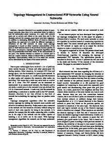
B. Experimentation Results 1) Network load Fig. 4 shows the network load in terms of the number of messages transmitted in the network. The figure clearly shows that OSPF generates more messages than our algorithm. This can be explained as follows: when a proxy joins the overlay, with our algorithm, only the joining proxy sends an LSP to all of the other proxies. In OSPF, an LSP is sent by each of the proxies in the overlay. The difference between the two algorithms becomes more noticeable as the number of proxies in the overlay grows.
Figure 4. Proxy level routing algorithm vs. OSPF network load
A.
2) Convergence Time
Figure 5. Proxy level routing algorithm vs. OSPF convergence time
673
Fig. 5 shows the convergence time of the two routing algorithms (i.e. ours and OSPF) as a function of the number of proxies in the overlay. The simulations are run on top of the Chord P2P overlay middleware. We are fully aware that Chord would not be the first choice for a P2P overlay to support SIP, as Chord’s overlay organization is entirely independent from the SIP-level one. However, running on top of this overlay is a worst-case scenario that shows the flexibility of our middleware independent technique. The results are collected for different numbers of overlay proxies. We can easily observe that the convergence time of our algorithm is much smaller than the OSPF convergence time. This is because more messages are exchanged in OSPF, and each proxy needs to wait until it gets an LSP from every other proxy. Furthermore, each proxy needs to build the entire proxy graph in order to update its routing table. Instead, our algorithm encapsulates the distance between the new incoming proxy and all other proxies in the proxy joining information packet. RELATED WORK VI. We split the related work into two categories: P2P SIP architectures that include both topology building and routing, and general infrastructure-independent routing protocols. In the first category, for the sake of conciseness, we will not consider the class of the existing P2P SIP architectures that extend SIP [5], because we consider compatibility with current SIP standards as key requirement. We will rather focus on the architectures that do not extend SIP. Some architectures in this category are DHT-based [11][12], which breaks the requirement on independence from the P2P infrastructure. Several P2P SIP frameworks proposed to date like P2PNS [7], SIP usage for RELOAD [8] and others are similar to our framework. But those proposals explicitly chose not fill our specific requirements, like the P2P infrastructure independence and non-extension of SIP messages as described in [3]. Infrastructure-independent routing protocols include classic Internet routing protocols such as OSPF and Distance Vector Routing (DVR). These classic protocols meet most of the routing requirements (e.g. efficiency and optimality). However, in the specific case of the topology we propose, they generate more network traffic than the algorithm that we propose with our framework.
VII. CONCLUSION AND FUTURE WORKS We have presented in this paper a novel framework for proxy topology building and proxy level routing on top of a novel P2PSIP architecture we have proposed in recent past. The framework is P2P infrastructure independent and can be used by any P2P SIP architecture that meets a minimal set of requirements. We have described an algorithm that builds the network of proxies in a ring, and a novel routing algorithm that outperforms existing routing algorithms such as OSPF when used on the ring topology. The novel algorithms are
fully described and their performance evaluated via simulations. As future work, we will extend the topology building and routing algorithms to take into account forced departure, wherein the overlay nodes are forced to quit the network, as in case of failure. We are also comparing our framework performances to other existing P2PSIP architectures. Furthermore, we will propose an application scenario allowing multiple SIP domains communication between P2P SIP clients using heterogeneous P2P infrastructures. REFERENCES [1]. J. Rosenberg, H. Schulzrinne, G. Camarillo, A. Johnston, J. Peterson, R. Sparks, M. Handley, and E. Schooler, “SIP: Session Initiation Protocol”, RFC 3261, June 2002. [2]. E. K. Lua, J. Crowcroft, M. Pias, R. Sharma, and S. Lim, “Survey and comparison of Peer-to-Peer overlay network schemes,” IEEE Communications Surveys & Tutorials, Volume 7, No.2, Second Quarter 2005. [3]. P. Houngue, R. Glitho, and E. Damiani, “A Novel Architecture for Peer to Peer SIP”, IEEE Symposium on Computers and Communications (ISCC), June 22-25, 2010, Riccione, Italy [4]. S. A. Ahson and M. Ilyas, “Sip Handbook Services, Technologies, And Security of Session Initiation Protocol”, CRC Press, 2008 [5]. D. Bryan, B. Lowekamp, and C. Jennings. 2007. dSIP: A P2P approach to SIP registration and resource location. IETF draft-bryanp2psip-dsip-00, February. [6]. Kundan Singh and Henning Schulzrinne, “Peer-to-Peer internet telephony using SIP”, NOSSDAV 2005: 63-68 [7]. Ingmar Baumgart, “P2PNS: A Secure Distributed Name Service for P2PSIP”, Proceedings of the Sixth Annual IEEE International Conference on Pervasive Computing and Communications (PerCom 2008), Hong Kong, China, p. 480-485, March 2008. [8]. C. Jennings, B. Lowekamp, E. Rescorla, S. Baset, and H. Schulzrinne, “A SIP Usage for RELOAD”, Internet Draft, draft-ietf-p2psip-sip-05, July, 2010 [9]. Oversim, www.oversim.org, October 2010 [10]. J. Moy, “RFC 2328 : OSPF Version 2”, April 1998 [11]. K. Singh and H. Schulzrinne, “Using an External DHT as a SIP Location Service”, Tech. Report CUCS-007-06, Columbia University, 2006. [12]. H. Schmidt, B. Aksoy, F. J. Hauck, and A. Kassler, “How well does JXTA fit Peer-to-Peer SIP?”. IEEE, Communications ICC_08 proceedings, 2008.
674