WSEAS TRANSACTIONS on CIRCUITS AND SYSTEMS
Ciprian Seiculescu, Ioan Lie, Aurel Gontean
PWM encoding method for wireless communication in sensor networks CIPRIAN SEICULESCU, IOAN LIE, AUREL GONTEAN Applied Electronic Department „Politehnica“ University of Timisoara Bd. Vasile Parvan, no. 2, Timisoara, 300223 ROMANIA
[email protected] Abstract: -. When designing low power sensor with radio capabilities the choice of the encoding for the radio signal can have great impact on performance and implementation requirements. The paper presents different encodings with their advantages and disadvantages, looking at both performance and implementation requirements. Finally the paper presents a proposed PWM encoding and the way that it was implemented and shows that the implementation advantages over other more traditional encoding outweigh the loss in performance. As well the paper presents different implementation methods for transmitters and receivers using the PWM encoding.
Key-Words: - PWM, amplitude modulation, Low power sensors networks, FPGA Prototyping, radio communication In the paper we will present radio communication aspects for nodes designed to work for environmental data collection. In our case the environment is the house. There are many things that are currently monitored in the house like: electricity, water and heat consumption. These things can be monitored automatically by a wireless sensor network and then the data to be centralized and sent to the authorities that are interested in it in order to issue the bills for home automation. One important demand is to reduce the number of wires needed to connect all the sensors as it is very inconvenient to install a large number of wires to create a sensor network. For example, if smart water meters and smart heat meters are installed the state of the meters can be collected by the network and transmitted by some standard network (Ethernet) to the company that sends the bills. The paper describes how we chose and implemented the wireless communication for this sort of sensors and the data collector while at the same time to meet the other constraints imposed for such sensors. Water meters and heat meters for home automation have to be cheep low power devices. Most sensors are built around a microcontroller that has to implement all the logic of the sensor. Such sensors usually have to work for at least ten years on battery and therefore have to be low power. There is little extra hardware that can be added apart from the controller. In this case all the communication
1 Introduction With the advancements in the wireless radio communication and the availability of low power micro controllers a new research field became very popular in the past few years called “Wireless sensor networks”. A wireless sensor network is formed from nodes capable of sensing, processing and communication that allow the network to analyze data in a distributed fashion. There are many applications where data from different places has to be collected and analyzed as a whole to solve a problem and wireless sensor networks are good candidates for this sort of problems. In [11] three classes of applications have been identified as relevant for being implemented with wireless sensor networks. These classes are: environmental data collection, security monitoring and senor node tracking. Environmental data collection refers to collecting data from many points over a long period of time in order to be able to infer some properties about the environment by analyzing the collected data. For the security monitoring application class sensors do not gather information, they are analyzing the information online in order to detect abnormalities. In the node tracking scenario tagged objects are tracked through a region monitored by the sensor network. An example of where this class of application can be used is in logistics companies like UPS [12]. ISSN: 1109-2734
194
Issue 4, Volume 7, April 2008
WSEAS TRANSACTIONS on CIRCUITS AND SYSTEMS
Ciprian Seiculescu, Ioan Lie, Aurel Gontean
transmit the data and therefore violate our low power restrictions. In order to avoid the problem of the UART encoding we turned to an encoding that ensured that we would have a carrier wave for an average of 50% of the transmission time regardless of the data we transmit. An encoding that complies with these specifications is the Manchester encoding, [2, 3] – Figure 2.
protocol has to be implemented in software with limited hardware support only what is offered as peripherals of the microcontroller. Under these constraints we had to optimize the data encoding for the communication protocol in order to be easier to implement in software and still to keep a performance that is close to a more traditional encoding, but which would require some dedicated hardware components.
2. Coding solutions The simples coding and physical layer communication protocol is the one used at the UART transceivers. [1] This is a simple encoding where the bits are encoded by the voltage level and the protocol permits the synchronization of the receiver at the beginning of each byte. Since the transmitter is implemented in software and sometimes the receiver as well, timing is critical and it is very complicated to keep both the transmitter and the receiver synchronized for very long. The UART protocol has the advantage that the transmitter and the receiver have to be synchronized only for the duration of one byte. On the other hand our simple radio transmitter was set for ON/OFF amplitude modulation. This means that if data that contained a lot of zeros has to be transmitted for the duration of those zeros there would be no carrier wave with this encoding – Figure 1.
Figure 2 Manchester coding
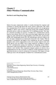
From the electrical point of view the Manchester encoding is ideal, however we had implementation problems. One major problem that we faced with our software implemented versions is synchronization. Synchronizing the receiver with the transmitter is only possible without any extra overhead at the beginning of the data package where code violations can be inserted. After the initial synchronization both the transmitter and the receiver would have to keep a stable operating frequency for the duration of the whole package. Implementing these timing requirements in software is very difficult and the slightest deviation would result in errors at reception even if the signal is not affected by noise and the whole package would need to be retransmitted resulting in a waste of energy. A robust encoding for software implementation should allow the receiver to synchronize with the transmitter more often than just at the beginning of the data package. At the same time the encoding should allow the carrier wave to be on enough time, so that the receiver would not be affected by noise, regardless of the transmitted data. We found that by using a “Pulse Width Modulation” (PWM) to encode the data at the physical layer we could satisfy both requirements. We defined the encoding as follows: a 25% pulse for logical ‘0’ and a 75% pulse for logical ‘1’. This way in the worse case when a lot of ‘0’ are transmitted the carrier wave is on for at least 25% of the time. The other main advantage is that each bit starts with a rising edge which can be used for synchronization at the receiver as shown in Figure 3.
Figure 1 UART coding (up) – the worst case (down)
The lack of carrier wave from the transmitter leads the receiver to drift from the functioning point and start amplifying the noise which compromises the transmission. One solution was to divide the data into nibbles and force some bits to ‘1’ in order to have the carrier wave active for sufficient time. However this would double the time necessary to
ISSN: 1109-2734
195
Issue 4, Volume 7, April 2008
WSEAS TRANSACTIONS on CIRCUITS AND SYSTEMS
Ciprian Seiculescu, Ioan Lie, Aurel Gontean
transmission. We used a 16 bit CRC with the standard CCITT polynomial expression. Except for the data that we needed to add to comply with the requirements of the physical medium we tried to construct the data package to be general in order to use it for any application with sensor networks. Therefore the data package contains a fixed length header that contains the destination address on 8 bits, the source address on 8 bits, an 8 bit field to identify the connection, the length of the data on 8 bits and the CRC code of the header on 16 bits. After the header the data is send and it can have variable size in between 1 and 255 bytes followed by the CRC code of the data field.
Figure 3 PWM signals diagram
As shown in Figure 3 each bit of the transmitted data starts with a rising edge and has a predefined constant period known by the receiver. The only thing that changes is the pulse width. The receiver can synchronize on the rising edge and set its timing to sample at 50% of the period. If the transmitted bit is ‘0’, than the receiver sampling at half the period, will see a ‘0’. The case where ‘1’ is transmitted is similar and the sampled values are actually the bit values and no further processing is necessary. This encoding method proved to be robust because with the synchronization on each bit the timing errors introduced by software implementations of the transmitter or the receiver are not cumulated to the whole package, therefore requiring precise timing. From over experiments that we will present in the chapter 4, we will show that the PWM encoding method is comparable to the Manchester encoding methods and that advantages offered for implementation are greater than the loss in performance as compared to Manchester encoding.
Figure 4 Data package description
3.2 Software implementation We have implemented a software version of the transmitter using a MSP430F417 microcontroller from Texas Instruments. This is a low power microcontroller which is used for many metering applications since it also has an integrated LCD controller. The only hardware support that we used was one of the timers and a compare channel in order to generate the timing from the transmitter. Since metering applications have to be low power solutions the microcontroller was set to work at 1 MHz in order to save energy. In order for the transmitter to work at this clock speed, we could not use the timer interrupt to construct the transmitter code. Instead the assembly written code that emulates the transmitter actively waits on the interrupt flag of the compare channel that was used to generate the timing. The disadvantage of this solution is that the microcontroller has to be active all the time until the whole data package is transmitted, but the advantage is that we have more precise timing without having a dedicated hardware controller as a transmitter. In a similar fashion we implemented a software version of the receiver which we tested on a MSP430F449 microcontroller [17]. We chose this controller because it has a standard UART hardware
3 Implementations. 3.1 Data package description There are three problems that we tried to address when we defined the structure of our data package. One problem was to allow time for the receiver to get ready to receive data. We do this by transmitting 8 bytes with the value 0xAA as a preamble. This way the receiver sees the carrier wave for 50% of the time on average and it should bring the receiver in the functioning point. The second problem was to find a way to delimit the start of the package. For this we chose to transmit a field of 16 bits after the preamble which we called the key. We chose to transmit the value 0xCCCC as the key – Figure 4. The receiver has to wait for the key combination before starting to save the received data and has to ignore any key combinations that appear until the end of the package. The third problem that needed to be solved was to ensure data integrity. We did this by using CRC to detect any errors in the ISSN: 1109-2734
196
Issue 4, Volume 7, April 2008
WSEAS TRANSACTIONS on CIRCUITS AND SYSTEMS
Ciprian Seiculescu, Ioan Lie, Aurel Gontean
interface which we used to connect to a PC in order to collect data. However this is similar with the previous controller which is more popular for simple meters. The algorithm by which the receiver works is presented in the following pseudo code:
As can be seen from the pseudo code a major drawback of a purely software implementation of the receiver is that the controller is always busy waiting to receive the key which marks the begging of a data package and while receiving the data. The problem is that without any carrier wave present the receiver amplifies the noise to logic levels and therefore if the input pin would be set to give an interrupt on change, the interrupt would constantly be triggered. For this reason a purely software receiver implementation has limited practical application. This sort of software implementation can only be used practically if the receiver knows the approximate times when the sensors are transmitting and it only goes into the receiving loop around those moments. Timeouts provide ways to exit the loops in case there is no transmission present in a reasonable time window.
1. loop 2. wait for rising edge and set timer upon detection 3. wait for timer and sample on timer overflow 4. if received pattern matches the key go to 6 5. if expected time to receive data elapsed go to 34 6. end loop 7. set byte counter to header size 8. loop 9. set bit counter to word size 10. loop 11. wait for rising edge and set timer upon detection 12. wait for timer and sample on timer overflow 13. decrement bit counter 14. if byte received go to17 15. if timeout occurred go to 34 16. end loop 17. decrement byte counter 18. if data received and CRC test is successful go to 20 else go to 34 19. end loop 20. set byte counter to data size 21. loop 22. set bit counter to word size 23. loop 24. wait for rising edge and set timer upon detection 25. wait for timer and sample on timer overflow 26. decrement bit counter 27. if byte received go to 30 28. if timeout occurred go to 34 29. end loop 30. decrement byte counter 31. if data received and CRC test is successful go to 33 else go to 34 32. end loop 33. set flags to indicate correct reception and return 34. set flags to indicate the occurred error and return ISSN: 1109-2734
3.3 Hardware implementation To test a hardware implementation, we used an FPGA platform based on Cyclone II device from Altera. We also used the Nios II processor that Altera offers for their FPGAs to build out system. The idea behind the hardware implementation was to create a data collection device for intelligent meters, which could collect the data from the sensors over radio and relay to a central database over Ethernet. In order to offload the processor as much as possible we implemented the physical level protocol and most of the data link level protocol in hardware. A simplified diagram of our test system is presented in Figure 5.
Figure 5 The block diagram of test system
In order to use the TCP/IP stack we programmed our application using MicroC/OS-II real time kernel. In this case it was useful to move as much of the radio transceiver protocol in hardware and to use some FIFO buffers in order to have more relaxed real time constraints
197
Issue 4, Volume 7, April 2008
WSEAS TRANSACTIONS on CIRCUITS AND SYSTEMS
Ciprian Seiculescu, Ioan Lie, Aurel Gontean
to hold the received byte. To reduce the number of necessary connections the processor can read the data serially, using a simple sample and shift protocol.
The whole design including the processor and other necessary peripherals was fitted in fewer than 5000 logic cells. For a more precise report see Figure 6.
3.4 RF modules The radio transmitter and receiver modules were build around two dedicated circuits: the TH72032 ASK transmitter and the TH71111 FSK/FM/ASK single-conversion superheterodyne receiver. The TH72032 ASK transmitter IC is designed for applications in the European 868 MHz industrialscientific-medical (ISM) band, according to the EN 300 220 telecommunications standard. It can also be used for any other system with carrier frequencies ranging from 850 MHz to 930 MHz. The transmitter's carrier frequency fc is determined by the frequency of the reference crystal fref. The integrated PLL synthesizer ensures that carrier frequencies, ranging from 850 MHz to 930 MHz, can be achieved. This is done by using a crystal with a reference frequency according to: fref = fc/N, where N = 32 is the PLL feedback divider ratio. As depicted in figure 8 the TH72032 transmitter consists of a fully integrated voltage-controlled oscillator (VCO), a divide-by-32 divider, a phasefrequency detector (PFD) and a charge pump (CP). An internal loop filter determines the dynamic behavior of the PLL and suppresses reference spurious signals. A Colpitts crystal oscillator (XOSC) is used as the reference oscillator of a phase-locked loop (PLL) synthesizer. The VCO’s output signal feeds the power amplifier (PA). The RF signal power can be adjusted in four steps by changing the value of resistor RPS or by varying the voltage at pin PSEL. The open-collector output (OUT) can be used either to directly drive a loop antenna or to be matched to a 50Ohm load. Bandgap biasing ensures stable operation of the IC at a power supply range of 1.95 V to 5.5 V. The PLL transmitter can be ASK-modulated by applying a data stream directly at the pin ASKDTA. This turns the internal current sources of the power amplifier on and off and therefore leads to an ASK signal at the output. The mode control logic allows two different modes of operation as listed in the following table. The mode control pin ENTX is pulled-down internally. This guarantees that the whole circuit is shut down if this pin is left floating. After enabling the transmitter by the ENTX signal, the power amplifier remains inactive for a time ton, the transmitter start-up time. The crystal oscillator starts oscillation and the PLL locks to the desired output frequency within the time duration ton. After successful PLL lock, the LOCK signal turns on the
Figure 6 Hardware implementation report
However in order to make low cost sensors with receiver capabilities a hybrid solution can be used. It is enough to implement in hardware the “Receiver logic” and to implement the protocol in software. This way the controller is interrupted only when the key is detected or when a byte is received. The “Receiver logic” block only takes 58 logic cells. Such a receiver together with some additional logic for communicating with a microcontroller could be fitted in a low power CPLD like the ones from the Cool Runner II series from Xilinx with 128 elements. A schematic of such a receiver module is presented in Figure 7.
Figure 7 Schematic of a receiver module
As can be seen in the diagram the simple receiver that can be used to offload the microcontroller from doing active waiting contains very few parts. It requires an edge detector that can be implemented with two flip-flops and some gates, a timer large enough to implement the half period timeout, a 16 bit shift register to sample and assemble the data, comparer with a constant (the key) a bit counter to identify the bytes from the bit stream and a register ISSN: 1109-2734
198
Issue 4, Volume 7, April 2008
WSEAS TRANSACTIONS on CIRCUITS AND SYSTEMS
Ciprian Seiculescu, Ioan Lie, Aurel Gontean
4 ROI
XTAL
PA
%32
1 7 OUT antenna
matching network
PFD
3
XOSC
low voltage detector
VCO
- CP +
XBUF
CX1
2
8 VEE Figure 8 TH72032 ASK transmitter
ENTX
LOCK
ASKDATA
ton
RF carrier
Figure 9 Timing diagram for ASK modulation
MIX1
IN_LNA
LNA
31
7
IF
X
8
MIX2
9
10
VEE_IF
6
VCC_MIX
5
IF1P
4
VEE_MIX
3
IN_MIX1
2
1
OUT_LNA
The TH71111 FSK/FM/ASK single-conversion
11
12
13
21
14
15
IN_DEM
PLL
mode control
ASKDTA
5
6
OUT_IFA
ENTX
PSEL
VCC_IF
VCC
FBC2
RPS
FBC1
superheterodyne receiver IC is designed for applications in the European 868 MHz industrialscientific-medical (ISM) band, according to the EN 300 220 telecommunications standard. It can also be used for any other system with carrier frequencies ranging from 800 MHz to 930 MHz With the TH71111 receiver chip, various circuit configurations can be arranged in order to meet a number of different customer requirements. In ASK configuration the RSSI signal is fed to an ASK detector, which is constituted by the operational amplifier. This receiver allows a higher degree of image rejection achieved in conjunction with an RF front-end filter. Efficient RF front-end filtering is realized by using SAW, ceramic filter or helix filter in front of the LNA and by adding an LC filter at the LNA output The TH71111 receiver IC consists of the following building blocks: - PLL synthesizer (PLL SYNTH) for generation of the local oscillator signal LO. The parts of the PLL SYNTH are: the high-frequency VCO1, the feedback divider DIV_32, a phase –frequency detector (PFD) with charge pump (CP) and a crystalbased reference oscillator (RO). - Low-noise amplifier (LNA) for high-sensitivity RF signal reception - First mixer (MIX1) for down-conversion of the RF signal to the IF - IF preamplifier which is a mixer cell (MIX2) that operates as an amplifier - IF amplifier (IFA) to amplify and limit the IF signal and for RSSI generation - Phase coincidence demodulator (DEMO) with third mixer (MIX3) to demodulate the IF signal - Operational amplifier (OA) for data slicing, filtering and ASK detection. - Bias circuitry for bandgap biasing and circuit shutdown
IN_IFA
power amplifier, and then the RF carrier can be ASK modulate – see figure 9.
16
DEMOD
IF MIX3
IFA
LO
X
PLL_SYNTH PFD
DIV_32
OA
BIAS
28
22
17
VCC_BIAS
27
VEE_BIAS
25
26 RO
ENRX
29 LF
VCC_PLL
RO
CP
VEE_RO
30
VEE_LNA
32
VCC_LNA
VCO1
OUTP 23 OUTN 24 OAP 20 OAN 19 OUT_OA 18
Figure 10 TH71111 FSK/FM/ASK single-conversion superheterodyne receiver - block diagram
ISSN: 1109-2734
199
Issue 4, Volume 7, April 2007
WSEAS TRANSACTIONS on CIRCUITS AND SYSTEMS
Ciprian Seiculescu, Ioan Lie, Aurel Gontean
4 Experimental setup and results There were two experiments. One where we tried to see the difference between the Manchester encoding and our PWM encoding. In the other experiment we tried to find out the effective range of the radio connection, using the PWM encoding on our current RF radio hardware. In our experiments we used a MSP430F417 based sensor with a software emulated transmitter which was adapted to use both our PWM encoding and the Manchester encoding for the same data structure and the hardware implementation described above as the receiver – Figures 11 and 12 .
Figure 12 - TH71111 based receiver module
The results of the experiment are visible in the Figures 13, 14 and 15 which are captured of the oscilloscope. The Manchester encoding seems to be somewhat better since it presents in average the carrier wave 50% of the time every bit while our PWM encoding achieves an average of 50% every two bits for the data we transmit in the preamble. The receiver settles after 7.37 ms in the case when the Manchester encoding is used and at 10.3 ms in the case where the PWM encoding is used. We consider that the receiver is settled once the bit lengths correspond to their desired value and the timing on both the high voltage level and the low voltage level is equal. In the beginning the receiver seems to stay on the high level longer than on the low level. From the experiments we could see that around 3 bytes for the preamble is enough for the Manchester encoding and 4 bytes are necessary for the PWM encoding with 400 µs for the bit period.
Figure 11 - MSP430F417 based sensor with transmitter
In the first experiment we were interested in the time that it takes the receiver to get to the functioning point once the transmission is started. For this we looked at the output signal of the RF radio receiver on the digital output that is connected to the digital receiver implemented on the FPGA.
Figure 13 Machester Encoding: received signal (left) – settling time measurement (right)
ISSN: 1109-2734
200
Issue 4, Volume 7, April 2008
WSEAS TRANSACTIONS on CIRCUITS AND SYSTEMS
Ciprian Seiculescu, Ioan Lie, Aurel Gontean
Figure 14 PWM Encoding: received signal (left) – settling time measurement (right)
Figure 15 Machester Encoding: received signal (left) – PWM Encoding: received signal (right)
came up with a range of around 25 meters in this configuration using the Melexis RF modules and the PWM encoding.
The difference in behavior is not significantly worse in the case where we use our encoding and anyway we use 8 byte for the preamble to make sure that the receiver is working correctly when the real data arrives. In the second experiment we set the transmitter to use the PWM encoding and to regularly send a data package containing 6 bytes of effective data plus the extra data required by our communication protocol. We started out with the transmitter close to the receiver and incremented the distance between the transmitter and the receiver by one meter once a data package was sent. On the receiver side we checked to see if the receiver got the data with no errors. Once the receiver started presenting systematic errors we stopped moving the transmitter and measured the distance between the two. Our experiment was done inside the building and we ISSN: 1109-2734
5 Conclusion The paper proposes the PWM data encoding as an alternative encoding for wireless communication to be used in low cost and low power sensors. The main advantage of this encoding is the ability to implement the transmitter and the receiver without much hardware support and of being less sensitive to timing errors. The paper also compares this type of encoding to a more traditional encoding like Manchester and shows from the experimental results that the loss in performance is not significant. Therefore we considered that the advantages of the PWM encoding are greater than the loss in performance as compared to the Manchester 201
Issue 4, Volume 7, April 2008
WSEAS TRANSACTIONS on CIRCUITS AND SYSTEMS
Ciprian Seiculescu, Ioan Lie, Aurel Gontean
encoding and for our sensor network application we decided to use the PWM encoding for the radio communication.
7, 2007, ISSN 1335-8243, Technical University of Košice, Slovak Republic [10] L. Youbok, Microchip Technology Inc."CRC Algorithm for MCRF45X Read/Write Device" http://ww1.microchip.com/downloads/en/AppNo tes/00752a.pdf [11] J. L. Hill, “System Architecture for Wireless Sensor Networks” PhD Disertation, Univerisy of California, Berkeley, 2003. [12] K. Whitehouse, “The design of calamari: an adhoc localization system for sensor networks.” Masters Report, University of California at Berkeley, 2003. [13] A. Cerpa et al., “Habitat monitoring: Application driver for wireless communications technology”. ACM SIGCOMM Workshop on Data Communications in Latin America and the Caribbean, 2001. [14] A. Woo, D. Culler, “Evaluation of Efficient Link Reliability Estimators for Low-Power Wireless Networks.”, Technical Report, UC Berkeley, 2002. [15] Y. Xu, , J. Heidemann, and D. Estrin, “Geography-informed energy conservation for Ad Hoc routing.” 2001, ACM Press: SIGMOBILE: ACM Special Interest Group on Mobility of Systems, Users, Data and Computing. pp. 70 - 84. [16] M. D. Yarvis et al., “Real-World Experiences with an Interactive Ad Hoc Sensor Network.”, International Conference on Parallel Processing Workshops, 2002. [17] Texas Instruments, MSP 430 Family, User’s Guide, slau056c, 2003
References: [1] nAN400-07, “nRFTM Radio protocol guidelines”, Nordic VLSI ASA application note, December 2002. [2] R.Forster, 'Made in Manchester', IEE Review, March 2000, p. 42 [3] W. Stallings, Data and Computer Communications (7th ed.). Prentice Hall, pp. 137-138. ISBN 0-13-100681-9, 2004. [4] D. Steed, H. Nielsen, “Frequency hopping data radio”, U. S. Patent 7103086, September 2006. [5] AN070, “Verilog implementation of a Manchester encoder/decoder in Philips CPLDs”. Philips Semiconductors application note, 1997. [6] XAPP339, “Manchester Encoder-Decoder for Xilinx CPLDs”, Xilinx application note, October, 2002 [7] S. K. An; S. I. Park; S. B. Jun; C. J. Lee; K. M. Byun; J. H. Sung, “Design for a Simplified Cochlear Implant System”, IEEE Transactions on Biomedical Engineering, Volume 54, Issue 6, June 2007 Page(s): 973 – 982. [8] A. Mainwaring, J. Polastre, R. Szewczyk, D. Culler, J. Anderson, “Wireless Sensor Networks for Habitat Monitoring”, ACM International Workshop on Wireless Sensor Networks and Applications - WSNA’02, September 28, 2002, Atlanta, Georgia, USA [9] M. Varchola, M. Drutarovský, “Zigbee Based Home Automation Wireless Sensor Network” Acta Electrotechnica et Informatica, No. 4, Vol.
ISSN: 1109-2734
202
Issue 4, Volume 7, April 2008