AFRL-SR-AR-TR-04-
REPORT DOCUMENTATION PAGE
The public reporting burden for this collection of information is estimated to average 1 hour per response, including the timi gathering and maintaining the data needed, and completing and reviewing the collection of information. Send comments regar of information, including suggestions for reducing the burden, to Department of Defense, Washington Headquarters S; (0704-01881, 1215 Jefferson Davis Highway, Suite 1204, Arlington, VA 22202-4302. Respondents should be aware that nu „. subject to any penalty for failing to comply with a collection of information if it does not display a currently valid 0MB control number.
PLEASE DO NOT RETURN YOUR FORM TO THE ABOVE ADDRESS. 2. REPORT TYPE 1. REPORT DATE (DD-MM-YYYYI
(P^Z^ pruvisiuTi ui idw, I1D person snail D€
3. DATES COVERED (From - To)
FINAL REPORT
01 aug 1999 to 30 Apr 2004 - FINAL 5a. CONTRACT NUMBER
4. TITLE AND SUBTITLE
(MURI-99) Innovative Vacuum Electronics 5b. GRANT NUMBER
5c. PROGRAM ELEMENT NUMBER
5d. PROJECT NUMBER
6. AUTHOR(S)
Dr McDermott 5e. TASK NUMBER
5f. WORK UNIT NUMBER
F49620-99-1-0297 8. PERFORMING ORGANIZATION REPORT NUMBER
7. PERFORMING ORGANIZATION NAME(S) AND ADDRESS(ES)
UNIVERSITY OF CALIFORNIA SPONSORED PROGRAM 118 EVERSON HALL DAVIS CA 95616 9. SPONSORING/MONITORING AGENCY NAME(S) AND ADDRESS(ES)
10. SPONSOR/MONITOR'S ACRONYM(S)
AFOSR/NE 4015 WILSON BLVD SUITE 713 ARLINGTON VA 22203
11. SPONSOR/MONITOR'S REPORT NUMBER(S)
12. DISTRIBUTION/AVAILABILITY STATEMENT
DISTRIBUTION STATEMENT A: Unlimited
20040907 013
13. SUPPLEMENTARY NOTES
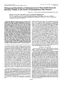
14. ABSTRACT
This report covers the period May 1, 1999- April 30, 2004 and contains a detailed description of the work conducted by the FY'99 MURI Consortium on Innovative Microwave Vacuum Electronics (MVE). The participating institutions were the University of California, Davis (Lead Instimtion); MIT; Stanford University; University of Maryland, College Park; University of Michigan, Ann Arbor; and the University of Wisconsin. The program was tightly focused on the critical need for a muUi-disciplinary basic research program focused on 21st Century MVE devices and the education and training essential to the contmuation of US preeminence. To ensure the accomplishment of the associated research and teaching goals, the Consortium developed a broad and well- integrated program involving close coordination with Industry and DoD laboratories. The strongly coordinated program drew on the institutions' strengths in microwave vacutmi electronics, plasma physics, antennas, computational science and engineering, materials science, and thermal engineering, thereby resulting in a muUiplicative factor significantly exceeding the sum of the individual programs. The participating institutions possess unparalleled facilities ranging from state-of-the-art measurement and diagnostic instrumentation to complete prototype manufacturmg capability as well as strong analytic theory and computational 15. SUBJECT TERMS
modeling capability.
16. SECURITY CLASSIFICATION OF: a. REPORT b. ABSTRACT c. THIS PAGE
17. LIMITATION OF ABSTRACT
UL
18. NUMBER 19a. NAME OF RESPONSIBLE PERSON OF PAGES 19b. TELEPHONE NUMBER (Include area code!
Standard Form 298 (Rev. 8/98)
BEST AVAILABLE COPY
Prescribed by ANSI Std. Z39.18
f- (o-oV
MURI'99 Innovative Microwave Vacuum Electronics Initiative Consortium
StaniDid flniuBrsitij
«n'«i««.a ^HUflifKA t>
UCDAVIS
UNIVBRSITY OF
Final Progress Report May 1, 1999-April 30, 2004 Dr. Robert Barker Program Manager Air Force Office of Scientific Research
Director Defense Research (&
Engineering
Investigators: J. Booske, G. Caryotakis, R. Gilgenbach, V. Granatstein, N.C. Luhmann, Jr., R. Temkin
TABLE OF CONTENTS TABLE OF CONTENTS 1.0 DIRECTORS OVERVIEW 7.7.7 Fast Wave Device Research 1.1.2 Slow Wave, Linear Beatn Device Research 1.1.3 Microfabricated Miniature Millimeter Wave and THz Sources and Systems 1.1.4 Crossed Field Device Research 1.1.5 Field Emitter and Carbon Nanotube Arrays 1.1.6 Thermionic Cathodes 1.1.7 Theory and Computational Modeling 1.1.8 MVED Materials Research 1.10 Education and Outreach 2.0 SIGNIFICANT ACHIEVEMENTS MAY 1,1999 - APRIL 30, 2004 2.1 UNIVERSITY OF CALIFORNIA, DAVIS 27.7 Wide Band High Gain W-Band Gyro-TWT 2.1.1.1 Need 2.1.1.2MURIActivity and Achievement 2.1.2 Compact, High Efficiency 40 to 160 GHz Sources 2.1.2.1 Need '. 2.1.2.1 MURI Activity and Achievement 2.2 STANFORD UNIVERSITY 2.2.7 Parallel Processing for Magic 3D Simulations 2.2.1.1 DoDNeed '. 2.2.1.2 MURI Achievement 2.2.2 Klystrino Circuit Microfabrication Improvements 2.2.2.1 Dod Need 2.2.2.2 MURI Achievement 2.2.3 Advances in Understanding ofRF Breakdown 2.2.3.1 Dod Need 2.2.3.2 MURI Achievement 2.3 UNIVERSITY OF WISCONSIN, MADISON 2.4 MASSACHUSETTS INSTITUTE OF TECHNOLOGY 2.5 UNIVERSITY OF MARYLAND, COLLEGE PARK 2.6 UNPVERSITY OF MICHIGAN, ANN ARBOR 3.0 QUAD CHARTS 3.1 UNIVERSITY OF CALIFORNIA, DAVIS 3.2 STANFORD UNIVERSITY 3.3 UNIVERSITY OF WISCONSIN, MADISON 3.4 MASSACHUSETTS INSTITUTE OF TECHNOLOGY 3.5 UNIVERSITY OF MARYLAND, COLLEGE PARK 3.6UNrvERSiTYOFMiCHiGAN, ANN ARBOR 4.0 PROGRESS 4.1 UNIVERSITY OF CALIFORNIA, DAVIS ^^.7.7 Fast Wave Device Research 4.1.1.1 UCD Heavily Loaded W-Band TEoi Gyro-TWT 4.1.1.2 34 GHz Second-Harmonic Peniotron 4.1.1.3 UCD Ka-Band Second-Harmonic Gyro-TWT Amphfier 4.1.2 Slow Wave Device Research 4.1.2.1 UCD Ka-Band TunneLadder TWT 4.1.2.2 3D Magic Modeling ofa Millimeter Wave EIK
1 1 7 3 4 5 5 6 6 7 8 9 9 ^ 9 9 77 11 12 12 72 12 12 14 14 14 16 16 16 17 18 18 19 21 22 23 24 25 26 27 28 28 29 29 35 41 46 46 49
4.1.2.3 Phase Noise Reduction in Radar TWTs 4.1.2.4UCD High Power Millimeter Wave Beam Steering/Shaping Antenna Arrays 4.1.3 Field Emitter and Carbon Nanotube Arrays 4.1.4 Graduate Students Supported by MURl 4.1.5 Publications Books/Chapters Journals Proceedings Conferences 4.2 STANFORD UNIVERSITY 4.2.1 MURI Program Accomplishments 4.2.1.1 Modular Millimeter Wave Klystron Research 4.2.1.2 Oxide Cathode Research Program 4.2.1.3 Plasma Deposition of Oxide Cathodes 4.2.1.4 Parallel Processing using 3D MAGIC on a Beowulf Cluster 4.2.1.5 RF Breakdown Experiments 4.2.2 Education and Training 4.2.3 Klystron Lecture Series 4.2.4 References 4.2.5 Publications 4.3 UNIVERSITY OF WISCONSIN, MADISON 4.3.1 Overview 4.3.2 Significant Achievements 4.3.2.1 Multi-sensored TWT for fundamental nonlinear physics research in MPM-class TWTs 4.3.2.2 The Physics of Nonlinear Distortions in Traveling Wave Tubes (TWTs) 4.3.2.3 Eulerian Modeling of Vacuum Electron Devices including charge overtaking 4.3.2.4 The Physics of Harmonic and Distortion Product Injection in TWT amplifiers 4.3.2.5 LFNC architecture for ultra-high efficiency linear transmitters of digitally modulated signals 4.3.2.6 The Physics of Impulse Amplification in wideband TWT amplifiers 4.3.2.7 Microfabricated TWTs for advanced millimeter-wave and THz regime sources 4.3.2.8 New Open Source Simulation Tools for TWT Research and Education 4.3.3 UW Students Educated under MURl'QQ 4.3.4 List of Publications and presentations 4.3.4.1 Journal Papers 4.3.4.2 M.S. and Ph.D. Theses and Reports 4.3.4.3 Conference Papers and Presentations 4.3.4.4 Publicity 4.4 MASSACHUSETTS INSTITUTE OF TECHNOLOGY 4.4.1 Summary of MIT Achievements 4.4.1.1 W- Band Gyrotron Amplifier Research 4.4.1,2.Photonic Bandgap Theoretical Research 4.4.1.3. Photonic Band Gap Gyrotron 4.4.1.4 Electron Beam Transport Studies 4.4.1.5 Novel Cathode Research 4.4.1.6 Theory of Crossed Field Amplifiers 4.4.2 National Student Conference Call Presentations 4.4.3 Students Educated Under MURr99: MIT. 4.4.3.1 MIT Graduate Students Supported by MURI 4.4.4 MIT Publications 4.5 UNIVERSITY OF MARYLAND, COLLEGE PARK 4.5.1 Executive Summary 4.5.2 Theojy and Modeling of Gyro-Devices 4.5.2.1 Analysis of multi-stage gyro-amplifiers (including frequency-multiplying devices) 4.5.3 Nonlinear and non-stationary phenomena in gyrotron oscillators 4.5.4 Computer Codes for Depressed Collectors in Gyro-devices (including tracing trajectories of backscattered electrons) 4.5.5 Design and Experimental Studies ofFrequency Multiplying Gyrotrons 4.5.5.1 Frequency-doubling Inverted Gyro-twystron using Multi-mode Resonant Circuits 4.5.5.2 Wideband Phase-locked Gyro-oscillator using Extended Interaction Output Cavity
51 57 70 76 78 78 78 79 84 89 90 90 92 94 96 97 100 101 101 101 104 104 105 105 106 107 108 109 110 111 112 113 115 115 116 117 123 124 125 125 125 125 126 126 127 127 128 128 128 131 132 133 133 135 136 136 139 139 143
4.5.5.3 Noise Measurements in a Frequency-doubling Gyro-TWT 4.5.5.4. Wideband Radial TEoi Mode Launcher for Gyro-TWTs 4.5.6 High Thermal Conductivity Materials with Tailored Losses (fabricated by microwave sintering) 4.5.7 Controlled Chaos In Microwave Tubes A.S.I.\ State-of-the-art 4.5.8 References 4.5.9 Publications 4.5.9.1 Books 4.5.9.2 Papers in Scientific Journals 4.5.9.3 Presentations at Conferences 4.6 UNIVERSITY OF MiciitGAN 4.6.1 Significant Achievements 4.6.1.1. 4A. Magnetron Noise Reduction-U. Michigan 4.6.1.2. 4B. Analytic theory of higher dimensional Child-Langmuir Law - U. Michigan 4.6.1.3. 4C. First theory of klystron intermodulation -U. Michigan 4.6.1.4. 4D. Heating of thin film on microwave windows 4.6.2. Progress 4.6.2.1. a) Magnetron Noise Reduction 4.6.2.1.1 5A. Magnetron Noise Reduction 4.6.2.1.2. 5B. Analytic theory of higher dimensional Child-Langmuir Law 4.6.2.1.3 5C. First theory of klystron intermodulation 4.6.2.1.4. 5D. Heating ofthin film on microwave windows 4.6.2.1.5 5E. Theory of Crossed-Field Electron Flow 4.6.2.1.6 5F. Injection Locking of Magnetrons 4.6.3 Students Educated Under MURr99 4.6.3.1 U. Michigan Graduate Students Working on MURI-Related Research 4.6.4 List of Publications and Presentations 4.7 MURI BOOK PROJECT Chapter 1. Introduction and Overview Chapter 2. Historical Highlights Chapter 3. Klystrons Chapter 4. Traveling Wave Tubes (TWTs) Chapter 5. Gyro-Amplifiers Chapter 6. Cros.sed-Field Devices Chapter 7. Microfabricated MVEDs Chapters. Advanced Electron Beam Sources Chapter 9. How to Achieve Linear Amplification Chapter 10. Computational Modeling Chapter 11. Next-Generation Microwave Structures and Circuits Chapter 12. Advanced Materials Technologies for MVEDs Chapter 13. High Power Microwave (HPM) Sources Chapter 14. Affordable Manufacturing Chapter 15. Emerging Applications and Future Possibilities 5.0 PUBLICATIONS
146 151 153 157 158 158 162 162 162 164 167 167 167 167 167 168 168 168 168 168 169 169 170 170 171 171 171 174 177 177 179 180 180 181 182 183 184 185 186 188 188 189 189 191
1.0 DIRECTORS OVERVIEW This report covers the period May 1, 1999- April 30, 2004 and contains a detailed description of the work conducted by the MURI Consortium on Innovative Microwave Vacuum Electronics. The participating institutions were the University of California, Davis (Lead Institution); MIT; Stanford University; University of Maryland, College Park; University of Michigan, Ann Arbor; and the University of Wisconsin. The program was tightly focused on the MURr99 Topic #11 description which succinctly identified the critical need for a multi-disciplinary basic research program focused on 21st Century MVE devices and the education and training essential to the continuation of US preeminence. To ensure the accomplishment of the associated research and teaching goals, the Consortium developed a broad and well- integrated program involving close coordination with Industry and DoD laboratories. The strongly coordinated program drew on the institutions' strengths in microwave vacuum and solid state electronics, plasma physics, antennas, computational science and engineering, materials science, and thermal engineering, thereby resulting in a multiplicative factor significantly exceeding that of the sum of the individual programs. The participating institutions possess unparalleled facilities ranging from state-of-the-art measurement and diagnostic instrumentation to complete prototype manufacturing capability as well as strong analytic theory and computational modeling capability. As described in more detail in the body of the Report, this has been an extremely productive endeavor. In the following, highlights from the past five years are briefly enumerated. /././ Fast Wave Device Research Fast wave device research was conducted at UC Davis, MIT, and the University of Maryland. The aim of these activities was to provide a fixndamental understanding of device physics and to develop new concepts to satisfy DoD needs for coherent amplifiers for applications such as imaging radar as well compact, oscillators for nonlethal defense applications. Five innovative gyro-devices were investigated in the MURI-MVE program at UC Davis and which were designed for operation in W-Band and Ka-Band, the most important bands for future DoD millimeter-wave applications. A major emphasis these experimental activities has been aimed at a (potentially) high average power W-Band gyro-TWT operating in the low-loss TEg, mode, which significantly improves upon the characteristics of the recent NRL-industry high average power W-Band TEoi gyro-klystron amplifier with the focus being the need for wide bandwidth sources for imaging radar. The UCD gyro-TWT is driven by a 100 kV, 5 A, v^/vz=1.0 MIG electron beam with Av2;/vz=2.2% reduce this to 2.2% with attendant increases in gain and bandwidth. The single-stage amplifier has been fabricated and is predicted by a largesignal simulation code to generate 140 kW at 94 GHz with 28% efficiency, 50 dB saturated gain and 5% bandwidth. Hot testing of the gyro-TWT continues with 61.2 kW saturated output power, 40 dB gain, 17.9 % efficiency, and 1.5 GHz (1.6%)) bandwidth under zero drive stable conditions obtained for an 87 kV, 3.9 A beam and a magnetic field of 35.1 kG. Significant improvements are expected (both in bandwidth and power) when the testing of the seventh version is completed in July. A dual mode gyro-BWO has been designed to yield high power over a broad bandwidth for fiiture ECM applications. The two tuning modes of the gyro-BWO are fast tuning by changing
the cathode voltage and slow tuning by changing the magnetic field. If will utilize much of the TEoi gyro-TWT circuit. The TEoi gyro-BWO has been modeled with a self-consistent particletracing simulation code. The tapered device has been fabricated and is predicted to generate 100 kW near 94 GHz with over 10% tuning capability. Testing will commence following the completion of the gyro-TWT tests. The UC Davis second-harmonic peniotron experiment is designed to demonstrate high device efficiency (-47%) and power output (-125 kW) at 34 GHz. It is intended as a first step towards higher frequency devices and an amplifier based on the peniotron interaction with the goal being stable operation at 94 GHz. The device incorporates a four-vane slotted circuit which supports the interaction of the fundamental cavity mode with the second-harmonic of the 70 kV, 3.5 ampere, axis-encircling electron beam. The circuit has been delivered and verified on cold test. The cusp electron gun is supplied by Northrop Grumman. Recent effort has concentrated on the re-design of the magnetic field to ensure high beam quality and safe operation. The magnetic assembly is complete and has been verified by measurement. Simulation of the beam, incorporating the new magnetic field profile, predicts greatly improved beam quality. Continuing efforts are focused on effort completing design of the collector, finishing assembly and verifying performance of the device. An Invited Talk on this work was presented by Ph. D student Larry Dressman at the Int. Conf on Infrared and Millimeter Waves held in Toulouse, France. A high-harmonic W-Band slotted gyrotron was designed and constructed at UCD in collaboration with the Air Force Phillips Laboratory that will be driven by a 70 kV, 3.5 A, axisencircling electron beam from a Northrop Grumman Cusp gun provided under a DURIP grant. The 94 GHz, slotted sixth-harmonic gyrotron has been fabricated and is predicted to generate 40 kW with a device efficiency of 16%. Resumed testing awaits the completion of the W-Band gyro-TWT and BWO studies. A second-harmonic Ka-Band TE21 gyro-TWT amplifier with an axis-encircling electron beam is being developed that is intended to address the need for high power broadband compact lightweight sources for DOD radar and communications applications. The device utilizes hamionic operation to reduce magnetic field requirements and to obtain higher power and greater stability. The gyro-TWT incorporates a Cusp gun developed by Northrop Grumman under DURIP/MURI funding which provides a 70 kV, 3.5 A axis-encircling electron beam. The device is predicted to nearly double the efficiency of the previous UC Davis 200 kW, 12% efficient, MIG second-harmonic Ku-Band gyro-TWT since the new device will avoid the loss in efficiency due to off-axis electrons interacting with a linearly polarized mode. The secondhamionic TE21 gyro-TWT amplifier has been designed, simulated and built and is being assembled for test and is predicted by our large signal code to produce 50 kW in Ka-band with 20% efficiency, 30 dB saturated gain and 3%) bandwidth. At the University of Maryland, interest has centered on the nonlinear behavior of vacuum electronic devices. They have been studying both theoretically and experimentally a harmonic doubling gyro-TWT with a clustered cavity bunching section. An output power of 40 kW was realized with 13%) efficiency in Ka band; the amplifier frequency range was 1 GHz. Such an amplifier is inherently nonlinear and is directly applicable only in systems employing amplifiers working in saturation (e.g., high power radar); however, where applicable it has been shown to have certain practical advantages. They have also developed a theory which explains recently observed nonstationary behavior in gyro-BWOs and have carried out a theoretical study (with separate but related NRL support) of chaos in a conventional TWT with feedback. Nonstationary
and chaotic behavior in gyro-BWOs and TWTs and gyro-TWTs is recommended for future study. There is direct relevance to such DOD interests as jam resistant radar and secure communications. A major event in the MIT MURI program was the successful operation of a novel 140 GHz quasioptical gyrotron traveling wave tube (gyro-TWT) amplifier at a record high power level, namely 30 kW, a significant advancement in the state-of-the-art in gyrotron amplifiers. The gyro-TWT produced up to 30 kW of peak power in 2 |is pulsed operation at 6 Hz achieving a peak gain of 29 dB, a peak efficiency of 12 % and a bandwidth of 2.3 GHz. 1.1.2 Slow Wave, Linear Beam Device Research TWTs are nearly ubiquitous in DoD systems finding application in communications, radar, and ECM. This has motivated research activities at both the University of Wisconsin and UC Davis. TWT phase noise reduction techniques have been investigated by UC Davis MURI Ph.D student Jae Seung Lee in cooperation with Teledyne Microwave Electronic Components. Phase modulation based communications, such as multi-PSK, Doppler radar and MTI (Moving Target Indicator) radar all requires extremely low phase noise TWTAs. One of the approaches which yielded excellent results utilizes an envelope feedback loop, which has the advantage of correcting the slow phase variation. This method resembles the conventional phase-locked loop (PLL) in which the detected output phase noise is compensated through a voltage controlled phase shifter The importance of the TWT is reflected in the strong emphasis in the University of Wisconsin program. There, the activities are broad and comprehensive and include: •
Developing and operating a novel, multi-sensored TWT for research of fundamental nonlinear physics in MPM-class TWTs,
•
Advancing a new understanding of the physics of nonlinear distortions in TWTs,
•
Developing a new computational method to model 1-D linear-beam VEDs with Eulerian formulations, including the effects of charge overtaking,
•
Establishing the fundamental physical mechanisms of hamionic and distortion product injection for linearization of TWTs,
•
Identifying a novel TWT transmitter configuration enabling extremely linear amplification of digitally-modulated signals while operating saturated and thus at maximum efficiency,
•
Completing the first combined experimental and simulation study of impulse amplification in TWTs revealing realistic prospects for novel applications to impulse radar, impulse communications, and impulse response measurements of small signal gain characteristics,
•
Conducting investigations of X-ray LIGA, UV LIGA and deep reactive ion etching methods for microfabricating millimeter wave and THz regime TWTs, and
•
Developed and disseminated a suite of 1-D TWT simulation codes for teaching and research of TWTs, making them available as open source software at http://www.lmsuite.org.
1.1.3 Microfabricated Miniature Millimeter Wave and THz Sources and Systems A significant emphasis area of the MURI99 Innovative Vacuum Electronics program has been in the use of advanced microfabrication techniques to develop miniature millimeter wave and THz sources. This makes use of a variety of approaches including LIGA, SU-8, and advanced milling/etching techniques. A wide variety of complimentary activities have taken place at Stanford, UC Davis, and the University of Wisconsin. Unquestionably, the leader in the microfabricated MVED field has been Stanford who have not only successfully fabricated and cold tested structures, but who have also propagated beams through them. A major thrust of the Stanford research has been directed toward the development of a 100 kW peak power, 1 kW average power,W-band klystrino. The goal of the research is to produce significant average power at W- band (95 GHz) in a compact lightweight package which has application in both radar and nonlethal defense systems. While researching alternative fabrication methods for the klystrino project, two alternate methods of lithographic circuit manufacturing were investigated by the Stanford team. The original klystrino circuit required dozens of post-LIGA machining steps because it used a roughened aluminum substrate for a base material and because the gold lithographic mask was bonded to the top of the PMMA photoresist. Attempts at using a smooth copper substrate failed because of poor adhesion of the PMMA and undercutting due to x-ray scattering from the copper base. Substituting SU-8 epoxy as the photoresist provides multiple benefits. First, the SU-8 is 200 times more sensitive to x-rays than PMMA. This means that the exposure times can be cut by two orders of magnitude and the effects of backscattering are negligible. Second, SU-8 is also sensitive to UV exposure which means that the LIGA process can be divorced from the synchrotron light sources that were its major shortcoming. Two 1 mm tall test circuits were made using SU-8. One was fabricated at SRRC with their x-ray source, the second was done at a small business using a commercial UV source. Both produced good results with specular surface finish. Other Stanford activities have included the design of a microfabricated W-Band sheet-beam klystron. In addition, a collaboration involving UCD, Stanford, and Seoul National University is pursuing the development of LIGA fabricated TWTs. Yet another endeavor involves a collaboration which has the goal of making a dramatic advance beyond the MPM wherein an entire microfabricated TWT based millimeter wave transmitter is fabricated on a single substrate. The University of Wisconsin group has specifically focused on the folded waveguide (FWG) TWT as one whose circuit is naturally suited to planar microfabrication methods. To date, they have successftilly demonstrated the feasibility of fabricating 400 GHz FWG TWT circuits using conventional X-ray LIGA, novel UV LIGA, and deep reactive ion etching (DRIE). A significant UCD emphasis area is in the use of advanced microfabrication techniques to develop miniature millimeter wave and THz sources. This makes use of both LIGA and advanced milling/etching techniques. The collaborative activities with Stanford aimed at the development of LIGA fabricated W-band klystrinos is described below under their portion of the overview. In parallel, a collaboration aimed at involving UCD, Stanford, and Seoul National University is pursuing the development of LIGA fabricated TWTs. Yet another endeavor involves collaboration with Profs. R.J. Hwu and L. Sadwick, which has the goal of making a
dramatic advance beyond the MPM wherein an entire microfabricated TWT biased millimeter wave transmitter is fabricated on a single substrate. A major disadvantage of MPM/MMPM based phased arrays is that despite their small size, it is physically impossible to place them sufficiently close {d "^ CO 75
4000 ■
0.
^ ^^
30 -•IT-*
.^
f
i
180
S
160
-
140 I 1
120
iP"^
100 16
18
20
22 24 26 Frequency (GHz)
28
30
20
32
22
24
26
28
30
32
Frequency (GHz)
Fig. 4.1.27. Dispersion results (left figure) and the impedance simulation/calculation (right figure) which shows the maximum gain would be around resonance 30 GHz.
48
•
"' 11
T _«—1—»_j—«1»ii ■••^—
20
22
24
26
28
30
Frequency (GHz)
Fig. 4.1.28 Attenuation results were obtained where the conductivity of the wall, ridge and ladder were assumed to be S/m. In addition, the dielectric constant of the dielectric support was set equal to 5.5 and no loss tangent was input. The couplers and transitions have been added and modeled by MAGIC 3D. The results are currently under examination.
Input port "^— Inductive iris
Capacitivo post —- "
Output port— •
Fig. 4.1.29 Simulation of TunneLadder Traveling-Wave Tube Input/Output Coupler Characteristics Using MAFIA, C. L. Kory, NASA Contractor Report 198505, Sep, 1996 4.1.2.2 3D Magic Modeling of a Millimeter Wave EIK MURI student Hsin-Lu Hsu has also been working under the direction of Glenn Scheitrum and George Caryotakis to carry out a full 3D Magic modeling of a millimeter wave EIK. The motivation for investigating the elliptic extended interaction klystron is to widen the bandwidth beyond that available from conventional klystrons. The device under study is aimed at
49
relatively high power output which is facilitated by the use of a coupled cavity configuration. The required tuning of the individual cavity resonant frequencies is greatly simplified by the use of an elliptic shape. As can be seen from an examination of Fig. 29, the flat, deformable surface permits easy tuning and easy fabrication using a standard end mill.
Beam Adjustable / Surfaces
Fig. 4.1.30. Single elliptic cavity By using the standard one dimensional small signal and large signal codes, an initial design achieves IkW at 35 GHz and 200 MHz bandwidth. However, three dimensional modeling is obviously necessary since the geometry is not symmetrical with respect to any of the axes. By using Magic 3D, a complete tube structure has been built which requires an enormous amount of computer memory (see Fig. 30 below). By dividing it to individual cavities, it was possible for the initial modeling to run on single CPU, albeit extremely slowly with a typical run taking about one week. A parallel Linnux in SLAC will be used to handle the hot test simulation for a complete modeling of the EIK. The status of the modeling activity was given by Ms. Hsu in an Invited talk: "Computer modeling of elliptic EIK using Magic 3D", MAGIC User Group meeting, April, 27, 2004, Monterey.
50
RF Output
\\
^
Coupling ' Iris
-2"%' '^^
* -^
Coupled Cavity RF Input
\
•
, -
Fig. 4.1.31. Complete 3D modeling \\
V *
of EIK using MAGIC 3D.
4.1.2.3 Phase Noise Reduction in Radar TWTs TWT phase noise reduction techniques have investigated by MURI Ph.D student Jae Seung Lee in cooperation with Teledyne Microwave Electronic Components. Phase modulation based communications, such as multi-PSK, Doppler radar and MTI (Moving Target Indicator) radar all require extremely low phase noise TWTAs. One of the approaches which has yielded excellent results utilizes an envelope feedback loop, which has the advantage of correcting the slow phase variation. This method resembles the conventional phase-locked loop (PLL) in which the detected output phase noise is compensated through a voltage controlled phase shifter Although solid state amplifiers typically have smaller volume, lower noise figure and easier implementation capability compared with tube based RF amplifiers, the limited output power available in the higher frequency ranges has resulted in the continued dominance oft vacuum power amplifiers for many applications, especially low to medium PRF (Pulse Repetition Frequency) pulse radars. The larger metallic structure and collector of tube amplifiers allow higher terminal power handling and higher efficiency, respectively. The specific amplifier studied by Mr. Lee is part of a radar transmitter and is an MTG-5336 triband (C, X, Ku band) communication TWT provided by Teledyne Microwave Electronic Component Inc. The typical operation conditions are: cathode voltage and current for continuous wave output 10.94 kV and 340 mA, respectively. The output power is 58 dBm and the power gain is around 42 dB over Xband. Radar receivers respond not only to the desire target signal, but also to strongly reflected cutter. Figure 31 illustrates two targets with different speeds and different cross sections. The solid line over the offset frequency band is redrawn clutter which hides desired low level target reflections. This research work proposes and proves that a phase locking feedback can increase probability of detection reducing inherent phase noise of TWT by the dotted line in the figure.
51
Clutter Reflection
Offset Frequency Target (A): Not detectable Target (B): Detectable, but must be sufficiently fast Fig. 4.1.32. Radar target reception Radar, in general, is operated in the deeply saturated regime where phase noise becomes an extremely important factor. The phase noise can be determined on the basis of a basic FM (frequency modulation) theory. If a signal of interest is phase modulated, one can express its phase noise as follow; Phase modulated signal; V(t)=V cos(2fi©)'' +A ^ t Phase noise spectral density; T(f\- ^v^^^
A^(0
^^-*^1^^
The phase variation term, can be a random noise signal. The single side band spectral density expression of phase noise is expressed in standardized terminology in units of dBc/Hz. Figure 32 shows the dissertation goal of the TWT phase noise reduction. The green line indicates lESS (Intelsat Earth Station Standards) and specifies the phase noise spectral density from 10 Hz to 1 MHz of offset frequency for oscillators, amplifiers, and up-down converters used in satellite communication. It is of interest to note that the inherent TWT phase noise, plotted as the black dotted line, is about 40dB below the lESS specification. The aim of Mr. Lee's work is to obtain an additional 20dB of improvement, which will significantly improve the overall efficiency of radar transmitter, reduce transmitter size (via the relaxation in power supply filtering requirements) and allow multi-channel use in radar.
52
N
X
m
■D in
c Q ■(5
« a. en 0) tn
in
1000
10
Offset Frequency (Hz) Fig 4.1.33. Phase noise spectral density versus offset frequency illustrating the research goals. The major phase noise source is the unstable dc voltage of the HVPS (High Voltage Power Supply). The jitter on top of the cathode voltage causes beam velocity modulation which is, in turn, converted into phase jittering. One can simply derive the relation between the voltage fluctuation on HVPS and the followed phase change,, with the aid of electron motion theory. Ignoring nonlinear effects, the electrons are assumed to ^,^^ move in the influence of a static electric field. The velocity of the electron and the phase of RF signal are: /2eV _, ^,, 27if, v=J and, 0(t)= L V m v For V=VDc+Vrippie, the phase change becomes: 2m
0(t)=nfL
e(VDC+Vripp|e)
The common method to reduce this voltage fluctuation is to employ a regulator together with large capacitive filtering. This conventional method is rather simple and effective, but results in large space requirements and increased weight. In addition, additional factors arise in the case of pulsed mode operation. Since the Fourier frequency response of a rectangular pulse extends from dc to infinity, frequency domain filtering loses effectiveness. Consequently, Mr. Lee's research has focused on real-time detection of phase jitter and compensation by the required amount. As shown in Fig 33, a double balanced mixer discriminates the phase difference between the "clean" 53
input signal and the phase noise added output signal of the TWT amplifier. With 16 V/degree of conversion, the converted video voltage signal is readily able to drive a voltage controlled phase shifter prior to TWT input. This video signal experiences two conversions; phase to voltage and voltage to phase in mixer and voltage controlled phase shifter, respectively. Therefore, the video amplifier is designed to compensate for this total conversion loss. In the mean time, nonlinear effect of the mixer creates dc bias and harmonics so that dc blocking and a low pass filter are also required in the transition. The manual phase shifter in the left hand side of system adjusts the fine difference of time delay between the two paths towards the mixer. Phase noise measurement is performed with an HP L1500A spectrum analyzer and E5500 software. The first result demonstrates phase noise reduction in CW (Continuous Wave) mode operation. As shown in Fig 34, 20-25 dB of improvement was achieved.
Phase Shifter (Phase Compensation)
0 Phase Shifter
Mixer
Fig 4.1.34. Phase locking feedback loop method system schematic
54
-20
N
I o m
■ lESS Phase Noise Standard forTWTA ■Phase Noise (Withoutcompensation) ■ Phase Noise {With compensation) - Anaren Mixer
at
c
0) Q
cn
a.
Offeet Frequency (Hz) Fig 4.1.35. Phase noise reduction for CW operation, carrier frequency is 8 GHz In pulsed radar, PRF is an important parameter as long as both Doppler and range ambiguities are concerned. To verify phase noise reduction for high PRF operation, two case studies were performed; 20% duty cycle with 50)is pulse width, and 5% duty cycle with 25jxs pulse width. For both cases, the tuned system is maintained in the same state for the entire frequency sweeping measurement. The carrier frequency was swept from 7.7 to 8.3 GHz, because 500MHz of bandwidth is the maximum required in general radar operation. In Fig 35 and Fig 36 are measured results in the 20% duty case. Figure 35 shows the inherent phase noise spectral density in the green line and the reduced noise in red for 8.0GHz carrier operation. Five sets of reference noise and reduced noise spectra were measured, respectively. The amount of reduction versus offset frequency is plotted in Fig 36. Over 500MHz of bandwidth, about 20 dB of consistent improvement was achieved. Similarly, results for the 5% duty case are also presented in Fig 37 and 38. These preliminary results were presented by Mr. Lee at both the 5th IEEE International Vacuum Electronics Conference, Monterey, California, USA, April 2004 and the IEEE International Microwave Symposium, Fort Worth, Texas, USA, June 2004.
55
Pulsed Mode Phase Noise Reduction (dB) 20% Duty Cycle (50us pulse width)
50
7.7 GHz (Phase Noise Reduction) 7.8 GHz (Phase Noise Reducliai) 8.0 GHziPha.'je Noiss Raductiori) 8.2 GHz (Phase Noise Reduction)
Pulsed Mode Phase Noise Spectral Density (dBc/Hz) 20% Duty Cycle (SOUS pulse width)
40
30
'
A
\
1
/
01
«
====^ ^
o 20 z
//
10
100
X!
10
1000
....
'■+"■"
1000
100 Offiset Frequency (Hz)
Offset Frequency (Hz)
Fig. 4.1.36 Phase noise measured for pulsed mode Fig. 4.1.37 Phase noise reduction for pulsed operation with 20% duty cycle (50 |is pulse), mode with 20% duty cycle (50 |^s pulse) carrier frequency is 8GHz carrier frequency from 7.7-8.4 GHz Pulsed Mode Phase Noise Spectral Density (dBc/Hz) 5% Duty Cycle (25us pulse width)
1
1
30 ■100
25
,£• « -120 a
«-140
^'^'^-s. 1
wu-j
u
W^\Ayvl 1^
1
\
id
fmHh1pM )f\ \\
\
■160
Pulsed Mode Phase Noise Spectral Density (dSc/Hz) 5% Duty Cycle (25us pulse width)
^^ \
^-^ p-^^^^r;15
—1-
7.7 GHz (Phase Noise Reduction) 7.8 GHz (Phase Noise Reduction) S-0 GHitPha^'e Noise Retluction)
• 10
-^
"_
-^^^ V
\ -180 10
100
1000
100
1000
Offset Frequency (Hz)
Offeet Frequency (Hz)
Fig. 4.1.38 Phase noise measured for pulsed mode Fig. 4.1.39 Phase noise reduction for pulsed operation with 5% duty cycle (25 \is pulse), mode with 5% duty cycle (25 us pulse) carrier frequency is 8GHz carrier frequency from 7.7-8.3 GHz
56
4,1.2.4 UCD High Power Millimeter Wave Beam Steering/Shaping Antenna Arrays MURI students Chia-Chan Chang and Yaping Liang have been focused on the development of novel millimeter wave beam steering/shaping phased antenna arrays (PAAs) at Ka-band and Wband which are intended to be used with millimeter wave vacuum electron beam sources. The major problem with conventional millimeter wave tubes is that their size poses a serious impediment since this prevents them from being spaced less the requisite maximum X/2 value. Investigations at NRL have concluded that even such measures as removing the covers from TWTs restrict conventional approaches to a maximum frequency of approximately. This has led them, as well as researchers in the MURI Vacuum Electronics Program, to investigate novel approaches involving microfabricated arrays (see Sec. 4). The conventional approach to high frequency PAAs is to utilize solid-state T/R modules since they offer the possibility of greatly reduced element spacing. However, they suffer from a number of serious limitations such as cost and power, particularly at high frequencies. In fact, even the highest frequency devices (i.e., InP HEMTs) are restricted to considerably lower operating frequencies than VEDs in addition to offering much lower output powers. The approach taken by Ms. Chang, in contrast, employs high power VED sources followed by compact and efficient power splitters and delay lines which can handle high powers and which feed antenna radiators spaced less than X/2 apart. This approach satisfies the growing need for radar and communication systems both in military defense and commercial applications which employ phased array based beam steerers and beam shapers. Two phased antenna arrays are currently under development in these initial basic studies. The operation frequency for the first system is set as 18 GHz for initial testing. The second PAA system is designed to operate in the Ka-band range (38 GHz). Furthermore, a W-band PAA is also currently under design and is intended to operate at power levels appropriate for current DoD applications including Active Denial systems. A major function of a PAA is to scan the main beam into the desired direction as well as to provide beam-shaping capability by appropriate arrangement of the feed signals. This is accomplished by appropriately changing the relative phases of the antenna elements or by programming time delays between elements. In this MURI research, considerable attention is given to a system employing the true time delay approach developed by K. Chang [1] which utilizes a piezoelectric translator (PET)-driven perturber to vary the propagation velocity along low loss transmission lines. A programmable DC bias causes the PET to move the dielectric layer, thereby perturbing the electromagnetic field of the transmission line. The variation in effective dielectric constant results in the change of propagation constant, A/3, and consequently results in a time delay type phase shift A^.
A/5=^.T^;^-Vv(7))
'I. Here, Sef/f) is the frequency dependent effective dielectric constant under maximum perturbation, while s'ejf(f) is the value under the minimum perturbation, while Lp is the length of dielectric perturber. The piezoelectric material, which is comprised of Lead Zirconate Titanate ceramic, was purchased from Piezo System, Inc. The maximum free deflection is about + 1300 |j.m when applying ± 90 volts. Figure 39 shows the photograph of microstrip line-based PET phase shifter and Fig. 40 shows the measured phase shifts for different frequencies and different air gaps. 57
Dielectric Perturber
+5avoit
Fig. 4.1.40
True-time delay type, microstrip line-based PET phase shifter
PET perturbers based on different transmission media have been investigated. For the case of a transmission line with the ground on the same surface with the signal line (eg. coplanar waveguide, coplanar stripline and slot line), the density of the electric and magnetic field lines in the air is greater than in the microstrip lines. Therefore, the perturbation effect is more significant. Figure 41 shows the comparison of different transmission media. The simulation results indicate that both coplanar waveguide and coplanar stripline can generate greater phase shift as compared to microstrip line. In this beam steering/shaping antenna array design, coplanar stripline (CPS) has been chosen. In addition to the attractive perturbation characteristics, the balanced structure of CPS also facilitates connection to the transmitting antennas without introducing additional baluns.
58
'
' ' ' ' -10 g" -20
•a
-'■'■'■"'-"■"•'
' .^U.'^i,i.Lrfa
.
/ /
■
2 GHz (phase shift)
-30
/^
>*'■■
0
-40
■
/
»
"X 9
i
/ /
9
/
-^ ■■ /
J
5 GHz (phase shift) - 15 GHz (phase shift -->■--10 GHz (phase shift; —3— 20 GHz (phase shift
-50
, , , ,
-60 10
1
20
1
1
1
i
30
1
1
1
1
40
50
DC Bias (volt)
Fig. 4.1.41. Measurement results for microstrip line based PET phase shifter. The microstrip line was designed as 55i2 (21 mil) at 20 GHz and fabricated on 25-mil, RT/Duriod 6010.2 (Sr =10.2). Theperturber used the same material and was 0.8" long and 50 mil thick.
59
0.05
0.1
0.2
0.3
0.4
0.5
0.6
0.8
Air Gap
Fig. 4.1.42 Simulation comparison of the phase shift caused by PET perturber based on different transmission media
For the proof-of-principle studies, an 18 GHz PAA has been designed and fabricated on 20-mil GMLIOOO substrate (sr =3.05). The entire system layout is shown in Fig. 42. The microwave signal is first fed via an 8-way microstrip-based power divider, and then passes through the microstrip to CPS transition. The CPS-based, PET perturber, which is controlled by the DC bias, provides the true time delay. Finally, the resultant RF signal is then fed directly to a planar tapered slot antenna with half wavelength spacing between each channel. The overall system size is about 5" x 8". Figure 43 shows a photograph of the fabricated circuit.
60
CPS-to-microstrip transition
Copianar stripline (CPS)based PET piiase shifter
Fig 4.1.43 Circuit layout of 18 GHz beam steering/shaping phased antenna array
61
Fig. 4.1.44. Photograph of 18 GHz, beam steering/shaping antenna array (5"x8")
For the 38 GHz PAA system, the entire structure will be similar to the 18 GHz system, except that the substrate material has been replaced by 10-mil RO3203 (sr =3.02). To achieve lOOW output power, the major consideration of the entire system design is the power handling capability. The power-handling capability of a transmission line is limited by dielectric voltage breakdown and by excessive heating due to attenuation. The electrical breakdown limits the peak power, which is mainly considered under pulsed operation. Under continuous wave (CW) operation condition, the increase in temperature due to conductor and dielectric losses limits the average power. When the operating temperature is too high over prolonged periods of time, the concern is that the traces will loose adhesion to the base dielectric and eventually delaminate. Therefore, it is crucial to ensure that the operating temperature is maintained below the rated value for the given material. For this Ka-band, lOOW output PAA design, the entire system will remain the same as the previous 18 GHz PAA design except for the CPS-based PET perturber and feeding method. In the previous 18 GHz PAA design, the CPS structure was chosen in the PET perturber region instead of microstrip line to generate more time delay. However, according to previous studies, microstrip line has the highest power handling capability comparing to other transmission media in this general category. Hence, microstrip line should be chosen over CPW and CPS here to accommodate the high output power requirement.
62
The maximum average power (Pave) under CW conditions was addressed in detail by Gupta [2] and is given by
where ^is the temperature rise above ambient (°C), In general, maintaining the continuous operating temperature below 125°C is recommended which means that 0 should be less than 100°C (assuming 25°C ambient temperature). Here, AT is defined as the temperature rise to indicate the density of heat flow caused by power absorption per unit length
In the above, h is the substrate thickness, K is the thermal conductivity of the substrate, oc and UD are the conductor and dielectric losses, and Wefmd Wej}(f) are the effective microstrip widths. As expected, the substrate material dominates the temperature rise as well as the maximum average power for CW power transmission conditions. Therefore, it is obviously advantageous to select a material with higher thermal conductivity K when it comes to power handling. Additionally, the thinner substrate and larger microstrip geometries will result in improvements in power handling. In this 38 GHz PAA system, the substrate was chosen as 10-mil RO3203 (sr =3.02, K= 0.47 W/m-K; Rogers Corp.). The 50Q transmission line design will result in a temperature rise AT given by 5.2837 °C/W [3]. In other words, 18.93 W incident RF power will cause a 100°C temperature increase. If the system is still fed by a coaxial connector through a l-to-8 power divider, approxiamatelylSO W input power is required to overcome all losses and to provide the required output power level. Consequently, there will be overheating at the input port. Therefore, we need to employ a different RF signal feed configuration. The proposed method is to use a custom designed oversized waveguide with a gradual transition from the standard WR28, Ka-band waveguide. The individual receiving antenna elements, which are spaced half a wavelength apart, will replace the coaxial connector and power divider. The entire PAA will be driven by a Ka-band high power tube. The system schematic is shown in Fig. 44.
63
Microstrip-based PET perturber Waveguide gradual transition to oversize openin Connect with output port of high power tube
Transmitting antenna array Receiving antenna array WR-28, Ka-band waveguide
Fig. 4.1.45. Schematic of proposed Ka-band, 100 W output power, phased antenna arrav
A standard WR-28 waveguide can usually drive 22-31 kW power, and therefore should be able to readily handle the high power level coming from the tube. The possible power losses through the entire system could come from the waveguide transition, antenna radiation loss, microstrip line loss, and/or possible mode conversion problems due to the multi-mode operation. Accounting for all possible losses, at least 12 channels are required to ensure 100 W output power. The overall size has been predicted as 2.5" x 4". For the W-band PAA system, it seems prudent to utilize a high dielectric constant substrate and a slow wave propagation velocity; this reduces the radiation loss from the circuits. However, at the higher frequencies of future interest to the DoD, the circuits get impossibly small, which restricts the power handling capability as well as increases the fabrication difficulties. Additionally, the piezoelectric controlled phase shifter will not be suitable for use at such a high frequency range due to its large size. Microelectromechanical systems (MEMS) switch based delay hence is a good candidate to generate the required time delay. 10-mil fused quartz (Sr=3.8, K=1.4 W/m-K) has been chosen as the substrate material in this W-band PAA design based on its compatibility with standard microfabrication techniques. Calculation shows that 50Q transmission line designs (assuming a center frequency of 88 GHz) will result in a temperature rise zirof 2.2739 °C/W, which means that a maximum of 43.98 W RF power is allowed to flow through each channel before reaches 100°C temperature increases. Here we note that the recent availability of large, high quality CVD diamond substrates makes this attractive for even higher power operation. CVD diamond exhibits remarkable dielectric properties including a low dielectric constant of 5.7, a loss tangent below 0.00005 at 145GHz and a high thermal conductivity of 2000-2500 W/m-K. This thermal conductivity value has been found as the highest of any material at room temperature. Assuming that 10-mil CVD diamond is chosen as substrate material for W-band PAA design, the 50Q transmission line at 88 GHz designs will result in a temperature rise AT of 2600 °C/W, which makes a single channel be able to handle maximum 37780 watt before reaches 100°C temperature increases, almost 85 times larger than fused quartz. 64
Similar to the previous cases, an endfire tapered slot antenna is still chosen here because it has many advantages including wide bandwidth, high gain and narrow beam width. Other researchers have shown that the effective substrate thickness normalized to the free-space wavelength must satisfy the following relationship to exhibit traveling-wave characteristics [4]: At high frequencies, this results in a fragile structure. To improve the mechanical stability,
^.^/^o=[(V^-l)-^Mo]^0.03 micro-machining holes can be employed to remove a portion of the underlying substrate, thereby reducing the effective thickness and effective dielectric constant but still maintaining good mechanical properties. This method was first presented by researchers at the Radiation Lab. at the University of Michigan, and successfully demonstrated at 94 GHz [5]. Figure 45 shows the Agilent HFSS simulation model for this micro-machining substrate. The related effective dielectric constant can be calculated by the following equation:
'eff
n ,D. 2 W
— ■ (—) + s^ ■
'
2
W
Fig. 4.1.46. HFSS simulation model for W-band single slot antenna with the micro-machining substrate The simulation results shown in Fig. 46 reveal that the 10-mil thick substrate (green curve) generated the undesired patterns; reducing the substrate thickness to 4.24 mils will efficiently improve the antenna patterns (blue curve). Using the 10-mil thick substrate, but removing a portion of the underlying substrate, will also generate good patterns (orange curve).
65
The need for MEMS switches for microwave and millimeter applications has dramatically arisen in the past decades based on their numerous advantages including low cost fabrication, extremely high ON/OFF contrast ratios, low insertion loss, high isolation and relatively high power handling capability. The MEMS switch can be configured to generate phase shift by switching between two different signal paths (digital-type), or can be used as a distributed capacitive switch to change the effective capacitance of the transmission line (analog-type). Figure 47 shows the digital-type MEMS switched delay line. The phase shift is determined by the difference between the two path lengths, which is selectively controlled by DC bias.
I
-40 -90
-60
.. I
I
I
I
-30
.....
I
I
...
0 Degree
I
30
.....
I
60
..'' I
90
Fig. 4.1.47. HFSS W-band single antenna pattern simulation results for three different cases (a) 10-mil quartz substrate (b) 10-mil quartz substrate with micromachining holes (Resulted in eeff=1.969) (c) Corresponding substrate thickness = 4.24mil, which satisfies:
66
MEMS Switch
Bias Pad
■■ / 1 ■■
IS RF Input
E ^■■■ ' i
yn
■^
High Impedance Bias Line
r ^
_j;_
i_
Bias Pad
■i fT'- "'-^1
¥ i™-i
RF Output
„-,„,.,,—„„,!;
1 96 ps Delay
48 ps Delay
^ 24 ps Delay
12 ps Delay
6 ps Delay
3 ps Delay
Fig. 4.1.48. Schematic of a 200 ps digital-type MEMS switched delay line
Bridge-type MEMS devices used in high power switching arrays have been studied at UC Davis, and recently the group has successfully demonstrated an E-band MEMS quasi-optical switching array (see Fig. 48) with < 15dB isolation at 76 GHz [6]. It shows the ability and confidence to fabricate high frequency MEMS devices for the related applications in the near future. From the previous calculation, it was seen that each channel can handle a maximum of 44 W RF power. Including all possible losses including the waveguide transition loss, antenna radiation loss and the MEMS delay line insertion loss, at least 8 channels are needed to ensure 100 W output power. Each channel will be spaced half a wavelength apart. The proposed system schematic is shown in Fig. 49.
67
%0ii'M^-B^it
'^MM-'^
' '-'^^ad
Fig.4.1.49. Photographs ofE-band, bridge-type MEMS used in high power switching arrays have been conducted in the UC Davis Microfab Lab. The left one is MEMS quasi-optical switching array. The right one is a single switch.
DC bias control Waveguide gradual transition to oversize opening
Connect with output port of W-band, higii power tube _—--'-O!
WR-10, W-band waveguide feed-in
Transmitting antenna array
Digital-type, MEMS switch Receiving delay line antenna array
Fig. 4.1.50 Schematic of proposed W-band, 100 W output power, phased antenna arrav fabricated on lO-ntil fused auartz substrate
68
In addition to MEMS switch based delay lines, we are also investigating the use of MEMS varactors in nonlinear delay lines. The approach taken by UC Davis student Yaping Liang is to begin with the varactor design conceived by the Katehi group [7,8]. This addresses the so-called "pull-in" effect which is a major limitation in MEMS varactor designs. This effect occurs upon the addition of sufficient DC bias to cause the air gap to decrease beyond 1/3 of the distance of the entire gap. Beyond that point, the two metal plates will quickly snap into contact. This effect causes nonlinearity and also decreases the capacitance variation ratio of the MEMS varactors. The solution adopted by the Katehi group is to employ a two-parallel-plate MEMS varactor design. As shown in Fig. 50, The design consists of two metal beams with different thickness. The lower beam is 0.7|.im thick and is suspended 2^m above the CPW line. The upper beam is 13|xm thick and is suspended S^im above the bottom actuation pads. Upon addition of bias between the upper beam and the actuation pads, the lower beam deflects. Because the pull-in effect will happen when the upper beam moves about 2.7)j,m, since the upper beam is connected with the lower beam, the maximum deflection for this varactor is 2|am. That means there is essentially no pull-in effect in this design. Figure 51 shows the HFSS model employed for the 3D simulations of the new MEMS varactors (this version utilizes a "standard" configuration). Currently, we expect to fabricate the first devices by the end of the summer.
Upper boam
cpwcanauctors S subsCralD
A;lualion ptsdcavaraiI with dialaclrit
Upper beam aclualian pads ConnDcekjn bofwann lcs««r and uppair beams
■•/.i-J
■.■i\.-il
MHJ
1
Fig. 4.1.51.. Katehi group's two-parallel-plate MEMS varactor design.
69
Fig. 4.1.52. HFSS model of MEMS varactor 1. T. Yun, and K. Chang, "A Low-Cost 8 to 26.5 GHz Phased Array Antenna Using a Piezoelectric Transducer Controlled Phase Shifter," IEEE Iran. On Antenna and Propagation, Vol. 49, No. 9, pp.1290-98. Step. 2001. 2.
K.C. Gupta, R. Garg,, I. J. Bahl, and P. Bhartia, " Microstrip Lines and Slotlines," 2nd edition, Artech House /«c., Norwood, MA 1996.
3. G. Robert Traut, MWI Simulation Code, Rogers Corporation , Feb., 2003 4. K. S. Yngvesson, T. L. Korzeniowski, Y-S Kim, E. L. Kollerg, and J. F. Johnsson, " The Tapered Slot Antenna - A New Integrated Eleement for Millimeter-Wave Applications," IEEE Trans. Microwave Theory Tech., Vol.37, No.2, pp.365-374, 1989. 5. J.B. Muldavin and G.M. Rebeiz, "Millimeter-Wave Tapered-Slot on Synthesized LowPermittivity Substrates," IEEE Trans. Antennas Propag., Vol. 47, pp. 1276-1280, Aug. 1999. 6. K. Zheng, C. W. Domier, N.C. Luhmann, Jr., "Quasi-Optical E-Band MEMs Switching Arrays," IEEE Microwave Symposium, Seattle, U 7. Dimitrios Peroulis and Linda P. B. Katehi, "Electrostatically-Tunable Analog RF MEMS Varactors with Measured Capacitance Range of 300%," IEEE MTT-S Digest, pp. 17931796, 2003. 8. Dimitrios Peroulis, Yumin Lu and Linda P. B. Katehi, "Highly Reliable Analog RF MEMS Varactors ," IEEE MTT-S Digest, pp. 869-872, 2004. 4.1.3 Field Emitter and Carbon Nanotube Arrays Field emitter arrays (FEAs) are widely investigated because of their high current density capability, ease of fabrication and their inherent nonthermal tunneling emission. At the University of California, in a class-100 cleanroom, MURI student Kendrick Liu has successfully
70
fabricated optically sensitive gated silicon FEAs. Figure 52 below shows an SEM view of a typical emitter tip with a radius of s 15 nm. Such photo sensitive FEAs could have potential applications in RF guns, microwave electronics, image tubes and others. In the microwave area, this offers the promise of high frequency, optically pre-bunched devices resulting in light-weight, extremely short devices (see Fig. 53).
Fig. 4.1.53. SI FEA fabricated at UC Davis
B / Anode Gated Field Emission Cathode Fig. 4.1.54. Schematic of photo-enhanced FEA for use in prebunched TWTs. Kendrick has made tremendous improvements in the microfabrication process resulting in reduced leakage currents to the gate that, in turn, allows field emission from p-type Si FEA to occur without interference from current heating and dielectric breakdowns. Furthermore, the devices fabricated by the improved process are operable after merely baking in vacuum, without having to burn any shorts between the gate electrode and the substrate. The field emission and photo-enhanced field emission data from such a device are shown in figures 54 and 55 under various levels of optical illumination. Figure 54 shows the total current (dark current plus photocurrent) versus the applied gate voltage. Figure 55 shows the same set of data in the form of the Fowler-Nordheim plots (logarithm of the total current versus inversed gate voltage). Without contaminations on the surface and thermal effects, the field emission region at low fields and the saturation region at high fields are clearly evident.
71
80
100
Vgate (V)
Fig. 4.1.55. Current-voltage plots of anode currents with increasing optical powers, o dark current; x 0.06 relative optical power; n 0.11; + 0.22; 0 0.33; * 0.56; V 0.78; U 1.00.
I anode
^ .1
0.005
0.01
0.015
0.02
0.025
0.03
0.035
V,gate Fig.4.1.56. Fowler-Nordheim plots of anode currents with increasing optical powers, o dark current; x 0.06 relative optical power; a 0.11; + 0.22; 0 0.33; * 0.56; V 0.78; D 1.00.
72
Kendrick has also demonstrated field emission of up to 0.5 mA from a Imm-by-lmm active area (50-by-50 emitters) device, thereby showing attractive scalability for MVED applications. In addition, up to 80% quantum efficiency has been recorded from a CW optical excitation at 800nm wavelength. Optical pulse modulation has been observed using excitation by a Qswitched Nd:YAG laser (1064 nm wavelength, 10 ns pulsewidth at 2kHz repetition). The configuration is shown below in Fig. 55. The resultant anode current pulse profile is displayed in Fig. 56 and reveals further areas for improvements in our FEA devices. Specifically, the two distinct slopes on the rise are indicative of contributions from fast drift electrons and slow diffusion electrons. For faster response, we would need to increase the contributions from the drift electrons by increasing the depletion region thickness. This could be done be using high resistive silicon substrates. The fall time was a result of the RC time constant. For improvement, we needed to decrease the series resistance of our device. This could be achieved by optimizing the bottom substrate conductivity and the electrical contacts. 1064 nm 11 |a.J, 10 ns pulses
50 Q scope
I j
iiip-type boron, 30Q-cm, 10 l^m thick on sapphire
Fig. 4.1.57. Experimental arrangement for the study of photo-enhanced field emitter arrays.
{■■{■■■■■isiiMiiii yf^^! i«lBBni SPWB ^^^H ^^^BTj^^^B ^^^B jBp'^
RC Time Constant (substrate resistance ~0.6MQ)
Drift Electrons
Diffusion Electrons
g
Fig. 4.1.58 Optically excited anode current pulse profile.
73
Finally, Kendrick, in collaboration with LLNL researchers has been fabricating carbon nanotube cathodes. Figure 57 below contains an SEM of some of their cNTs fabricated on semiintrinsic Si substrates. These are extremely attractive due to their potential for stable emission and long life.
.%
-fv^-l
B00008
4KV Xi:i4l97% through the 6 cm PPM circuit.
90
Leads for cathode, heater, and focus electrode ! Ij:' ;
Guide tube
Figure 4.2.2 Photographs of the 110 kVKlystrino beamstick used to evaluate beam formation and transport in a 6 cm PPM magnetic circuit with an 800 micron drift tube.
Computer modeling of the Klystrino required extensive use of 3D modeling codes since neither the LIGA cavities nor the magnetic circuit were cylindrically symmetric. The RF interaction was simulated using GdfidL and MAFIA in 3D and then an equivalent 2D model was constructed that could be simulated in 2D MAGIC in a reasonable (50 hr) time frame. The figures below show examples of 3D modeling of output couplers using GdfidL, 3D modeling of the magnetic circuit using RADIA, and the equivalent circuit 2D MAGIC modeling of the RF interaction in the five gap output cavity. The completed Klystrino circuit is shown in Fig. 6. It had beam transmission problems that did not occur in the beam tester experiments. The beam interception was caused by the quadrupole
91
leakage fields of the butterfly shaped polepieces. These quadrupole fields distorted the beam into an elliptic cross section. In the output section, the beam ellipse became large enough that it intercepted the tunnel wall and melted the copper circuit. This problem was not apparent in the 2D beam transport codes used in the original design. Three dimensional MAGIC modeling of the beam transport using the 3D magnetic field solver MAGNET demonstrated the problem. A modified polepiece shape has been designed to eliminate the quadrupole leakage fields. 4.2.1.2 Oxide Cathode Research Program The University of California at Davis (UCD) and Stanford University have collaborated in alternate cathode technology to develop a reproducible, robust, high current density oxide cathode. Oxide cathodes have always had attractively low work functions, but they have been plagued by their variability in performance. The current oxide cathode manufacturing process either paints or sprays a barium-strontium carbonate emission layer on a nickel cathode base. The carbonate powders are mixed with a nitrocellulose binder to provide adhesion to the nickel surface. In order to activate the cathode, the nitrocellulose must be burned off and the carbonates converted to oxides by heating the cathode and drawing a current in vacuum. This activation process deposits byproducts on nearby surfaces that act as poisoning agents when they re-deposit on the cathode surface. An early experiment was performed by Sperry' in which the activation was done in a separate chamber and then the cathode was mounted in a clean gun structure. The pulsed emission current from the experimental cathode exceeded 100 A/cm^ compared to 15 A/cm^ for the standard oxide cathode. Figure 7 shows the work function for various cathode emission materials. Oxide cathodes have the lowest work function at 1.35 eV. The best dispenser cathodes have work functions around 1.8 eV. The .45 eV difference in work function translates to roughly 300°C difference in cathode temperature for the same current density or a factor of 40 difference in current density for the same temperature.
92
Figure 4.2.3. 3D plot of electric fields from GdfidL for output coupling iris.
Figure 4.2.4 RADIA 3D model of the Kfystrino PPM Magnetic focusing Circuit
93
Time 12.500 ns:
PHASISPACI foi all particles —I—rVlWifiiif': TiViift^
^M , W^M0
/
4e
48
52
50 Z
(K)
54 (E-3)
Remarks; find the voltage across each cell caused by a prebunched beam
Bevice; five coupled output Run So; k = 1.0 File; part3t 03.in2d Author; L. Song/6. Scheitrmn Organization; UC Bavis/SLAC
HAeiC2D
Tijne: 15; 14
Version; April 2000
Bate: Oct 11,2000
Page;
26
Figure 4.2.5 Simulation of a tapered 5-gap output RF circuit using MA GIC 2D
Figure 4.2.6 Photograph of the Assembled Klystrino Circuit 4.2.1.3 Plasma Deposition of Oxide Cathodes In an earlier program, the UC Davis/Stanford team produced a few oxide cathodes using plasma deposition based on a vacuum arc plasma gun developed by Dr. Ian Brown2-4 of Lawrence Berkeley National Laboratory (LBNL). Deposition of the cathode emission layer was difficult due to triggering problems with the plasma gun. The gun was designed to operate in 105 torr vacuums and could not be made to work reliably in the 10-8 to 10-10 torr pressures in the oxide cathode deposition chamber. In spite of the difficulties a few cathodes were made with work functions in the 1.6 eV range.
94
DURIP funding was used to purchase an excimer laser to overcome the triggering problems associated with the vacuum arc plasma gun. A Lambda Physik excimer laser was purchased and installed in the cathode laboratory. The deposition system is shown in Fig. 8.
Oxide
, , Scsndats' / ' \ , \\ \ •■
VJ-IRMM gj. Cathode data from CPI except: Dispenser „. '^^^ y Dispenser 1 Phillips, Netherlands (Deckers) / /pT-Ba^/toy^ ^istok, Russia (Djubua,
^
0.6 0.5 0.4
\
\ /
\
1
LaB,
11
i
0.2
l2
'■^
\
f() ^^' 0.3 0.1
/
\
500 MV/m.
97
RF Breakdown vs Pulsewidth 600
200
400
600
800
1000
1600
1200
Pulsewidth (ns)
Fig. 4.2.10 Relationship between breakdown threshold and pulsewidth in single resonant cavity experiment. Another significant finding was the role that grain boundaries in the copper surface play in RF breakdown. Figure 11 shows a close-up of the high gradient surface with a majority of the breakdown sites occurring along the grain boundary. This behavior was eliminated with a high temperature vacuum bake, leading to the conclusion that the residual gas trapped along the grain boundaries enhance the likelihood of breakdown locally. v'y.,',"-
Figure 4.2.11. Waveguide RF breakdown experiments by Tantawi and Dolgashev. Breakdown threshold-80 MV/m.
98
In the waveguide breakdown experiments done by Tantawi and Dolgashev, two WR90 waveguides were modified to produce the same electric field gradients over approximately the same area. In the narrow height guide, the narrow or 'b' dimension of the waveguide was reduced in height to increase the electric field gradient far a given power flow. In the narrow width guide, the wide or 'a' dimension is reduced to produce the same electric field for the same 100 MW power flow. The difference between the two experiments is the RF magnetic field which is a factor of 20 higher in the narrow height waveguide. In the series of experiments, the low magnetic field waveguide had nearly twice the breakdown threshold of the high magnetic field guide. An attempt was made to model the breakdown transient behavior using MAGIC3D. The two plots on the right show an actual RF breakdown event captured with diagnostic probes and below it a MAGIC simulation with the ratio of electron current to ion current adjusted to produce the same time signature in the transmitted and reflected RF pulses. The 3D model is relatively crude in order to reduce the computational time with a 4 mm square emission spot but the simulation maps the behavior of transmitted and reflected power fairly well.
99
w ..K^
ill!
to ■
\ \
//
1
I ^
L.
0
III!
rtSBid tansnittH
^
;';/ ■f\ ;'•
■/
Narrow height waveguide
J
>7
I 80
20
MM
1111
S0
.'1 •* 1 j
1 1
\
W ;V
k
\.^ Tvr'..
100ia)2002SD3003eO tiiiE[ii^
Measurements, 24 April 2001,18:13:40, shot 45
I
_lLc
V
I 50
y^>;/|^y^^4MiW'■^.*A4vlVJ; ICO 150 2(D 2S) 30O 38) (iiE[i^
Narrow width waveguide
3D PIC simulations, 4x4 mm emitting spot, electron current 7kA, copper ion current 30A
Figure 4.2.12. Waveguide RF breakdown experiments by Tantawai and Dolgashev. Breakdown Threshold ~ 80 MV/m. 4.2.2 Education and Training Stanford provided support for graduate education in microwave vacuum electronics at UC Davis including lectures, computer modeling, and design projects. At SLAC, UC Davis students were supervised while pursuing their PhD research on RP breakdown, plasma deposited oxide cathodes, microfabrication, and modeling. Students were provided hands on training in fabrication, modeling, cold test, and hot test of state of the art multi-megawatt klystrons. Two UC Davis students spent the majority of their research efforts at Stanford working on modeling and fabrication of millimeter wave sources. Liqun Song completed the PhD degree for her work on computer modeling. Hsin-Lu Hsu is currently working on her PhD on an extended interaction elliptical cavity klystron.
100
In a MURI collaboration with Seoul National University, Professor Gun-Sik Park sent one of his PhD students to SLAC to spend 18 months working on microfabrication and millimeter wave source design. Young-Min Shin worked on two-step LIGA fabrication of a coupled cavity TWT at 95 GHz. Two Stanford University graduate students are currently working on PhD programs as part of the MURI program at SLAC. Aaron Jensen and Keith Rauenbuehler are both working on modeling and design of sheet beam klystrons at X-band and W-band. Aaron rewrote and corrected the venerable ID klystron large signal code "Japandisk". The new improved version is called "AJDISK". It is written in C and uses the Windows graphics package. The code and example input files are available on the SLAC web site listed in the next section. 4.2.3 Klystron Lecture Series In order to document and archive the decades of klystron research at SLAC, the Klystron Department has produced a series of 15 lectures on the modeling, design, fabrication and test of state-of-the-art high power klystrons. These lectures provide the student with the basic analysis and design concepts for high power klystrons which had previously only been available in an eclectic collection of published papers. The lectures are available in both streaming media and PowerPoint presentations on the SLAC Klystron Department web site. http://www-group.slac.stanford.edu/kly/01d_web_site/slac_klystron_lecture_series.htm In addition to the lecture material, several ID and 2D design worksheets and computer models are available for download. 4.2.4 References Sperry Electronic Tube Manual, 17.20 (1958) 1. I. G. Brown, J. E. Galvin, R. A. MacGill, Applied Physics Letters 47, 358 (1985) 2. I. G. Brown, A. Anders, S. Anders, M. R. Dickinson, R. A. MacGill, Journal of Vacuum Science and Technology B 12, 823 (1994) 3. I. G. Brown, A. Anders, S. Anders, M. R. Dickinson, R. A. MacGill, O. Monteiro, E. M. Oks, S. Raoux, Z. Wang, G. Yushov, Materials Research Society Symposia Proceedings 396, 467(1996) 4. M. Cattelino, G. Miram, Applied Surface Science 111, 90 (1997) 4.2.5 Publications 1. Novel coupled-cavity TWT structure using two-step LIGA fabrication, Young-Min Shin; Gun-Sik Park; Scheitrum, G.P.; Arfin, B.; Plasma Science, IEEE Transactions on. Volume: 31 , Issue: 6 , Dec. 2003, Pages:1317 - 1324
101
2. Circuit analysis of Ka-band extended interaction klystron, Shin, Y.M.; Park, G.S.; Scheitrum, G.P.; Caryotakis, G.; Vacuum Electronics, 2003 4th IEEE International Conference on , 28-30 May 2003, Pages: 108 - 109 3. Microfabrication of vacuum compatible millimeter wave sources, Sadwick, L.; Hwu, R.J.; Scheitrum, G.; Vacuum Electronics, 2003 4th IEEE International Conference on, 28-30 May 2003, Pages:360 - 361 4. Benchmarking the parallel magic software on small clusters, Smithe, D.; Ludeking, L.; Gray, T.; Steele, R.; Scheitrum, G.; Caryotakis, G.; Vacuum Electronics, 2003 4th IEEE International Conference on , 28-30 May 2003, Pages: 120 - 121 5. An improved version of Topaz 3D, Ivanov, V.; Krasnykh, A.; Scheitrum, G.; Jensen, A.; Particle Acelerator Conference, 2003. PAC 2003. Proceedings of the ,Volume: 5 , May 12-16, 2003, Pages:3315-3317 6. The klystrino: a high power W-band amplifier, Scheitrum, G.; Arfin, B.; James, B.G.; Borchard, P.; Song, L.; Cheng, Y.; Caryotakis, G.; Haase, A.; Stockwell, B.; Luhmann, N.; Shew, B.Y.; Vacuum Electronics Conference, 2000. Abstracts. International, 2-4 May 2000, Pages:2 pp. 7. Modeling of beam transport in transverse magnetic fields. Shin, Y.; Scheitrum, G.; Sprehn, D.; Plasma Science, 2003. ICOPS 2003. IEEE Conference Record - Abstracts. The 30th International Conference on , 2-5 June 2003, Pages:329 8. The performance characteristics of Ka-band extended interaction klystron based on litmode operation. Shin, Y.M.; Park, G.S.; Caryotakis, G.; Scheitrum, G.P.; Arfin, B.; Plasma Science, 2003. ICOPS 2003. IEEE Conference Record - Abstracts. The 30th International Conference on , 2-5 June 2003, Pages: 175 9. The small and large signal analyses of the LIGA base W-band coupled cavity TWT, Shin, Y.M.; Park, G.S.; Scheitrum, G.P.; Arfin, B.; Plasma Science, 2003. ICOPS 2003. IEEE Conference Record - Abstracts. The 30th International Conference on , 2-5 June 2003,Pages:171 10. Design, fabrication and test of the Klystrino, Scheitrum, G.; Arfin, B.; Burke, A.; Caryotakis, G.; Haase, A.; Shin, Y.; Plasma Science, 2002. ICOPS 2002. IEEE Conference Record - Abstracts. The 29th IEEE International Conference on , 26-30 May 2002, Pages:200 11. Three-dimensional design of the coupling slot for a W-band output structure [klystron] Song, L.; Luhmann, N.C., Jr.; Scheitrum, G.; Arfin, B.; Infrared and Millimeter Waves, 2002. Conference Digest. Twenty Seventh International Conference on , 22-26 Sept. 2002, Pages:351-352
102
12. Initial RF testing of 95 GHz Klystrino, Scheitrum, G.; Burke, A.; Caryotakis, G.; Haase, A.; Martin, D.; Vacuum Electronics Conference, 2002. IVEC 2002. Third IEEE International, 23-25 April 2002, Pages:324 - 325 13. Design of W-band coupled-cavity TWT by LIGA fabrication. Shin, Y.M.; Park, G.S.; Han, S.T.; Kim, J.I.; Scheitrum, G.P.; Arfm, B.; Chang, S.S.; Vacuum Electronics Conference, 2002. IVEC 2002. Third IEEE International, 23-25 April 2002, Pages:50-51 14. "windowtron" RF breakdown studies at SLAC, Laurent, L.; Caryotakis, G.; Glendinning, F.; Sprehn, D.; Luhmann, N.C., Jr.; Pulsed Power Plasma Science, 2001. IEEE Conference Record - Abstracts , 17-22 June 2001, Pages :463
103
4.3 University of Wisconsin, Madison 4.3.1 Overview During the five years of support from 1999 - 2004, the University of Wisconsin investigators made major research and education contributions in the following general categories: • Multi-sensored TWTs for fundamental research of MPM-class TWTs • Fundamental physics of nonlinear distortions in TWTs and klystron amplifiers • Novel, improved methods for linearizing TWT and klystron amplifiers • Microfabrication of mm wave and THz regime vacuum electronic amplifiers • Novel operating modes of TWT amplifiers, including impulse amplification and chaos generation • Fundamental physics of large-space-charge, MPM-class TWT amplifiers • ID TWT simulation codes for teaching and research of TWTs, available as open source software at http://www.lmsuite.org. • Educated and trained 3 Ph.D., 1 post-doc, 12 M.S., and 11 B.S. students in microwave vacuum electronics. • Published or submitted for publication 17 journal articles (with at least two more in preparation); presented 58 conference talks on subjects supported by the MURI99 funds, including a Plenary Talk and an Invited Talk at the International Vacuum Electronics Conferences of 2002 and 2003, respectively. Our major research breakthroughs to date include: • Developing and operating a novel, multi-sensored TWT for research of fundamental nonlinear physics in MPM-class TWTs, • Advancing a new understanding of the physics of nonlinear distortions in TWTs, • Developing a new computational method to model ID linear-beam VEDs with Eulerian formulations, including the effects of charge overtaking, • Establishing the fundamental physical mechanisms of harmonic and distortion product injection for linearization of TWTs, • Identifying a novel TWT transmitter configuration enabling extremely linear amplification of digitally-modulated signals while operating saturated and thus at maximum efficiency, • Completing the first combined experimental and simulation study of impulse amplification in TWTs revealing realistic prospects for novel applications to impulse radar, impulse communications, and impulse response measurements of small signal gain characteristics, • Conducting pioneering investigations of xray LIGA, UV LIGA and deep reactive ion etching methods for microfabricating mmwave and THz regime TWTs, and • Developed and disseminated a suite of ID TWT simulation codes for teaching and research of TWTs, making them available as open source software at http://wv^w.lmsuite.org.
104
4.3.2 Significant Achievements 4.3.2.1 Multi-sensored TWTfor fundamental nonlinear physics research in MPMclass TWTs Microwave Power Modules are a revolutionary microwave power technology that exploit the best advantages of solid state and vacuum electronics. By sequencing a low power, high gain, low noise, solid state preamplifier with a high power, modest gain, very wideband TWT, along with innovative compact power supplies and thermal management design, the MPM provides the ultimate superior combination of efficiency, bandwidth, gain, power, and low noise in an incredibly compact package. MPMs owe a significant portion of their success to the innovation of MPM-class TWTs. While the gain is modest (20-30 dB), these TWTs are extremely compact, low voltage, have very wide bandwidths, and high efficiencies. To achieve the required gain in a short length results in typically high current and charge densities in the electron beam. This results in large values space charge and thus large values of the Pierce parameter QC. The combination of extra large bandwidth and large QC results in certain unique physical responses that are less well studied, but are very important for advancing MPMs for electronic warfare, radar, and communications. For example, control of harmonic distortion at the band edges is very important, as well as prospects for linear amplification of multiple carriers in multi-target ECM applications. To learn more about the nonlinear physics of MPM-class TWTs, UW successfully collaborated with Northrop Grumman, to innovate, manufacture, and make operational a muhi-sensored, MPM-class research TWT, referred to as the "XWING" (experimental Wisconsin Northrop Grumman) TWT, shown in Fig. 1, below. With these sensors we can measure the evolution of the circuit wave along the TWT, and even have the capability to directly measure the beammodified ("hot") phase velocity of the wave, a fundamental physical parameter. This new TWT has been directly responsible for experimental verification of a new breakthrough on understanding nonlinear distortion mechanisms in TWTs, the first studies of impulse amplification in a wideband TWT, and the first direct experimental measurements of hot phase velocities in a high-space-charge, MPM-class TWT. electron gun
pp sensor array spent beam analyzer
Input port
output port
Fig. 4.3.1. Picture of the multi-sensored research "XWING" TWT, for fundamental research of nonlinear physics in MPM-class TWTs
105
4.3.2.2 The Physics of Nonlinear Distortions in Traveling Wave Tubes (TWTs) Evolving communications systems need high data rates and high linearity, and make use of advanced modulation schemes. Evolving electronic warfare systems will require ultra-wide bandwidth and linearity at high power. Advanced radar transmitters envision multi-carrier operating modes for simultaneous tracking of multiple targets. Meanwhile, the traveling wave tube (TWT) amplifier has so many inherent performance advantages—bandwidth, compact power, efficiency, gain, and linearity-that it holds a dominating presence in most communications and electronic warfare systems as well as most compact radar on mobile platforms. Consequently, improving our fundamental understanding of nonlinear distortion mechanisms in TWTs can have a profound impact by pointing the way to more linear TWT amplifiers in radar, communications, and electronic warfare systems. Our combined theoretical and experimental research has revealed a new way of understanding the nonlinear mechanisms behind fundamental and harmonic distortion in TWTs. In essence, all distortions associated with operation prior to saturation have their origin in spontaneous nonlinear second harmonic distortions on the electron beam that result from ballistic motion. All other distortions, including phase distortion at the fundamental, intermodulation distortion and higher harmonic distortion arise as intermodulation products from the second harmonic distortions on the electron beam. In contrast to past models, this new model is quantitative and predictive, has a clearly understandable intuitive principle, and has been verified in comparisons of analytic theory and computation and experiment. It corrects a long-standing misconception that phase nonlinearity arises from slowing down of the electron beam and it provides a much firmer and clearer theoretical explanation for a recently invented method of TWT linearization [T. Chen, Y. Goren, et al, "A novel technology for linearizing traveling wave tube amplifiers, IEEE MTT-S I.M.Symposium Digest Cat No. 02CH37278, pp. 773-6, vol. 2 (2002). ]. It has led to ideas for linearization using second harmonic injection that appear to have extremely high distortion suppression potential (see below and next section). Harmonic injection to suppress harmonic distortion and increase EW TWT bandwidths is clearly explained, and improved phase linearity using harmonic injection remains a possibility. Harm onic Injection (15 dBm /tone)
□
I
without injection optimum injection
IM5-
IM3-
f1
f2
IM3+
IM5+
2f1
2f2
Spectral frequency
Fig. 4.3.2 Experimental verification of new nonlinear TWT theory explaining how harmonic injection suppresses 3'^ and 5' order intermodulation distortions in two-tone operation.
106
4.3.2.3 Eulerian Modeling of Vacuum Electron Devices including charge overtaking Advanced computer methods and hardware have contributed to the advancement of vacuum electronics technology by providing improved design codes as well as codes that lead to improved fundamental understanding of the complex physics. We have innovated a new method to model linear beam vacuum electron devices using an Eulerian formulation that accounts for particle overtaking. This new technique has been applied to and validated for klystron interactions. If applied to TWT modeling, it would enable substantially deeper insights and understanding of the complex nonlinear effects that occur when a TWT enters saturation. Moreover, the method has demonstrated dramatically greater computational speed than traditional Langrangian-type models. It has long been understood that Eulerian (fluid-like) models provide extremely clear physical insight, but are unable to correctly model plasma, electron beam, and fluid systems when "wavebreaking" (particle overtaking) occurs. Lagrangian models use coordinate systems that are far less intuitive and therefore occasionally obscure the physical mechanisms of a phenomena. However, Lagrangian models have been powerful tools in vacuum electronics for their natural ability to handle charge overtaking phenomena that occur near saturation in TWTs, for example. We have innovated a new approach to Eulerian modeling that removes the many decades old barrier to accurately modelling charge overtaking. Our new method has been applied to modeling a klystron interaction with excellent agreement with the most exact models (e.g., kinetic theory). Moreover, the new method is dramatically faster than any alternatives and lends itself to clear intuitive physical insight regarding nonlinear mechanisms, (e.g., several days for Lagrangian vs. several minutes for Eulerian on a 1.8 GHz Gnu/Linux computer for a test case). The model is now being adopted for use in TWT simulations by Dr. J. Wohlbier at Los Alamos National Laboratory. Input cavity Output cavity ^ Eiectran beam ^
^'T*
cavity gaps
z=0
(a)
tv z=L
' c i^ * z
(b)
Fig.4.3 3. Demonstration for a ID Klystron of a new computational methodfor modeling VEDs with an Eulerian formulation, including charge overtaking, (a) schematic of the klystron, (b) illustration of how the fluid velocity becomes multivalued with charge overtaking, (c) comparison of a traditional Lagrangian, an "exact" kinetic, and the Eulerian ("multi-phase") calculation of the beam current versus time. The differences in (c) are primarily in the height,due to use of numerical viscosity in Eulerian and gaussians for delta boundary values in kinetic, but these distinctions have negligible effect on accurate prediction of output spectra. The Eulerian calculation was ~ 3 orders of magnitude faster than other computational methods.
107
4.3.2.4 The Physics of Harmonic and Distortion Product Injection in TWT amplifiers Evolving communications systems need high data rates and high linearity, and make use of advanced modulation schemes. Evolving electronic warfare systems will require ultra-wide bandwidth and linearity at high power. Advanced radar transmitters envision multi-carrier operating modes for simultaneous tracking of multiple targets. Meanwhile, the traveling wave tube (TWT) amplifier has so many inherent performance advantages—bandwidth, compact power, efficiency, gain, and linearity~that it holds a dominating presence in most communications and electronic warfare systems as well as most compact radar on mobile platforms. Consequently, improving our fundamental understanding of nonlinear distortion mechanisms in TWTs can have a profound impact by pointing the way to more linear TWT amplifiers in radar, communications, and electronic warfare systems. We have developed a new description of harmonic (and other distortion product) injection that clearly reveals the underlying physics. Built upon the same general theoretical framework as our model for nonlinear distortions, our theory reveals that harmonic suppression results from destructive interference of two circuit voltage modes at the frequency to be cancelled, an injected mode and a nonlinearly generated mode. Contrary to previous hypotheses, the cancellation occurs only at one axial location. For linearization purposes, then, the objective is to tune the injected signal's amplitude and phase so that cancellation occurs at the tube output. Experiments (illustrated below) verify the theory as well as point out that suppression by as much as - 30 dB of harmonic and even intermodulation distortion components is achievable by proper selection of the injected signal parameters. The theory goes on to explain that concomitant increases of fundamental power seen when harmonics are suppressed is a result of constructive interference of two circuit modes at the fundamental frequency: the normal driven wave and a nonlinear mode resulting from intermodulation between the second harmonic and the fundamental excitations. Finally, the new understanding shows that injecting multiple tones (such as multiple harmonics, or second harmonic and intermodulation product frequencies) can provide even better methods for suppressing distortion products. However, the more tones one injects, the more complicated becomes the process of finding optimal injection parameters without worsening the distortion in some aspect of the output spectrum.
I 6
i„ ,.,„.,.._i„.™~™ 8 10
Axial distance (cm)
Axial distance (cm)
Fig. 4.4.4. Comparison of new nonlinear TWT theory with experiment distortion products. The new understanding is that the suppression results from destructive interference between two nonlinear modes in the voltage wave for the distortion product. Axial location of the suppression point depends upon the input power and phase of the injected harmonic signal.
108
4.3.2.5 LINC architecture for ultra-high efficiency linear transmitters of digitally modulated signals Evolving communications systems need liigh data rates and high Hnearity, and make use of advanced modulation schemes. The most conventional method to minimize nonlinear distortion is to operate the transmitter's amplifier significantly below saturation, also called "backed-off operation. However, operation at saturation provides maximum operating efficiency, while operating backed-off significantly reduces efficiency. The ideal situation is to realize an amplifier configuration with high linearity operating near or at saturation, and thus at peak efficiency. For TWT amplifiers the implication of such a configuration would be especially profound because of the extremely high efficiencies—^between ~ 60 and 70 %—of a communications TWT operating near saturation. Our research has identified a candidate configuration, called LINC, that would provide excellent TWT linearity at unprecendented operating efficiencies. Simulations based on DPQSK and similar modulation schemes common in North America indicate that spectral regrowth levels can be suppressed by -35 to -40 dB while operating the TWTs saturated. The LINC configuration (LINC stands for Linear amplification using Nonlinear Components) uses two TWT amplifiers, and special signal processing at the baseband to produce an unprecedented combination of linearity and efficiency. Figure 5(a) below is a block diagram of the architecture while Fig. 5(b) shows an illustration of the low-distortion amplified spectrum realized for saturated, maximum efficiency operation. Signal componen
Modulator 1 ;z/4 shifted differential QPSK
Modulator 2
Offset 4QAM
Conventional TWT transmitter
(a)
2 TWTs w/ LINC architecture
f (normalized to symbol rate)
Fig. 4.3.5. TWT transmitter based on the LINC architecture (Linear amplification using Nonlinear Components), (a) LINC configuration, (b) illustrative output spectra of digitally modulated signals illustrating ~ -40 dB suppression of spectral regrowth from intermodulation distortion.
109
4.3.2.6 The Physics of Impulse Amplification in wideband TWT amplifiers The amplification of an impulse by a wideband TWT has several possible exciting applications. First, wideband TWTs could make an excellent amplifier in a communications link for impulse radio communications. Impulse radio techniques are highly spectrally efficient, robustly resistant to eavesdropping (ideal for secure covert communications) and resistant to multipath fading or jamming. High power impulse radar using a TWT would provide extremely high resolution, would be highly resistant to electronic counter measures, and would provide the exciting capability to "see through" obstructions such as walls, chaff, or earth. Finally, by analyzing the time-domain "impulse response" of a TWT, we can quickly, easily, and relatively cheaply obtain the entire small signal gain characteristics, as well as several interesting nonlinear characteristics from a single data "shot". We have completed the first experimental and computational studies of the small and large signal amplification of ultra-wideband impulses in a wideband TWT. These studies identify the exciting capability of a TWT to amplify wideband pulses for applications such as impulse radio and radar. We have also confirmed that the small signal impulse response of a TWT provides provides the entire small signal gain versus frequency characteristics of a TWT quickly, easily, and inexpensively in a single data shot. Our studies suggest that a TWT can amplify a wideband impulse with very high gain and efficiency. The reason appears to be an absence of particle trapping with impulse amplification that typically causes saturation in more conventional, single frequency carrier amplification in a TWT.
(a)
(b) 1E-4 , 1E-6 SlE-8,1
3E-IO o 1 Ct(E-12J—exP LATTE RUBEUS 1E-14 2.0x10'
Fig. 4.3.6. Impulse amplification in wideband TWTs. Adapted for radar, one could obtain the ability to (a) conduct surveillance imaging through thick walls or (b) penetrate chaff countermeasures. In initial results good agreement between was realized between experimental measurements and computer predictions for impulse amplification in a wideband TWT, both in (c) output time-domain signal, and (d) output frequency spectrum \\Q
4.3.2.7 Microfabricated TWTsfor advanced millimeter-wave and THz regime sources Microfabrication techniques, born within the microelectronic integrated circuits industry and expanded and matured with the advent of MicroElectroMechanical Systems (MEMS) offers methods to fabricated small, sub-mm, electrical and mechanical components with high accuracy and precision, high yield, and potentially significant cost savings through batch production. Consequently, an ideal opportunity exists to marry some of the best aspects of solid state and vacuum electronics to realize low-cost, high-yield mm-wave to THz regime (100 - 3000 GHz) high power, compact sources. For mm-waves, application opportunities include close-in seeker radar, earth-space and space-space satellite communications, microsatellite cluster links, and high-data-rate wireless communications. For the THz regime (300-3000 GHz), there is a vast, untapped potential for extremely high-data-rate communications, advanced close-in radar, materials spectroscopy, space research, medicine, biology, surveillance, and remote sensing. The primary barrier to exploitation of this region of the spectrum remains the (lack of) availability of affordable compact sources (oscillators and amplifiers) of sufficient power. Vacuum electronic devices should theoretically be able to meet the needs of power and size. However,until now it has been prohibitively difficult to reliably fabricate the required smalldimensioned circuits and components. We have conducted pioneering investigations of the applicability of modem microfabrication methods for mmwave and THz regime TWTs. We have specifically focused on the folded waveguide (FWG) TWT as one whose circuit is naturally suited to planar microfabrication methods. To date, we have successfully demonstrated the feasibility of fabricating 400 GHz FWG TWT circuits using conventional xray LIGA, novel UV LIGA, and deep reactive ion etching (DRIB). Examples are shown below. The DRIB and UV LIGA approaches are especially attractive because they obviate the need for an xray synchrotron light source. 2p
a
\
\
WS% ■,W !:■
e-beam
W '-ir^
^^;f
t *»■
f *
i"
s
(C)
Fig. 4.3.7. Illustrations of fabrication of 400 GHz FWG TWTs using LIGA microfabrication methods, (a) basic configuration of a FWG TWT. (b) PMMA mold for a FWG TWT oscillator fabricated by xray LIGA. (c) SU-8 mold for a 400 Ghz FWG TWT circuit fabricated usins UV exposure LIGA.
ill
4.3.2.8 New Open Source Simulation Tools for TWT Research and Education By virtue of their innate superior performance characteristics, traveling wave tubes (TWTs) hold a dominant position for microwave power amplifiers in radar, electronic warfare, and satellite communications applications. Evolving communications, radar, and electronic warfare systems require continuous improvements in transmitter technology to maintain technological superiority in the battlefield. There have been major advancements in bandwidth, linearity, frequency, efficiency, and size reduction in TWTs during the past 10 years, and there appears to be room for additional advances for several decades to come. There is both a need and an opportunity to realize these TWT technology improvements through basic university research and training of tomorrow's TWT design engineers. To that end, as a byproduct of our research on nonlinear distortion physics in TWTs, we have developed a suite of ID TWT simulation codes that are ideal for teaching and basic research on TWTs. They are provided as open source software for all university, research laboratory or industrial scientists and engineers and can be downloaded from http://www.lmsuite.org. Over 38 user's from academia, government labs, and industry across the US and around the world have downloaded and used the codes for TWT research, education, and design studies.
"^ -
H: ^1:
^,--' bunching region / , small signal ^,^ r--^-^ t 1 gain region,,.-''''''''^ hard saturation i ^^.^--^^^^ ■'-'—
r
'
1
'
1
' '"
T
'
(a)
1
^ o O (U
1
(b)
> c
electron trapping
2
•s
a>
-T 5
'
r10
-T-
-T-
15
20
25
Distance along circuit (a.u.) Fig. 4.3.8. Illustrations of (a) circuit wave power and (b) electron velocity evolution from a TWT simulation using the LMSUITE of open source codes available for teaching and research. Classic electron "particle trapping" responsible for saturation is illustrated by comparing figures (a) and (b). Movies of the evolution of these and other physical parameters (voltage, density, current) are available.
112
4.3.3 UWStudents Educated under MURI'99
Student John Wohlbier
Mark Converse*
Type and Date of Degree Ph.D. March 2003 Ph.D. April 2003
Antoine Choffrut Passed PhD qualifier and thesis proposal exams Post-doctoral Sudeep scholar Bhattacharjee
Mark McNeely*
M.S. 2001
Mike Wirth
M.S. 2002
Mike Neumann
M.S. 2000
John Wohlbier
M.S. 2000
Antoine Choffrut M.S., 2001 Sean Gallagher
M.S., 2003
Won-Je Lee
M.S., 2003
Aarti Singh
M.S. 2004
Ning Zhang
M.S. 2004
Project Title
Status
Nonlinear Distortion and Suppression in Traveling Wave Tubes: Insights and Methods
Director Fellow, Scientist, Los Alamos National Laboratory Post-doc, University of Wisconsin Work in progress
Investigation of the Mechanisms of Pulse Amplification in Helical Traveling Wave Tubes LINC architectures for linear TWT transmitters operating at high efficiency Folded waveguide TWTs for THz applications
Evaluation of a Method for Forming Sheet-Electron-Beams from an Initially Round-Electron-Beam using Magnetic Quadrupoles Techniques in Microfabrication of a 400 GHz Folded Waveguide Travelling Wave Tube Initial Experimental Investigations of Intermodulation in a Klystron Amplifier Modeling and Analysis of a Traveling Wave Tube Under Multitone Excitation LINC methods for Linearizing TWT Amplifiers Techniques in Microfabrication of a 400 GHz Folded Waveguide Travelling Wave Tube Reentrant Rectangular Cavity Resonator Design for Millimeter Wave and THz regime Klystrons Suppression of Nonlinear Multitone Products in a Traveling Wave Tube Amplifier Studies of novel structures for THz 113
Will finish in Aug 2004 and assume a faculty position at Indian Institute of Technology International professional engineering consultant Job with Madison startup company Engineer, Agilent Continued studies with Ph.D. Continued studies with Ph.D. Job in non-VED industry Continuing graduate studies in MEMS area Continuing graduate studies in digital communications theory Continuing
regime TWTs and BWOs Hot phase velocity measurements in a TWT Novel folded waveguide circuits for mmwave and THz regime TWTs Microfabricated folded waveguide TWTs for mmwave and THz regimes
Kevin McLaughlin Matt Genack
M.S. in progress M.S. 2004
John Welter
M.S. in progress
Chad Marchewka**
B.S.
Chaos in a TWT amplifier with external feedback
John Welter**
B.S., 2003
Intermodulation injection to linearize multitoned klystron
Sean Sengele**
B.S., in progress
Jassem Shahrani
B.S., 2002
Development of TWT software for education and research, TWT simulations for optimized velocity tapers Klystron cavity measurements
graduate studies in applied physics In progress U.S. Patent Office In progress, will join L3 Comm Electron Devices upon graduation Graduate studies at MIT with Temkin vacuum electronics group Continued graduate studies atUW In progress
Engineer in industry Engineer in industry Graduate studies in applied physics Graduate studies in applied physics Graduate studies in applied physics In progress
Klystron cavity simulations using MAGIC MVED Educational materials B.S.,2001 Min Ki Choi development MVED Educational materials B.S.,2001 Hyun Moon development Studies of TWT helix circuits using Jean Nguyen B.S., 2003 HFSS Experimental studies of novel klystron Al Mashal** B.S., in cavities for THz regime applications progress In progress Chaos in a driven TWT oscillator with Paul Larsen** B.S., in external feedback progress Experimental studies of TWTs in LINC In progress Adam Bush B.S., in architectures for linear amplification at progress high efficiency * Industrial Intern with Northrop-Grumman, Rolling Meadows, IL ** Industrial Intern with L3-Communications ED, San Carlos, CA *** Note that two of UW's undergraduate MVE students have ended up at other MVE schools: Jim Anderson was an undergraduate student educated in our UW laboratory who went on to attend first the University of Maryland and then the MIT MVE groups. Chad Marchewka has finished his undergraduate studies in our laboratory in Fall 2003 and joined the MIT MVE group in January 2004. Bonnie Shum
B.S.,2001
114
4.3.4 List of Publications and presentations 4.3.4.1 Journal Papers 1.
"The Multifrequency Spectral Eulerian (MUSE) Model of a Traveling Wave Tube," J.G. Wohlbier, J.H. Booske, I. Dobson, IEEE Trans. Plasma Science, 30 [3],1063-1075 (2002).
2.
"Third-Order Intermodulation Reduction by Harmonic Injection in a TWT Amplifier," M. Wirth, A. Singh, J. Scharer, and J. Booske, IEEE Trans. Electron Devices, Vol. 49, No. 6, 1082-1084(2002).
3.
"TWT Linearization using LINC architecture," A. Choffrut, B. VanVeen, and J.H. Booske, IEEE Trans. Electron Devices, Vol. 50, No. 5, pp. 1405 - 1408 (2003).
4.
"Generation and growth rates of nonlinear distortions in a traveling wave tube," J.G. Wohlbier, I. Dobson, and J.H. Booske, PHYS REV E 66 (5): art. no. 056504, NOV 2002.
5.
"Suppression of third-order intermodulation in a klystron by third-order injection," S. Bhattacharjee, C. Marchewka, J. Welter, R. Kowalczyk, C.B. Wilsen, J.H. Booske, Y.Y. Lau, M.W. Keyser, A. Singh, J.E. Scharer, R.M Gilgenbach, M.J. Neumann, Phys. Rev. Lett., vol. 90, No. 9, paper 098303, 4 pages (2003).
6.
"An Eulerian method for computing multi-valued solutions of the Euler-Poisson equations and application to wave breaking in klystrons," Xiantao Li, John G. Wohlbier, Shi Jin, and John H. Booske, Phys Rev. E (to be published, 2004).
7.
"Experimental Verification of the Mechanisms for Nonlinear Harmonic Growth and Suppression by Harmonic Injection in a Traveling Wave Tube," A. Singh, J. G. Wohlbier, J. H.Booske, J. E. Scharer, Phys. Rev. Lett. Vol. 92, paper 205005 (2004).
8.
"Insights from one-dimensional linearized Pierce theory about wideband traveling wave tubes with high space charge," J.H. Booske and M.C. Converse, IEEE Trans. Plasma Sci. (to be published, 2004).
9.
"Mechanisms for phase distortion in a traveling wave tube," J.G. Wohlbier and J.H. Booske, Phys. Rev. E, Vol. 69 [6], article 066502 (2004).
10.
"On the physics of harmonic injection in a traveling wave tube,"J.G. Wohlbier, J.H. Booske, and I. Dobson, IEEE Trans. Plasma Science, (to be published, 2004).
11. "Folded Waveguide Traveling Wave Tube Sources of THz Radiation," S. Bhattacharjee, J. H. Booske, D. W. van der Weide, C. L. Kory, S. Limbach, S. Gallagher, J.D. Welter, M. R. Lopez, R. M. Gilgenbach, R.L. Ives, M. E. Read, R. Divan, and D. C. Mancini, Trans. Plasma Sci. (to be published, 2004).
115
12.
"Impulse Amplification in a Traveling Wave Tube I: Simulation and Experimental Validation," M.C. Converse, J.H. Booske, and S.G. Hagness, Trans. Plasma Sci (to be published, 2004)
13.
"Impulse Amplification in a Traveling Wave Tube II: Large Signal Physics," M.C. Converse, J.H. Booske, and S.G. Hagness, Trans. Plasma Sci., (to be published, 2004)
14.
"Improvements in Graphite-Based X-ray Mask Fabrication for Ultra-Deep X-ray Lithography," R. Divan, D.C. Mancini, S. M. Gallagher, J. Booske, and D. van der Weide, J. Microsystem Technologies (to be published, 2004).
15.
"Minimizing Spectral Leakage of Non-Ideal LINC Transmitters by Analysis of Component Impairments," A. Choffrut, B.D. Van Veen, and J.H. Booske, IEEE Trans. Vehicular Technol. (submitted, 2004).
16.
"Second and Third Order Signal Injection for Nonlinear Distortion Suppression in a Traveling Wave Tube," A. Singh, J. Scharer, J. Wohlbier, and J. Booske, IEEE Trans. Elec. Devices (Submitted, 2004).
17.
"Nonlinear Space Charge Wave Theory of Distortion in a Klystron," John G. Wohlbier and John H. Booske, IEEE Trans. Elec. Devices (to be submitted, 2004).
In addition, at least two more papers (currently in preparation) are anticipated to be submitted for publication during 2004-2005 on the subjects of chaotic TWT transmitters and microfabricatedfolded waveguide TWTsfor millimeter-wave and THz regime amplifiers.
4.3.4.2 M.S. and Ph.D. Theses and Reports 1.
Mark C. Converse, "Investigation of the Mechanisms of Pulse Amplification in Helical Traveling Wave Tubes," Ph.D. Dissertation, UW-Madison (2003)
2.
John G. Wohlbier, "Nonlinear Distortion and Suppression in Traveling Wave Tubes: Insights and Methods," Ph.D. Dissertation, UW-Madison (2003).
3.
John G. Wohlbier, "Modeling and Analysis of a Traveling Wave Tube Under Multitone Excitation," M.S. Thesis, UW-Madison (2000).
4.
Sean Gallagher, "Techniques in Microfabrication of a 400 GHz Folded Waveguide Travelling Wave Tube," M.S. Report, UW-Madison (2003)
5.
Won-Je Lee, "Reentrant Rectangular Cavity Resonator Design for Millimeter Wave and THz regime Klystrons," M.S. Report, UW-Madison, (2003)
116
6.
Michael J. Wirth, "Experimental Investigations of a Custom Made Helical Traveling Wave Tube amplifier", M.S. Thesis, UW-Madison (2002)
7.
Aarti Singh, "Suppression of Nonlinear Multitone Products in a Traveling Wave Tube Amplifier", M.S. Thesis, UW-Madison (2003).
8.
Mark N. McNeely, "Evaluation of a Method for Forming Sheet-Electron-Beams from an Initially Round-Electron-Beam using Magnetic Quadrupoles," M.S. Project Report, UWMadison (2001).
9.
Michael J. Neumann, "Initial Experimental Investigations of Intermodulation in a Klystron Amplifier," M.S. Report, UW-Madison (2000).
10.
Antoine Choffrut, "LINC methods for Linearizing TWT Amplifiers," M.S. Report, UWMadison (2001).
11. Ning Zhang, "Conceptual Investigation and Performance Estimation of a THz MicroBackward Wave Oscillator Circuit," M.S. Report, UW-Madison (2004). 12.
Matt Genack, "The Effects of a Mid-Plane Broad Wall Gap on the Electromagnetic Properties of a Folded Waveguide," M.S. Report, UW-Madison (2004).
13.
John Welter, "MEMs Microfabrication of THz TWTs and Millimeter-Wave TWT Components," M.S. Report, UW-Madison (to be completed, 2004).
14.
Kevin McLaughlin, "Measurements of hot phase velocity and space charge reduction coefficient on a broadband TWT," M.S. Report, UW-Madison, (to be completed, 2005).
4.3.4.3 Conference Papers and Presentations 1.
"Localized Growth Rates of Intermodulation Products in a Multitone Traveling Wave Tube Amplifier," J.G. Wohlbier, I. Dobson, J.H. Booske, and J.E. Scharer, The 26th IEEE International Conference on Plasma Science, Monterey, CA, 20-24 June, 1999.
2.
"Analysis of 3D Phase Space Dynamics of Pencil-to-Sheet Electron Beam Transformation in Highly-Non-Paraxial Quadrupole Lens System," M.J. McNeely, J.H. Booske, J.E. Scharer, and M.A. Basten, The 26th IEEE International Conference on Plasma Science, Monterey, CA, 20-24 June, 1999.
3.
"Simplified Model of a Multitoned Traveling Wave Tube Amplifier," J.G. Wohlbier, J.H. Booske, I. Dobson, and J.E. Scharer, 41^' Annual Meeting of Division of Plasma Physics, American Physical Society (Seattle, WA, Nov. 15-19, 1999).
4.
"Traveling Wave Tube Amplifier (TWTA) Physics Using a Custom-Modified Experimental Test Device," M.M. McNeely, M.C. Converse, J.H. Booske, J.E. Scharer, G.
117
Groshart, B. Gannon, 41'' Annual Meeting of Division of Plasma Physics, American Physical Society (Seattle, WA, Nov. 15-19, 1999). 5.
"Advanced Investigations of Traveling Wave Tube (TWT) Physics Using a CustomModified Experimental Test Device," M.M. McNeely, M.C. Converse, M.A. Wirth, J.H. Booske, J.E. Scharer, G. Groshart, B. Gannon, and CM. Armstrong, l" IEEE International Vacuum Electronics Conference, Monterey, CA, May 2-4, 2000.
6.
"Investigations of nonlinearities and multitone response in a broad band, high gain, helix traveling wave tube amplifier," M.C. Converse, M.M. McNeely, J.H. Booske, J.E. Scharer, C.L. Kory, and D. Zavadil, l" IEEE International Vacuum Electronics Conference, Monterey, CA, May 2-4, 2000.
7.
"Multifrequency Beam-Wave Interaction in an Idealized Broadband Vacuum Microwave Amplifier Model," J.G. Wohlbier, I. Dobson, and J.H. Booske, 27* IEEE International Conference on Plasma Science, June 4-7, 2000, New Orleans, LA.
8.
"Investigations of Non-Linear Spectral Behavior in Multi-Toned Traveling Wave Tube Amplifiers," M.A. Wirth, J.E. Scharer, J.H. Booske, M.C. Converse, M.M. McNeely, J.G. Wohlbier, G. Groshart, B. Gannon, and CM. Armstrong, 27* IEEE International Conference on Plasma Science, June 4-7, 2000, New Orleans, LA.
9.
"Nonlinear Characterization and comparison with simulation of a high gain, broad band helix traveling wave tube amplifier," MM McNeely, MC Converse, JH Booske, JE Scharer, CL Kory, and D Zavadil, 27 IEEE International Conference on Plasma Science, June 4-7, 2000, New Orleans, LA.
10. "Magnetron Simulations and Experiments," M.R. Lopez, R.M. Gilgenbach, S.A. Anderson, Y.Y. Lau, M.L. Brake, CW. Peters, W.E. Cohen, R.L. Jaynes, J.W. Luginsland, T.A. Spencer, R.W. Lemke, D. Price, J.H. Booske, M.J. McNeely, and L. Ludeking, 27* IEEE International Conference on Plasma Science, June 4-7, 2000, New Orleans, LA. 11. "Investigation of Transients and Pulses in Traveling Wave Tubes," M.C. Converse, J.H. Booske, Y.Y. Lau, S.C Hagness, M.M. McNeely, M.A. Wirth, J.E. Scharer, and C Wilsen, 42"'* Annual Mtg, Division of Plasma Physics, American Physical Society, November, 2000. 12. "Comparison of Four Multifrequency Traveling Wave Tube Models," J.G. Wohlbier, I. Dobson, and J.H. Booske, 42"^ Annual Mtg, Division of Plasma Physics, American Physical Society, November, 2000. 13. "New Nonlinear Multifrequency TWT Model," J.G. Wohlbier, J.H. Booske, and I. Dobson, 2"'' IEEE International Vacuum Electronics Conference, Huis ter Duin, Noordwijk, Netherlands, 2-4 April, 2001.
118
14. "Micromachined TWTs for THz Radiation Sources: Proposal and Simulation," J.H. Booske, D. van der Weide, C.L. Kory, S.T. Limbach, S.-J. Lee, S.M. Gallagher, P.J. Gustafson, 2"** IEEE International Vacuum Electronics Conference, Huis ter Duin, Noordwijk, Netherlands, 2-4 April, 2001. 15. "Investigation of Ultrawideband Pulses in Wideband Helix Traveling Wave Tubes: Theory and Simulation," M. Converse, S.C. Hagness, J.H. Booske, M.M. McNeely, M.A. Wirth, J.E. Scharer, Y.Y. Lau, C. Wilsen, C.L. Kory, IEEE International Conference on Plasma Science, Las Vegas, NV, June 2001. 16. "Initial Experimental Investigations of Intermodulation in a Klystron Amplifier," M. Neumann, J.Booske, M. Wirth, J.E. Scharer, P.L. Shum, C. Wilsen, Y.Y. Lau, R.M. Gilgenbach, IEEE International Conference on Plasma Science, Las Vegas, NV, June 2001. 17. "LINC Transmission Using Traveling Wave Tubes," A. Choffrut, B. Van Veen, J. Booske, IEEE International Conference on Plasma Science, Las Vegas, NV, June 2001. 18. "Finite Bandwidth and Space Charge Effects in the MUSE model," J.G. Wohlbier, J.H. Booske, and I Dobson, IEEE International Conference on Plasma Science, Las Vegas, NV, June 2001. 19. "Investigations of Nonlinear Spectral Behavior in Multi-toned Helix Traveling Wave Tubes," M. Wirth, J.E. Scharer, J.H. Booske, M.C. Converse, M.M. McNeely, G. Groshart, B. Gannon, C. Armstrong, IEEE International Conference on Plasma Science, Las Vegas, NV, June 2001. 20. "Terahertz Regime, Micro-VEDs: Evaluation of Micromachined TWT Conceptual Designs," J.H. Booske, C.L. Kory, D. Gallagher, V. Heinen, K. Kreischer, D. van der Weide, S. Limbach, P. Gustafson, W.-J. Lee, S. Gallagher, K Jain , IEEE International Conference on Plasma Science, Las Vegas, NV, June 2001. 21. "Investigations of Intermodulation in a Klystron Amplifier," M.J. Neumann, J.H. Booske, M.A. Wirth, J.E. Scharer, C. Wilsen, Y.Y. Lau, 43^'' Annual Meeting of the American Physical Society's Division of Plasma Physics, Long Beach, CA (Oct 29 -Nov 2, 2001). 22. "Investigations of Non-linear Spectral Growth in a Broadband Traveling Wave Tube Amplifier," M.A. Wirth, J.E. Scharer, J.H. Booske, M.C. Converse, A. Singh, J.G. Wohlbier, and C. Armstrong, 43"* Annual Meeting of the American Physical Society's Division of Plasma Physics, Long Beach, CA (Oct 29 - Nov 2, 2001). 23. "Microfabricated TWTs as high power, wideband sources of THz radiation, " J.H. Booske, W.-J. Lee, S. Gallagher, D. van der Weide, S. Limbach, K. Jain and C.L. Kory, Proceedings of the 9*'' International Conference on Terahertz Electronics, (Charlottesville, VA, 15-16 October, 2001).
119
24. "New Opportunities in Vacuum Electronics Using Microfabrication Technologies", J.H. Booske, Third IEEE International Vacuum Electronics Conference, April 23-25, 2002, Monterey CA, USA. Plenary Talk 25. "Comprehensive Simulations of Compact THz Radiation Sources Using Microfabricated Folded-Waveguide TWTs," S. Bhattacharjee, W.-J. Lee, S. Gallagher, D.W. van der Weide, J.H. Booske, S. Limbach, 3'"'' IEEE International Vacuum Electronics Conference, (Monterey, CA, 23-25 April, 2002). 26. "Hot phase velocity measurements and modeling for a broad-band TWT," M. Converse, A. Singh, J. Scharer, M. Wirth, S. Bhattacharjee, J. Booske, C. Armstrong, 3^'' IEEE International Vacuum Electronics Conference, (Monterey, CA, 23-25 April, 2002). 27. "The Physics of Harmonic Injection in a TWT," J.G. Wohlbier, J.H. Booske, I. Dobson, 3"" IEEE International Vacuum Electronics Conference, (Monterey, CA, 23-25 April, 2002). 28. "Intermodulation Suppression in a Broadband TWT," A. Singh, J. Scharer, M. Wirth, S. Bhattacharjee, J. Booske, 3^"^ IEEE International Vacuum Electronics Conference, (Monterey, CA, 23-25 April, 2002). 29. "Effects of Modulator Misalignment on LINC Transmission with TWT Amplifiers," A. Choffrut, B.D. Van Veen, J.H. Booske, 3"" IEEE International Vacuum Electronics Conference, (Monterey, CA, 23-25 April, 2002). 30. "THz radiation using high power, microfabricated, wideband TWTs," C. L. Kory, J. H. Booske, W.-J. Lee, S. Gallagher, D. W. van der Weide, S. Limbach, and S. Bhattacharjee, Proceedings of the 2002 IEEE MTT-S International Microwave Symposium, Seattle, WA, June 2-7, 2002. 31. "An Eulerian method for computing multi-valued solutions of the Euler-Poisson equations," X. Li, J. Wohlbier, S. Jin, J. Booske, Annual Meeting of the Division of Plasma Physics, American Physical Society, Orlando, FL, Nov. 11-15, 2002. 32. "Investigation of Various Techniques for Intermodulation Suppression in a TWT amplifier," A. Singh, J. Scharer, M. Wirth, S. Bhattacharjee, and J. Booske, Annual Meeting of the Division of Plasma Physics, American Physical Society, Orlando, FL, Nov. 11-15,2002. 33. "The Physics of Phase Nonlinearity in a Traveling Wave Tube," J. Wohlbier, J. Booske, I. Dobson, Annual Meeting of the Division of Plasma Physics, American Physical Society, Orlando, FL,Nov. 11-15, 2002. 34. "A compact folded waveguide traveling wave tube oscillator for the generation of Terahertz radiation," S. Bhattacharjee, J.H. Booske, W.-J. Lee, C.L. Kory, S. Gallagher, M.
120
Genack, S. Limbach, M.R. Lopez, R.M. Gilgenbach, Annual Meeting of the Division of Plasma Physics, American Physical Society, Orlando, FL, Nov. 11-15, 2002. 35. "THz Radiation using Compact Folded Waveguide TWT Oscillators," S. Bhattacharjee, J. H. Booske, C. L. Kory, D. W. van der Weide, S. Limbach, M. Lopez, R. M. Gilgenbach, S. Gallagher, A. Stevens, and M. Genack, IEEE MTT-S International Microwave Symposium, Philadelphia, June 8-13, 2003. 36. "LATTE/MUSE Numerical Suite: An open-source teaching and research code for traveling wave tube amplifiers," J.G. Wohlbier, M.C. Converse, J. Plouin, A. Rawal, A. Singh, and J.H. Booske, 30* IEEE International Conference on Plasma Science, Jeju, Korea, June 2-5, 2003. 37. "Experimental observation and characterization of chaos in a driven TWT oscillator with delayed feedback," S. Bhattacharjee, C. Marchewka, J. H. Booske, and J.E. Scharer, 30* IEEE International Conference on Plasma Science, Jeju, Korea, June 2-5, 2003. 38. "Folded Waveguide Traveling Wave Tube Sources of THz Radiation," S. Bhattacharjee, J. H. Booske, D. W. van der Weide, C. L. Kory, S. Gallagher, A. Stevens, M. Genack, M. Lopez, R. M. Gilgenbach^ J. Wohlbier, S. Limbach, R.L. Ives, M. E. Read, 30* IEEE International Conference on Plasma Science, Jeju, Korea, June 2-5, 2003. 39. "Injection schemes for TWT linearization" A. Singh, J.G. Wohlbier, J.E. Scharer and J.H. Booske, 30* IEEE International Conference on Plasma Science, Jeju, Korea, June 2-5, 2003. 40. "Investigations of Folded Waveguide TWT Oscillators for THz Radiation," S. Bhattacharjee, J.H. Booske, C.L. Kory, D.W. van der Weide, S. Limbach, S. Gallagher, A. Stevens, M. Genack, J. Welter, M. Lopez, R.M. Gilgenbach, J. Wohlbier, R.L. Ives, M.E. Read, R. Divan, D.C. Mancini, 4* IEEE Intl. Vacuum Electronics Conference, Seoul, Korea, May 28-30, 2003. Invited Talk 41. "LATTE/MUSE Numerical Suite: An Open Source Teaching and Research Code for Traveling Wave Tube Amplifiers," J.G. Wohlbier, M.C. Converse, J. Plouin, A. Rawal, A. Singh, and J.H. Booske, 4 IEEE Intl. Vacuum Electronics Conference, Seoul, Korea, May 28-30, 2003. 42. "Experimental observation and characterization of chaos in a driven TWT amplifier with Delayed feedback," S. Bhattacharjee, C. Marchewka, J.H. Booske, and J.E. Scharer, 4* IEEE Intl. Vacuum Electronics Conference, Seoul, Korea, May 28-30, 2003. 43. "Injection schemes for TWT linearization," A. Singh, J.G. Wohlbier, J.E. Scharer, and J.H. Booske, 4* IEEE Intl. Vacuum Electronics Conference, Seoul, Korea, May 28-30, 2003.
121
44. "A New View of Phase Distortion in a Traveling Wave Tube," J.G. Wohlbier, J.H. Booske, and I. Dobson, 4* IEEE Intl. Vacuum Electronics Conference, Seoul, Korea, May 28-30, 2003. 45. "Investigations of Ultrawideband Pulses in Wideband Helix Traveling Wave Tubes," M.C. Converse, J.H. Booske, S.C. Hagness, and J. Wohlbier, 4'*" IEEE Intl. Vacuum Electronics Conference, Seoul, Korea, May 28-30, 2003. 46. "Experimental observation and characterization of chaos in a driven TWT oscillator with delayed feedback," S. Bhattacharjee, C. Marchewka, J. H. Booske, and J.E. Scharer, 30"' IEEE International Conference on Plasma Science, Jeju, Korea, June 2-5, 2003. 47. "Folded Waveguide Traveling Wave Tube Sources of THz Radiation," S. Bhattacharjee, J. H. Booske, D. W. van der Weide, C. L. Kory, S. Gallagher, A. Stevens, M. Genack, M. Lopez, R. M. Gilgenbach^ J. Wohlbier, S. Limbach, R.L. Ives, M. E. Read, 30"" IEEE International Conference on Plasma Science, Jeju, Korea, June 2-5, 2003. 48. "Injection schemes for TWT linearization" A. Singh, J.G. Wohlbier, J.E. Scharer and J.H. Booske, 30"^ IEEE International Conference on Plasma Science, Jeju, Korea, June 2-5, 2003. 49. "A new look at the nonlinear physics of Traveling Wave Tubes," J.G. Wohlbier, J.H. Booske, I. Dobson, A. Singh, and J.E. Scharer, 45* Ann. Mtg of Amer. Phys. Soc. Division of Plasma Phys, (Albuquerque, NM, Oct 27-31, 2003). 50. "Experimental observation and characterization of chaos in a driven TWT amplifier with delayed feedback," S. Bhattacharjee, C. Marchewka, J. Booske, 45* Ann. Mtg of Amer. Phys. Soc. Division of Plasma Phys, (Albuquerque, NM, Oct 27-31, 2003). 51. "Generation of chaotic radiation in a driven TWT amplifier with delayed feedback", C. Marchewka, P. Larsen, S. Bhattacharjee, J. H. Booske, N. M. Ryskin, V. N. Titov, 5* IEEE Intl. Vacuum Electronics Conference, Monterey, CA, April 27-29,2004. 52. "Measurements of microwave electrical characteristics of folded waveguide circuits," M. Genack, S. Bhattacharjee, J.Booske, C. Kory, S.-J. Ho, D. van der Weide, L. Ives, M. Read, 5* IEEE Intl. Vacuum Electronics Conference, Monterey, CA, April 27-29, 2004. 53. "A modal description of intermodulation injection in a klystron," J.G. Wohlbier and J.H. Booske, 5* IEEE Intl. Vacuum Electronics Conference, Monterey, CA, April 27-29, 2004. 54. "Sensitivity of Harmonic Injection and its Spatial Evolution for Nonlinear Distortion Suppression in a TWT," A. Singh, J.E. Scharer, J.G. Wohlbier, and J.H. Booske, 5* IEEE Intl. Vacuum Electronics Conference, Monterey, CA, April 27-29, 2004. 55. "MEMS-Microfabricated Components for Millimeter-Wave and THz TWTs," John Welter, John Booske, Hongrui Jiang, Sudeep Bhattacharjee, Steve Limbach, Dan van der Weide,
122
Ning Zhang, John Scharer, Matt Genack, and Al Mashal, Carol Kory, Lawrence Ives, Mike Read, 5* IEEE Intl. Vacuum Electronics Conference, Monterey, CA, April 27-29, 2004. 56. "Phase Velocity Measurements on a Broadband TWT," K.G. McLaughlin, J.H. Booske, and J.E. Scharer, 31^' IEEE International Conference on Plasma Science, June 28 - July 1, Baltimore, MD (2004) 57. "Sensitivity of Harmonic Injection and its Spatial Evolution for Nonlinear Distortion Suppression in a TWT," A. Singh, J.E. Scharer, J.G. Wohlbier, and J.H. Booske, 3l" IEEE International Conference on Plasma Science, June 28 - July 1, Baltimore, MD (2004). 58. "Synchronization and Generation of Chaos in a Driven TWT Amplifier with Delayed Feedback," C. Marchewka, P. Larsen, S. Bhattacharjee, J.H. Booske, N.M. Ryskin, and V.N. Titov, 31^' IEEE International Conference on Plasma Science, June 28 - July 1, Baltimore, MD (2004).
4.3.4.4 Publicity Feature Story on Madison ABC Affiliate Channel 27 evening news, "DoD-sponsored Research at the UW-Madison helps save lives of soldiers in the battlefield", Thursday, March 20, 2003. Feature Story on Wisconsin Public Radio News, "DoD-sponsored Research at the UWMadison could help improve radar jamming," Friday, April 4, 2003. http://clipcast.wpr.org:8080/ramgen/wpr/news/news030404gh.rm
123
4.4 Massachusetts Institute of Technology June, 2004 Richard Temkin, Principal Investigator MIT Plasma Science and Fusion Center MIT Building NW16-186 167 Albany Street Cambridge, MA 02139 Tel. 617-253-5528; Fax: 617-253-6078 Email:
[email protected] MIT MURI Collaborators (Staff and Students) A. Akinwande, J. Anderson, R. Bhatt, C. Chen, E. Choi, J. Davies, M. Hess, C. Joye, I. Mastovsky, G. Sha, M. Shapiro, J. Sirigiri, J. Smirnova, R. J. Temkin, P. Woskov, J. Zhou
124
4.4.1 Summary of MIT Achievements 4.4.1.1 W- Band Gyrotron Amplifier Research We have reported the successful operation of a novel 140 GHz quasioptical gyrotron traveling wave tube (gyro-TWT) amplifier at a record high power level, namely 30 kW, a significant advancement in the state-of-the-art in gyrotron amplifiers. The gyro-TWT produced up to 30 kW of peak power in 2 |xs pulsed operation at 6 Hz achieving a peak gain of 29 dB, a peak efficiency of 12 % and a bandwidth of 2.3 GHz. This gyro-TWT uses a novel concept of a highly overmoded yet mode-selective structure capable of up to 100 kW of average power operation at W-band (94 GHz). A quasioptical confocal waveguide interaction structure is chosen for its mode selectivity which is very important for operation in a highly overmoded circuit. This research was reported in "Highpower 140-GHz quasioptical gyrotron traveling-wave amplifier," J. R. Sirigiri, M. A. Shapiro, and R .J. Temkin, Physical Review Letters, 90, 258302 (2003). 4.4.1.2.Photonic Bandgap Theoretical Research In PBG modeling research, we have made extensive progress in the development and application of the Photonic Band Gap Structure Simulator (PBGSS) code. The PBGSS code, which employs the standard real-space finite difference method and has been well benchmarked against theory in certain limits, allows for the determination of electromagnetic wave propagation characteristics, such as the dispersion relations, local and global band gaps, and eigenmode field distributions, in the bulk of the two-dimensional metallic lattices. Understanding of the wave propagation characteristics is critical to both conception and design of novel PBG-based vacuum electron devices. We successfully applied the PBGSS code in our comprehensive analysis of TE and TM wave propagation characteristics in two-dimensional square and triangular metal rod lattices. We have also developed a self-consistent technique for analytical calculation of dispersion curves in two-dimensional (2D) metallic photonic band gap (PBG) structures representing square and triangular arrays of metal rods. Major results were published in E.I. Smirnova, C. Chen, M. A. Shapiro, J. R. Sirigiri, and R. J. Temkin, "Simulation of Photonic Band Gaps in metal Rod Lattices," Journal of Applied Physics, Vol. 91, No. 3, pp. 960-968, 2002. 4.4.1.3. Photonic Band Gap Gyrotron We have demonstrated a novel technique for building a highly overmoded gyrotron resonator which can operate at a high order mode with extremely good mode selectivity. The gyrotron resonator was made of a photonic band gap (PBG) material comprised of a triangular lattice of metal rods. This opens up avenues for building larger dimension overmoded interaction structures for microwave tubes without compromising on mode-selectivity. This technique would mitigate the problems associated with the fabrication of miniature dimension interaction structures at mm wave and sub-mm wave frequencies. The following achievements highlight the research in this area
125
• • •
A 140 GHz, TE04 -like mode gyrotron oscillator was designed built and tested as proofof-principle experiment. The device demonstrated an unprecedented single mode single frequency operation over a range of operating parameters corresponding to a frequency bandwidth of 30 %. Preliminary investigation into building a conventional microwave device with an overmoded PBG interaction structure for portable low power high frequency source development.
This research was reported in J. R. Sirigiri, K. E. Kreischer, J. Machuzak, I. Mastovsky, M. A. Shapiro, and R. J. Temkin Photonic-Band-Gap Resonator Gyrotron Phys. Rev. Letters, Vol. 86, pp. 5628-5631 (June 11, 2001). There were also the following Popular Press Articles about MIT Photonic Band Gap Gyrotron Research: • • •
"New Microwaves," The Boston Globe, June 12, 2001. "Photonic bandgap provides high-frequency gyrotron oscillator," Laser Focus World, August, 2001. "Lattice Sends a Crystal Clear Signal," Physical Review Focus, 7 June, 2001. 4.4.1.4 Electron Beam Transport Studies
We have published a journal article [M. Hess and C. Chen, Phys. Lett. A 295, 305 (2002)] detailing our successful results with the prediction of beam loss in high-power periodic permanent magnet (PPM) klystrons. The physics of the current limit is due to an off-axis interaction of a bunched beam with the surrounding conducting wall. This limit could be the reason why significant beam loss was measured in the SLAC Klystrino. The success that we achieved in predicting limits for bunched pencil beams has motivated us to extend our analysis to include bunched beams of large transverse size. In particular, we have developed a fluid equilibrium model for periodic bunched annular electron beams relativistically propagating in a perfectly conducting pipe with a uniform external magnetic focusing field present. The model can be used to study the beam properties of bunched annular beam used in high-power microwave experiments. 4.4.1.5 Novel Cathode Research We have successfully fabricated gated carbon nanotube emitter arrays using two different methods. The field emission mechanism of a carbon nanotube was studied and the FEED spectrum obtained agreed with experiment quite well. Both horizontal and vertical growth of carbon nanotubes has been achieved. We demonstrated field emission from multiple walled carbon nanotubes (MW-CNT) deposited on nickel oxide / nickel and platinum / titanium contact layers. The devices show field thresholds and have typical Fowler - Nordheim characteristics.
126
4.4.1.6 Theory of Crossed Field Amplifiers We have extended the theoretical analysis of two-dimensional non-axisymmetric equilibrium flow in crossed-field devices, in collaboration with Mission Research Corporation. It is our hope that an improved understanding of the equilibrium flow will help us to identify the origin of noise in crossed-field amplifiers (CFAs). As the electron density approaches the (critical) Brillouin density, we found that a vortex structure with regions of negative potential forms near the cathode surface. 4.4.2 National Student Conference Call Presentations MIT hosted most of the student conference calls during the MURI program. These were very successful and popular with the students. More than twenty students were listening in on many of these calls. The list of student conference calls is given below: 1. J, Sirigiri, MIT, Feb. 1, 2001, "Results on Gyrotron Research with Overmoded Resonators." 2. J. Wohlbier, Univ. WI, March 20, 2001, "Traveling Wave Tubes with Multifrequency Drive: Applications, Theory, and Research." 3. Y. Miao, Univ. MD, May 15, 2001, "Wide Bandwidth Gyro-Amplifiers Employing TECluster and Extended Interaction Cavities." 4. K. Liu, UC Davis, Nov. 20, 2001, "Optically Gated Silicon Field Emitter Arrays." 5. H. Bosman, Univ MI, Feb. 5, 2002, Investigation of the heating mechanism in gyrotron diamond windows 6. J. Anderson, MIT, April 9, 2002, "Experimental Studies of Nonuniform Emission from a Gyrotron Electron Gun." 7. Aarti Singh of Univ. WI, Oct. 29, 2002, "Nonlinear behavior and intermodulation suppression in a TWT amplifier." 8. Oleksandr V. Sinitsyn, Univ. MD, Jan. 14, 2003, "Comparison of two GKL concepts: multicavity conventional GKL vs. cluster-cavity GKL." 9. J.G. Wohlbier, Univ. WI, Jan. 29, 2003, "On the Physics of Harmonic Injection in a TWT." 10. Mike Lopez, Univ. MI, May 20, 2003, "Relativistic Magnetron Experiments on a Microsecond E-Beam Accelerator." 11. Bogdan Neculaes, Univ. MI, March 9, 2004, "Magnetron Microwave Noise Reduction and Rapid-Startup by Azimuthally Varying Axial Magnetic Fields."
127
12. Heather Song, Univ. CA Davis, April 13,2004 "Development of a W-Band Heavily Loaded TEOl Gyrotron Traveling-Wave Amplifier (Gyro-TWT) for Advanced Radar Applications" 4.4.3 Students Educated Under MURI'99: MIT 4.4.3.1 MIT Graduate Students Supported by MURI Student
Type and Date of Degree Ph.D. Feb., 2003 MS Oct., 1999
Dissertation Title
Status Postdoc
Mark Hess
Ph.D. June, 2002
A Novel Wideband Gyrotron Traveling Wave Amplifier Theory and Design of a Novel Quasioptical Gyrotron Traveling Wave Amplifier Green's Function Analysis of Bunched Charged Particle Beams
Guobin Sha
Ph.D. expected 2004
Carbon Nanotube Field Emission Cathode Arrays
Jing Zhou
Ph.D. Candidate Ph.D. Candidate
Intense Beam Physics (to be determined). Metallic Photonic Bandgap Structures
MS/Ph.D. candidate Ph.D. candidate M.S. Candidate Ph.D. Candidate
Conducting research on slow wave devices Conducting research on gyroamplifiers and other devices 3D Electron Beam Simulations
Jagadishwar Sirigiri (Jagadishwar Sirigiri)
Evgenya Smirnova Colin Joye Eunmi Choi Chad Marchewka James Anderson
Experimental Study of a 1.5-MW, 110GHz Gyrotron Oscillator
Went on to Ph.D. (see above) Assistant Prof Indiana Univ. Expected graduation in 2004. Qualified for Ph. D. Expected graduation in 2004 Graduate student Graduate student Graduate student Expected graduation in 2004, accepted position at MIT Lincoln Lab
4.4.4 MIT Publications Novel Quasioptical Interaction Structure for a Millimeter Wave Amplifier, J. R. Sirigiri, K. E. Kreischer, M. A. Shapiro and R. J. Temkin, Paper PIERS, p. 913, Boston, MA, July 5-14, 2000. Novel Quasioptical W-Band Gyro-TWT, J. R. Sirigiri, K. E. Kreischer, M. A. Shapiro and R. J. Temkin, Paper 15.3, Proc. Int. Vacuum Electronics Conf. (IVEC), Monterey, CA, May 2-4, 2000.
128
3. Shapiro, M.A., Brown, W.J., Mastovsky, I., Sirigiri, J.R., and Temkin, RJ. "17 GHz Photonic Bandgap Cavity with Improved Input Coupling", Physical Review - Special Topics: Accelerators and Beams Vol. 4, 042001 (2001). 4. Shapiro, M.A., Brown, W.J., Chen, C, Khemani, V., Mastovsky, I., Sirigiri, J.R., and Temkin, R.J. "Improved Photonic Bandgap Cavity and Metal Rod Lattices for Microwave and Millimeter Wave Applications", Conf. Digest: International Microwave Symposium 2000, Boston, Massachusetts, June 11-16, IEEE Microwave Theory and Techniques Society (IEEE Cat. No. 00CH37017), 2000, pt 1, p. 581-4, Vol. 1. 5. Shapiro, M.A., Brown, W.J., Chen, C, Khemani, V., Mastovsky, I., Sirigiri, J.R., and Temkin, R.J. "Photonic Bandgap Structures - Oversized Circuits for Vacuum Electron Devices", Conf Digest: International Vacuum Electronics Conference 2000, sponsored by IEEE Electron Device Society, Monterey, California, May 2-4, 2000; Paper 16.2. 6. Novel Quasioptical W-Band Gyro-TWT, J. R. Sirigiri, K. E. Kreischer, M. A. Shapiro and R. J. Temkin, Paper 15.3, Proc. Int. Vacuum Electronics Conf (IVEC), Monterey, CA, May 2-4, 2000. 7. J. R. Sirigiri, K. E. Kreischer, J. Machuzak, I. Mastovsky, M. A. Shapiro, and R. J. Temkin Photonic-Band-Gap Resonator Gyrotron Phys. Rev. Letters, Vol. 86, pp. 5628-5631 (June 11,2001). 8. J. R. Sirigiri, K. E. Kreischer, M. A. Shapiro, R. J. Temkin, A novel W-band quasioptical gyro-TWT. 25th International Conference on Infrared and Millimeter Waves (Cat. No.00EX442). IEEE. 2000, pp. 177-8. Piscataway, NJ, USA. 9. J. R. Sirigiri, K. E. Kreischer, J. Machuzak and I Mastovsky, "A Novel ModeSelective Gyrotron with a PBG Resonator," 28th IEEE International Conference on Plasma Science IEEE. 2001, Paper 03G3. Piscataway, NJ, USA. 10. "Lattice Sends a Crystal Clear Signal," Physical Review Focus, 7 June, 2001. 11. "New Microwaves," The Boston Globe, June 12, 2001. 12. "Photonic bandgap provides high-frequency gyrotron oscillator," Laser Focus World, August, 2001. 13. E.I. Smimova, C. Chen, M. A. Shapiro, J. R. Sirigiri, and R. J. Temkin, "Simulation of Photonic Band Gaps in metal Rod Lattices," Journal of Applied Physics, Vol. 91, No. 3, pp. 960-968, 2002. 14. J. R. Sirigiri, C. Chen, M. A. Shapiro, E. I. Smirnova and R. J. Temkin, "New opportunities in vacuum electronics using photonic band gap structures," in High Energy Density and High Power RF: 5"^ Workshop, B. E. Carlsten, editor, AIP Press, Vol. 625, pp. 151-157(2002). 15. M. Hess and C. Chen, "Beam confinement in periodic permanent magnet focusing klystrons," Physics-Letters-A. vol.295, no.5-6; 1 April 2002; p.305-10. 16. M. Hess and C. Chen, "Equilibrium and confinement of bunched annular beams," Phys. Plasmas Vol. 9, No. 4, pp. 1422-1430 (April, 2002). 17. "High-power 140-GHz quasioptical gyrotron traveling-wave amplifier," J. R. Sirigiri, M. A. Shapiro, and R .J. Temkin, Physical Review Letters, 90, 258302 (2003). 18. Asymptotic analysis of dispersion characteristics in two-dimensional metallic photonic band gap structures, Smimova, E.I. (Plasma Sci. & Fusion Center,
129
Massachusetts Inst. of Technol., Cambridge, MA, USA); Chiping Chen Source: Journal of Applied Physics, v 93, n 10, 15 May 2003, p 5859-65. 19. Experimental results from the MIT 140 GHz quasioptical gyro-TWT 20. Sirigiri, J.R. (Plasma Sci. & Fusion Center, MIT, Cambridge, MA, USA); Shapiro, M.A.; Temkin, R.J. Source: Conference Digest. Twenty Seventh International Conference on Infrared and Millimeter Waves (Cat. No.02EX561), 2002, p 235-6 21. Initial experimental results from the MIT 140 GHz quasioptical gyro-TWT 22. Sirigiri, J.R. (Plasma Sci. & Fusion Center, MIT, Cambridge, MA, USA); Shapiro, M.A.; Temkin, R.J. Source: Third IEEE International Vacuum Electronics Conference (IEEE Cat. No.02EX524), 2002, p 83-4
130
4.5 University of Maryland, College Park Principal Investigator: Victor L. Granatstein Co-Principal Investigators: Thomas M. Antonsen, Jr. Yuval Carmel Hezhong Guo Isabelle Lloyd Gregory Nusinovich John Rodgers Amarjit Singh Otto Wilson
131
4.5.1 Executive Summary This final report summarizes the results of five years of research at the University of Maryland on the topic of innovative microwave vacuum electronics supported by MURI'99. The body of the report is organized into four section (viz. section 3.0 to section 6.0) Section 3.0 describes analytical methods which have been developed to allow for relatively rapid "zero order approximations' of the performance of microwave vacuum electronic devices. The first device class, which is analyzed, is multi-stage gyro-amplifiers including frequency multiplying devices; this topic is closely related to the experimental work on frequency doubling gyro-amplifiers described in section 4.0. The frequency doubling gyro-amplifier, when compared with gyro-amplifiers operating at the second harmonic in all stages, has the practical advantage of requiring a lower frequency driver, and also, has stronger beam-wave interaction in the input stage so that this stage may be made shorter and more stable. The second analysis topic is nonstationary phenomema in gyrotron oscillators including the discovery of a second region of stable oscillation at very high current in a gyrotron with tapered circuit walls. The final topic in section 3.0 describes a suite of codes which has been developed to allow for the design of multi-stage depressed collectors (MSDC) in gyro-devices. These codes take secondary electron emission into account. They typically allow for enhancement of device efficiency from -30% to greater than 50%. This suite of codes has been called "the world's most sophisticated for MSDC analysis" and it has been transferred to U.S. industry for improving the performance of commercially produced gyrotrons. Section 4.0 describes design and experimental testing of frequency doubling gyrotrons. First the incorporation of mode converters into a gyro-amplifier circuit with the aim of improving stability is described; a frequency-doubling inverted gyro-twystron with internal mode converters achieved stable operation in Ka-band with an output power of 410 kW. Next, the use of an extended interaction output cavity is shown to be effective in increasing bandwidth. The third subsection (viz. 3.3) presents the results of an analytical and experimental study of noise in a frequency-doubling gyro-TWT; it is shown that the average noise density may be significantly lower at the second harmonic frequency than at the fundamental. Finally a new configuration for a wideband mode launcher for use in gyro-TWTs is described. Section 5.0 describes successful studies of using microwave sintering to fabricate ceramics with high thermal conductivity and controllable electromagnetic loss. Such materials are potentially useful as support structures and output windows in microwave tubes. They have been shown to have thermal conductivity equal to BeO which they would replace since BeO is carcinogenic. They would be much less costly than diamond Finally section 6.0 describes the potential for exploiting controlled chaos in microwave tubes. Communication systems using such tubes could potentially operate with higher efficiency and with lower probability of intercept. Radar systems using chaotic signals would have higher resistance to jamming and reduced detection probability. While some of these concepts have been investigated at lower frequency relatively little has been done in the microwave regime. Thus, microwave controlled chaos is a ripe topic for future study.
132
4.5.2 Theory and Modeling of Gyro-Devices 4.5.2.1 Analysis of multi-stage gyro-amplifiers (including frequency-multiplying devices) Motivation: Operation of multi-stage gyro-amplifiers typically depends on a large number of parameters characterizing an electron beam and parameters of a microwave circuit. Therefore more or less complete numerical optimization of the device performance is very time consuming even with the use of parametric codes (such as MAGY or MAGYKL), while in the case of PIC codes this optimization is practically impossible. This is why, the development of some analytical methods that allow researchers to promptly identify in the "zero-order approximation" the most reasonable range of operating parameters is very important. Then, a more detailed numerical optimization in the "first- and higher-order approximations" can be accomplished much more quickly. (In a certain sense, this sequence of methods is similar to the situation in radars where first a seeking and then tracking regimes of operation are used.) The work performed at the University of Maryland in the framework of MURI '99 can be characterized by the following results: 3.1 A. The linear theory of gyro-TWTs with an initial lossy waveguide section has been developed [1]. This concept, known in linear-beam TWTs, was successfully used in gyro-TWTs first by the group at NTHU, Taiwan led by K. R. Chu where stable operation of a 70 dB, 100 kW peak power, 3% bandwidth, Ka-band gyro-TWT was demonstrated [2]. Then, a similar work was started at NRL [3]. It was shown in [1] that the developed linear theory allows one to rather accurately predict the small-signal gain and bandwidth of such devices. 3.IB. Analytical theory of frequencv-multiplving gyro-TWTs has been developed [4]. This theory allows one to evaluate the performance of a two-stage gyro-TWT with a sever separating the input waveguide operating at the fundamental cyclotron resonance from the output waveguide operating at the cyclotron harmonic. Such a concept providing stable operation in each stage was used in gyro-TWT experiments first without frequency-multiplication [5] and later with the frequency multiplication feature [6]. 3.1C. Use of the Kompfner dip effect in multi-stage gyro-TWTs of high average power [71. This work was initiated by the fact that in multi-stage gyro-TWTs the electromagnetic (EM) wave amplified in the first stage should be then absorbed at the end of it. In the case of operation at high average power levels, this absorption can lead to overheating of this part of the device. Therefore, it was proposed to use in the first stage of such device the regime known in linearbeam TWTs as the Kompfner dip. The Kompfner dip occurs when the EM wave is in synchronism with the fast space charge wave of the beam. In such a regime, in the first stage of the device, the EM wave is absorbed by the beam and that greatly (if not completely) solves the problem of heat dissipation in the end of the input waveguide. Then, in the drift region the bunching of electrons modulated in the first stage by the EM wave proceeds, and the bunched beam excites the EM wave in the output waveguide stage of the device. It was shown that, although this mode of operation mitigates the problem of heat dissipation, it also slightly lowers the gain.
133
3. ID. Comparison of the results of semi-analytical studies with MAGY simulations [8]. In order to know how reliable are results of a simplified treatment of operation of gyrodevices, the comparison of analytical methods with the results of MAGY simulations was carried out for the Ka-band gyro-TWT designed at NRL. It was shown that the results agree very well when beam-wave interaction in the uniform part of the interaction region is considered. At the same time, the inclusion of non-uniform input and output sections into the analysis may cause departure from the simulation results. This discrepancy can, in part, be explained by the fact that, while in MAGY both forward and backward waves are taken into account, the simplified analytical approach neglects the backward waves, although in principle they can also be taken into consideration. 3.IE. Comparison of multi-stage gyro-amplifiers operating in the frequency-multiplication regime with gyro-amplifiers operating at a given cyclotron harmonic [91. Operation of gyrodevices at cyclotron harmonics has obvious advantages, which stem from the fact that the magnetic field required for generation of electromagnetic waves at a given frequency is inversely proportional to the harmonic number. This is why the study of gyroamplifiers operating at cyclotron harmonics was in the focus of two groups in the MURJ '99 consortium; viz. the University of Maryland and UC Davis. With regard to multi-stage gyroamplifiers, these two groups considered different approaches. The Maryland group was focused on devices operating in the regime of frequency multiplication, mostly on the case when the first stage operates at the fundamental cyclotron resonance while the output stage operates at a higher harmonic. The UC Davis group developed devices in which all stages operate at the same cyclotron harmonic. Each of these approaches has its pros and cons. The frequency multiplication approach allows one to use a lower-frequency driver, a fact that is especially important with millimeter waves where, with rising frequency, the power of available drivers rapidly decreases, while their cost rapidly increases. At the same time, however, frequency multiplication is a purely nonlinear process. Therefore, such frequency-multiplying devices cannot operate in the small-signal regime and, therefore, cannot be used in many communication systems. On the other hand, gyro-amplifiers operating at a given harmonic need higher frequency drivers, but they can operate in the small-signal regime with a reasonable linearity. Also, the region of operation with high efficiency, in the case of harmonics, corresponds to higher beam currents. Therefore, this efficiency can be realized at higher power levels. While these simple arguments are quite obvious, the potential of both methods in terms of the achievable efficiency, gain and bandwidth are less obvious. This is why a simple theory has been developed [9], which allows researchers to do such an analysis. The results obtained show that the devices operating at a given harmonic in all stages have better potential for realizing operation with high efficiency and gain, while in the devices operating in the frequency-multiplication regime the bandwidth can be larger because the operation of the input stage at the fundamental resonance allows one to use the low-Q cavities. Without going into details of the analysis performed, it can be stated that the preference of one of these schemes stronger depends on such practical issues as a specific application, availability of drivers at different frequencies, ability to provide stable operation at a higher order mode in the input stage, etc. rather than on the details of the saturation effects.
134
3. IF. Analysis of new concepts of gyro-amplifiers. In the course of the work on MURI '99, as well as in the framework of the preceding MURI '94, a number of novel concepts of gyro-amplifiers were proposed at the University of Maryland by H. Guo and V. L. Granatstein. Assessing the potential of these novel concepts is rather easy with the use of analytical methods, which allow one to compare the performance characteristics of new devices with the known ones. In particular, it was proposed [10] to use in gyrodevices the cluster-cavity concept previously suggested for use in linear-beam klystrons by R. Symons [11]. A corresponding analytical formalism was developed in [12] where it was shown that the replacement of single cavities by clusters can significantly enlarge the bandwidth and increase the gain of gyroklystrons while keeping the efficiency practically unchanged. The use of clusters instead of single cavities constitutes, of course, a complication of a device because each individual cavity is replaced by a multiplet of closely spaced (but uncoupled) cavities. This fact caused some concerns about the validity of the comparison described above. Therefore it was decided to carry out a "one-to-one" comparison of the conventional and clustercavity gyroklystrons, i.e. devices, which contain the same number of cavities. For this purpose, a "conventional" gyroklystron having four cavities separated by drift tubes was compared with a clustered-cavity device consisting of single input and output cavities and an intermediate cluster consisting of two adjacent cavities with effectively no drift tube between them (So the total number of cavities in both cases was equal to 4.) The analysis done in the framework of a pointgap model was described in [13] where it was shown that the conventional device has a slightly higher efficiency, while the clustered-cavity scheme has an advantage in its bandwidth and gain. This formalism, in parallel with the code MAGY, was also used for the analysis of electron bunching effects in the design of a frequency-multiplying cluster-cavity gyro-amplifier [14]. 4.5.3 Nonlinear and non-stationary phenomena in gyrotron oscillators. In addition to the work on gyro-amplifiers described above, some studies of interesting and important non-linear and non-stationary effects in gyrotron oscillators were performed. 3.2 A. Start-up scenarios in high-power gyrotrons. For electron cyclotron plasma heating and current drive in controlled fusion reactors, the gyrotron oscillators should deliver about 1 MW continuous wave power at frequencies above 100 GHz. To handle the thermal loads associated with ohmic losses of this power in cavities, it is necessary to operate at very high-order modes, whose frequency spectrum is very dense and, therefore, an electron beam can simultaneously excite several modes. Therefore, for such devices a proper start-up scenario, which allows one to first excite the desired mode and then to drive it into the regime of MW-level operation with high efficiency, is extremely important. The analysis of such a scenario in a 140 GHz, MW-class gyrotron developed by CPI for plasma experiments on the stellarator "Wendelstein 7-X" was carried out with the use of the code MAGY. (This work was sponsored in part by AFOSR MURI-99 and in part by the Office of Fusion Energy of the U.S. Department of Energy.) Results of the study are published in [15]. These results can be important for the design and operation of W-band, 100 kW CW gyrotrons, which are currently under development at Kirtland AFB [16].
135
3.2B. Non-stationary phenomena in tapered gyro-backward-wave oscillators. This work was primarily motivated by very interesting experimental observations of the performance of a tapered gyro-backward-wave oscillator (gyro-BWO) [17]. It was shown in [17] that in the gyro-BWO, whose interaction circuit consists of a regular waveguide with uptapers at both ends, the oscillations can be stable even when the beam current exceeds the starting value by about 250 times. At first glance, these results contradict the known theory of transients in linear-beam BWOs [18], which was confirmed by experiment [19]. As shown in [18, 19], in untapered BWOs the oscillations with constant amplitude becomes unstable when the beam current exceeds the starting value by only about 3 times and then, with a further increase in current, the device exhibits a sequence of transitions to stochastic oscillations. To understand the reason for the differences between the results presented in [17] and [18-19], simulations of the nonstationary oscillations in the gyro-BWO described in [17] were performed with the use of the code MAGY. The results were published in [20] where it was shown that the sequence of events in this device are more complicated than that reported in [17]. First, when the beam current slightly exceeds the starting value, there is a region of stationary oscillations with constant amplitude. Then, at higher currents, these oscillations become unstable. Later, at even higher currents, when the waveguide tapering is strong enough, a second region of stable oscillations appears, and this region includes the operating point of [17]. In this region, the EM field of backward-wave oscillations is self-contracted and is predominantly localized in the region of the first up-taper and the entrance to the regular section of the waveguide. Clearly, such a strongly localized mode has a starting current much higher than that for the field occupying the entire waveguide. This fact explains the observations reported in [17] and elucidates the physics of operation of tapered gyro-BWOs, which may also be relevant to tapered linear-beam devices. 4.5.4 Computer Codes for Depressed Collectors in Gyro-devices (including tracing trajectories of backscattered electrons)
In high power electron tubes, one of the factors that limits the achievable power level is the heat deposited by the spent electron beam on the surfaces of the collectors; there are technological limits to the heat dissipation density that can be adequately handled by a cooling system. A method of alleviating this problem is that of energy recovery from the spent beam by sending it through retarding electrostatic fields using depressed collectors. This technique also increases the overall efficiency of the tube and reduces the soft X-rays that are generated. The method is well developed for linear beam tubes. However, high power tubes of the gyrating beam variety offer special challenges. To address this problem, we have developed a suite of codes, the main ones among these being ProfilEM and BSCAT. The development of the BSCAT code for enhancing efficiency in vacuum electronic devices while accounting for multiple generations of backscattered electrons has been described in a series of publications, the most recent being [21,22]. Unlike some of the earlier codes, BSCAT does not make an ad hoc determination of the number of backscattered rays to be tracked for each category of backscatter; nor is the user required to insert these numbers. In BSCAT, these ratios are decided within the code by virtue of the Monte-Carlo techniques that are applied and the probability distribution functions for the different parameters of the backscatter phenomenon. The code also automatically allocates the largest number of rays to the locations where the
136
backscattered current is the highest by virtue of the distribution of energy and incident angle of the primaries. The modeling includes the effects of residual azimuthal motion of incident electrons. BSCAT iterates between primary and secondary trajectories so as to assure their mutual consistency. It is possible to simulate multiple generations of backscatter, as the number of representative rays for each generation is kept to within reasonable limits by a process of truncation and renormalization. BSCAT has a graphic user interface that shows the trajectories of different generations that can be sorted by specifiable energy ranges. It also shows the collector efficiency and the current collected at different electrodes. Calabazas Creek Research (CCR), wrote the following in a report for AFOSR concerning their work on depressed collector for an ADT high power, 95 GHz gyrotron, in March 2002: "Simulations for the backscattered trajectories are performed by Dr. Amarjit Singh at the University of Maryland, who has developed the world's most sophisticated suite of design codes for Muti Stage Depressed Collector analysis." These codes have been applied to designing gyrotron oscillators with enhanced efficiency for both the DOD ADT program as well as for the DOD magnetic fusion program. The gyrotrons used for both these programs are similar and the development of depressed collector codes for gyrotrons has been supported both by the DOE and by MURI '99. The codes are also applicable to gyroamplifiers and to improved design of linear beam devices. The most recent developments were reported at the RF 2003 Workshop [23]. For the case of a two-stage depressed collector for 1.5 MW, 110 GHz gyrotrons. Figure 1 shows the trajectories of the 4* generation of backscattered electrons. This is from a run in which relatively few primary rays were selected to help in the clarity of display for illustrative purposes. In a typical run, starting with 116 primary rays, the number of 4"^ generation of backscattered rays is of the order of a few thousand, which is a manageable figure. This number of course depends on the degree of resolution desired in starting points, energy and angles of emergence of the backscattered rays; and on the cumulative percentage contribution that is set, below which rays are truncated. The default percentage is 2%. Figure 2 shows the profile of heat dissipation density as vectors at different locations. BSCAT uses EGUN as the trajectory tracing code, into which the B-field data is fed via an array of r, z, Br and Bz. It is written in Visual Basic 6, using Windows 2000 as the operating system. It runs on a PC with typical runs lasting a few minutes. The code is applicable to other types of electron tubes, such as linear beam devices. It could be used in simulation of electron devices and experiments where the effects of backscattered electrons influence the performance and the data generated.
137
Fig.4.5.1 Trajectories of 4'^ generation of backscattered electrons in a two-stage depressed collector for a 1.5 MW llOGHz gyrotron Gynaialion A Sacon.daiy Ray TrajBctpriag
I3G.4
186.7
287,5
M7,e
S89.-
Lxijilii (aul
-> Z axis
Hee^tO iBBipqtion Density
I.MM>th
{oul
'—1
r"
- 200W/c«~2
-82.8
286.8
L«ngth
[HMJI
537.8
Fig.4.5.2. Heat dissipation density shown as length of vectors in a two-stage depressed collector for a 1.5 MW, 110 GHz gyrotron. This is an update of the last report that was up to July, 2003, (attached for ready reference as an Appendix). We have described here the enhancements that have been done to the code, BSCAT, the help rendered to industry with a task of simulation of the effects of backscatter in a specific high power millimeter tube, and progress in making the code available to Industry.
138
During the final year of MURI'99 a number of enhancements in BSCAT and its user interface have been accomplished as follows: • Vectors showing the direction and magnitude of impacting and emitted electrons were added in the available graphics output. • These are shown in the r-z plane and separately as a projection on a plane perpendicular to the z-axis; thus providing insights into the azimuthal motion also. Also available is a projection on a plane transverse to the r-z plane, looking from above. • These facilities have been used in arriving at an understanding of the effects of modifications to the electrode configuration, and feature in the paper to be published in the Trans. IEEE-PS • Brief guidance for user inputs was provided on-line as text in wmdows, at various steps in the simulation process Also, during the final year of MURI'99 direct assistance was rendered to Industry for a simulation task, using BSCAT, and BSCAT was passed on to industry. Simulations relating to the design of a 2-stage depressed collector for a 1.5 MW 110 GHz gyrotron were done as requested by Calabazas Creek Research. The collector number 2 has been specially shaped with undulations in its cone to minimize the effects of backscatter. Data and diagrams including heat dissipation profiles were simulated and transmitted to CCR. These data were found useful by CCR in updating the cooling channels/system. CCR indicated that this will result in "saving thousands of dollars" The code BSCAT has been made available to Calabazas Creek Research, along with a User guide and a set of sample files. They are planning to use it in a number of Government sponsored projects. Analysis of the effects of backscattered electrons will be performed for high power millimeter wave tubes as well as for traveling wave tubes. This will represent a significant step in respect of accurate simulation of backscatter in electron tubes, such that any undesirable effects are corrected at the design stage and surprises are avoided in actual operation. Enhanced accuracy and economic use of computer time are a consequence of the algorithm that has been used and advancements made in modeling of the backscatter process. 4.5.5 Design and Experimental Studies of Frequency Multiplying Gyrotrons 4.5.5.1 Frequency-doubling Inverted Gyro-twystron using Multi-mode Resonant Circuits Choosing harmonic over fundamental operation in a gyro-device involves some tradeoffs . In general, as the harmonic number is increased, the beam wave interaction becomes weaker resulting in deceased gain and efficuiency. These drawbacks may be mitigated to some extent by increasing the interaction length to extract more energy from the beam. Once lengthened, however, the circuit may be susceptible to various instabilities arising from competing modes, reflections or backward oscillations [25]. Studies have been conducted on various combinations of concentrated and distributed loss, mode filters and mode converters to address these problems [26]
139
H. Guo proposed that mode converters may be employed in gyrotron cavities to create a chain of symmetric TE modes with increasing radial index n [27]. If the condition" - ^^ ~ Ms satisfied, where s is the harmonic number, electrons with opposite orbital phases experience fields with reversed polarity. We then write ^ ~ '^ "*" '^' to describe the fast wave dispersion at the second harmonic of the cyclotron frequency. The condition" - ^^ ^ -^ also implies that a fairly high order mode is necessary, and as a result, mode competition may be a problem. At the Naval Research Laboratory, a fundamental TE01-^TE04 complex cavity gyrotron was studied where it was shown that the conversion process suppressed competing modes resulting in record efficiency (63%) [28]. Studies involving many combinations of modes and harmonics can be found in the literature. We will show but a few examples of the TEOn structures that form the basis for a new family of second harmonic gyro-devices. At the University of Maryland, a novel mode converter has been employed in both resonant and traveling wave circuits for second harmonic and frequency doubling gyro-devices, respectively. The interaction circuits include a tapered-slot mode converter joining TEOn and TEO(n+l) cavity sections with identical eigenfrequency. Therein, the electrons excite a sequence of coupled modes with similar transverse field profile and wave number. Figure 3 shows a cross-section of a second harmonic output cavity consisting of a loaded beam entrance, the TE02 and TE03 uniform circular sections with the TE02->03 transition between, the output lip and up-taper. A Igpt, Electron Beam
Absorber
TEo2 Section
^fl
TE02-.03 Mode Converter
Diffractive
Lip
^r
f
^r
^[r'^
jfr^
Output Uptapter
1^ ^r j| w^ j|Hg f
^
With Distributed Losa TE03 Section
A ^3^
i^Ka^F
/ '^
^F'
Fig. 4.5.3
35 GHz Multi-Mode Resonant Cavity
140
RF absorber is placed in the beam entrance tunnel before the up-taper to the TE02 waveguide dimension to suppress lower order modes. The effective cavity length is 77 mm, or approximately 9 free-space wavelengths at the second harmonic operating frequency. We note that this structure is uncommonly long compared to more conventional resonant cavities in gyromonotrons and klystrons. Table 1 lists the design parameters. Figure 4 is a plot of the field intensity on either side of the mode converter from a High Frequency Structure Simulation (HFSS) of the circuit at resonance (34.67 GHz). To save computation time, the calculations were performed on a quarter section with appropriate boundary conditions applied to the cut planes. The first null in the radial field profile (innermost black ring) is nearly the center of the electron orbit (guiding radius). Table 4.5.1
Design Parameters for Multi-Mode Cavity
TE02 Radius x Length (Uniform Section)
9.65 mm x 17.0 mm
TE03 Radius x Length (Uniform Section)
14.0 mm x 30.0 mm
Mode Converter, Number of Sections x Length
(8) x 30.0 mm
TEo2i^TEo3i Cold Resonant Frequency
34.67 GHz
TEo2i^TEo3i Cold Quality Factor
600
E[V/m]
l- ■
r
E
1. OOOOe+004 7.7426e+003 5.9948e+003 4.6416e+003 3.5938e+003 2.7B26e+003 2.1544e+003 1. 6681e+003 1.2915e+003 l.OOOOe+003
^^ii?i^
Fig. 4.5.4
Electric Field Patterns in TEo2^03 Multi-Mode Cavity
141
A novel property of the structure is that the wave number of the operating mode is unaffected by its conversion to the next radial order. Thus, synchronism is maintained with the electron beam over a long distance while for competing modes it is not since their propagation characteristics change in accordance with the varying boundary conditions. This is illustrated in Fig. 5, which shows a plot of cutoff wave number verses axial distance along the converter for several modes. The data in the plot were calculated from an analytic electromagnetic theory. In long structures, the eigenmodes may have extremely high quality factors (Q) and low selfexcitation thresholds. Even at low amplitudes these parasitic modes degrade phase bunching and energy extraction, particularly in harmonic devices. 7- ...J!« .
_^._,. _-•_—. — -_-
_.__._.-•--.;.-.■..-•
' '=22
TE,,
6-
IT—'—'-■' ~
TE,, ,.
"-""''"'"TK"" 6— .
"^
*
^
1
'
'
4- .^--"'TE,,
3-
TK,"-
-...
2'■■■••■
'
0.0
1
0.2
'
'
0.4
1
0.6
'
1
0.8
'
1.0
Normalized Z axis of the mode converter Fig. 4.5.5
Cutoff Wave Number (K^ verses Axial Coordinate Along the Tapered Slots in the TEo2-^o3 Converter.
To improve stability, a thin layer of TeNiCrCoAl alloy was vapor deposited on the walls of the cavity near the beam input. Since non-symmetric modes generate higher RF wall currents than the TEOn modes, the absorber selectively lowers their Q. With minor modifications, the structure was tested at the University of Maryland in a number of gyro-devices. These included free-running and phase-locked second harmonic oscillators; phase-locked oscillator and amplifier versions of a frequency doubling, inverted gyrotwystron; and a frequency doubling gyro-TWT (lengthened and with the diffraction lip removed) [29]-[32]. A photograph of the
142
inverted gyrotwystron is shown in Fig. 6 and Table 2 gives the experimental results. The device was zero-drive stable up to beam currents of 30 amperes. Spurious output was measured to be at least 30 dB below carrier across the entire Ka-band. The results represent unmatched performance for this class of gyro-amplifier. Moreover, the concept has been demonstrated to improve efficiency and stability in harmonic gyro-amplifiers.
Fig.4.5. 6
Table 4.5.2
Frequency Doubling Inverted Gyrotwystron
34 GHz Frequency Doubling Gyrotwystron Results
Electron Beam Voltage, Current
50 kV, 24 A
Electron Velocity Pitch
1.5
Magnetic Field (electron gun, interaction)
1.1 kG, 6.78 kG
Output Power
410 kW
Efficiency
34%
Bandwidth
0.7 %
4.5.5.2 Wideband Phase-locked Gyro-oscillator using Extended Interaction Output Cavity In cavity devices, bandwidth is limited by the resonant characteristics of the circuit. In the gyro-TWT, bandwidth is the frequency range over which synchronism can be maintained between the electromagnetic and fast cyclotron waves. It would be desirable to combine the high interaction efficiency and low voltage capability of the gyro-klystron with the wide bandwidth of
143
traveling wave circuits. In this section, we will present such an approach using a novel cavity configuration. Modes with the same transverse structure but many axial variations, signified by index /, are excited in extended interaction cavities such that their resonances overlap [33] The diffraction quality factors and the spacing between axial eigenfrequencies scale approximately as Q, oc (L /lAf and Af / f oc (A/Lf (21 -1), respectively. Here, I is the cavity length; / and A are the frequency and free-space wavelength of the radiation. Figure 7 shows Q, and A/verses /for a 32 GHz, multi-mode TE42 output cavity. The results were calculated numerically using HFSS modeling. We can see that as / increases, Q, goes down asymptotically to zero as the wave approaches a purely propagating state as expected. In the plot, the frequency spacing is defined as A/ = /, -/,_,, where /, is the exact resonant frequency of mode /. The actual dependence on / is not linear at high indices as the above equation approximates. This is because the simulation accurately predicts the frequency-dependent effective length and diffraction losses in the cavity.
2500 1
1
T250
2
3
4
5
6
7
8
9
10
11
12
Axial Mode Index (I)
Fig. 4.5.7
Axial Modes in Extended Interaction Cavities
By proper choice of the structure dimensions, and ohmic and diffractive losses, the frequency response of a series of axial modes may overlap and couple. Figure 8 shows the axial profile of the electric field intensity in a TE42 extended interaction circuit resonating with the fifth axial mode (/=5).
144
o.e -
Relative Electric Field
I
(
Field Amplitude
*
/
1
I' o.o
v
so
Axial Coordinate [mm] F/^. -/. 5. S
^jc/fl/ Profile of the RF Field in an Extended Interaction Cavity
At the University of Maryland, the concept was tested in a frequency-doubling inverted gyrotwystron operated as a phase-locked oscillator. Phase locking was accomplished by injecting RF power into a TE41 pre-bunching TWT section tuned near the fundamental cyclotron harmonic and at half the TE42 resonant frequencies of the output. Nonlinear phase bunching generated the second harmonic of the signal frequency in the beam current, which excited the output cavity with phase locked oscillations. As the input frequency was swept, phase-locking was observed in the output over a bandwidth that exceeded the frequency response of a single mode by approximately a factor of five. Figure 9 shows the experimentally measured gain and output power verses frequency. Table 3 summarizes performance of the tube.
31.4
31,6
31.8
32
SUJi
Oittpiil litxiiietxiy (GHz)
Fig. 4.5.9
Phase-locking bandwidth in a second harmonic inverted gyrotwystron showing overlapping axial modes
Clearly seen in the figure are several regions of locking bandwidth. The TE421 and TEAll modes centered at 31.39 and 31.54GHz, respectively, do not exhibit overlapping frequency response because their quality factors are too high (ref Fig. 7) and do not overlap. However, the 145
TE421 modes with 1=3, 4 and 5 form a nearly continuous band of operating frequencies. Locking was observed as high as the 1= 7 mode albeit at lower gain. It should be noted that the experiment was proof-of-principle and that the guiding magnetic field and electron beam parameters had not been optimized. Even so, the idea was shown to merit further investigation to ascertain whether higher gain, bandwidth and efficiency could be achieved. Table 4.5.3
Performance of 32 GHz Extended Interaction Second Harmonic Inverted Gyrotwystron
Beam Voltage, Current
58 kV, 9.2 A
Magnetic Field (Gun, Circuit)
1.10 kG, 6.75 kG
Saturated Locking Gain
33 dB
Locking Bandwidth, TE42/ with /= 3,4,5
1.3 %
Peak Output Power
85 kW
Efficiency
16 %
4.5.5.3 Noise Measurements in a Frequency-doubling Gyro-TWT Frequency multiplying (FX) gyro-amplifiers [6] usually consist of multiple interaction stages, each one operating at a specified harmonic (s) of the electron cyclotron and input signal frequencies. By convention, a number sequence signifies the operating harmonic of each section (beginning with the input). For example, a "1-2-2 gyroklystron" is a frequency-doubling amplifier consisting of a fundamental input and second harmonic intermediate and output sections. These schemes have the advantage over purely harmonic gyro-devices (those with s> 1 throughout) because the gain of the input section is higher. Thus, stronger electron bunching is achieved with modest input stage length. With sufficient drive power and drift length, nonlinear processes generate harmonics of the drive signal in the beam current. Subsequent sections are excited at ^" times the drive frequency, where the subscript indicates the section number operating at its given harmonic. Since the gain in FX gyro-devices is inherently nonlinear; which p
—Q^ p"
p
p
can be expressed by ""' '" where ""' and '" is the output and input powers, respectively, and G is harmonic gain; modulation of the carrier (by applied and noise signals) produces intermodulation products of order s in the output even in the small signal regime. Applications of FX gyro-devices include millimeter wave amplifiers for coherent radars and high-gradient accelerators, which are typically operated near saturation for high power and efficiency. Also, superior phase stability and low noise are required to achieve high resolution and particle energy, respectively. Therefore, the understanding and characterization of the gain and noise characteristics over a wide dynamic range in these devices is very important. The concern is that FX noise figure will be excessive since the total output noise power will consist of all harmonic products of the carrier and modulation sidebands including injected and electron shot noise at the input stage. In the small signal regime, estimating FX noise figure is fairly straightforward since the gain as defined above is constant. The saturated gain 146
characteristic is much more complicated. A modulated input carrier produces nonlinear upper and lower sideband (USB and LSB respectively) products in the output. Around saturation, input amplitude modulation (AM) will be converted to phase modulation (PM). At the University of Maryland, harmonic gain was studied in a frequency doubling gyro-TWT. The results are in good agreement with simple analysis using narrowband signal theory. Here, we will present a brief overview of the analysis and some important experimental results. We begin by assuming that the F2 gyro-amplifier behaves like a classical frequency doubling circuit. We also consider the noise spectrum as many discrete narrowband signals with a given offset from the carrier frequency. Thus, we can apply narrowband modulation theory to describe the dependence of sideband gain on carrier amplitude. The input and output signals are represented as 4„=M(0e"""'+C.C. 4„,=M,(0e-'"'"°'+C.C where 4„ and 4«r is the amplitude of the input and output envelopes with normalizations given by P>„-
X
andP„„, =
respectively, co^\s the carrier angular frequency and C.C. are
complex conjugate terms. The relation between the output and input amplitude \s\{t) = GpAl{t). Here, G^ is the complex, drive-dependent gain. When written in phasor notation
\it)
-•H —
a. ^M e *
we see that the output phase is twice the input as expected
in a frequency doubler. With these basic definitions in place, the FX output power follows the |2|
J4
I
■■'
expected form, namely P^^, = Gp M =~i\Gp/!"i '"■ '■^-1 r"'i We now consider inter-modulation when the input consists of the carrier and a sideband offset by ^.co with amplitudes A^^andSA respectively. This is consistent with linear noise theory where the input signal is represented by an ideal carrier with additive noise )i^t) = \ + diie''^'^'. Now, the output is given hy\(t) ^ Gp^^(\ +Mie~'^'"'f where the subscriptP + AP means we must account for small perturbations in gain since it depends on the drive level as well. Therefore, we write\it) = Gi\ + Ske-'^"'| )(^, + ^Ae-'^'"'f and after expanding, X(t) = Gi%/+ 4* 5ke-'^'"' + AjA'e'^''^' + HOT){ltl + 24,5ke-'^"' + HOT).
(1)
The third term in the gain function is a lower intermodulation sideband and HOT refers to high order terms in 5A. We can neglect these terms due to their smallness if the signal to noise ratio (SNR) is assumed to be large, which is usually the case in any practical system. By Taylor series expansion, (1) can be written approximately as. SG, lit); G,(:? l^^^+e-'-'(2G,45k + 4^4S^^) + ^"'"'(t'^^'-^)-(2) S\A S A,. Here, we have grouped terms according to their frequency with the coefficients being the carrier, upper and lower sideband gains. Note that the upper sideband is expected to have twice the initial gain as the carrier in the small signal regime while the lower sideband should only appear
147
where the gain function has a non-zero derivative (near saturation). From (2), the individual sideband gains are S\A\ g- =
SG I, 2 5\A,\' p
I
(4)
i2 '
and the sideband powers are given by
^„.,-=k-f|Xf|5l4f.
(5)
If the complex gain function for any given FX device is known either by analysis or experimental measurement, the nonlinear noise gain may be predicted. In the experiment, the carrier and sideband gains and phases are experimentally measured. The derivative of the gain function is computed numerically from the data. The harmonic gain was experimentally measured in a three-stage frequency doubling gyro-amplifier consisting of a TEoi->o2 multi-mode fundamental gyro-TWT input section, radiation-free drift section containing a series of second harmonic buncher cavities and a second harmonic TEo2-^o3^o4 multi-mode output section. Table 4 gives the operating parameters, and Fig. 10 shows a schematic of the tube configuration. Harmonic gain was measured as follows. First, an unmodulated carrier was injected into the input. The output power and phase shift were measured while the input power was varied over a 50 dB dynamic range. Figure 11 is a plot of the carrier power, gain and efficiency verses drive power covering the small and large signal regimes. In the above analysis, the harmonic gain of each sideband should depend on the derivative of the gain function. The derivative of the experimentally measured gain function with respect to input power can be computed numerically and substituted into (3) and (4) to compute (5), which gives a semi-empirical prediction for the upper and lower sideband powers. Next, a small amplitude single sideband tone was injected along with a carrier whose power was swept over the dynamic range of the tube. The output sidebands-to-carrier ratio was measured, and the data is plotted in Fig. 12. The experimental data are in good agreement with the calculated values, which are shown for comparison. The results show that the total harmonic power in the sidebands is constant since the USB gain compresses at the same rate the LSB gain increases near saturation. We conclude that the noise figure in frequency doubling gyro-amplifiers is dominated by the noise figure of the driver. In gyro-amplifiers, the shot noise spectrum should have peaks around harmonics of the cyclotron frequency with spectral density that decreases as the harmonic number increases. With the input signals removed from the gyro-TWT and the input port terminated, the noise spectrum was measured across the gain bandwidth at the fundamental and second harmonic frequencies of the tube. In Fig. 13, the noise spectral density is plotted across the fundamental and second harmonic gain bandwidths. The average noise density is approximately 10 dBm/Hz lower at the second harmonic frequencies. Thus, harmonic and frequency doubling amplifiers have the advantage of low intrinsic noise when operated in the small signal regime.
148
Table 4.5.4 Frequency Doubling Gyro-TWT Experimental Parameters Operating Parameter Value 62 5.0 16.8 33.6 80 20 50 500 MHz (1.5%) 36 0.5 12%
Beam Voltage [kV] Beam Current [A] Input Center Frequency [GHz] Output Center Frequency [GHz] Output Power [kW] RF Pulse Width (FWHM) [^isec] Repetition Frequency (PRF) [Hz] Bandwidth Gain (saturated) [dB] Mean Phase Deviation [deg] Second Harmonic Efficiency
TEio Ku Input Matched Load Lioad
Matched Load ^ar
Cavities
I
MIG Gun >*
Ka-band Output Drift
I Drift Sl=l Gyro-TWT Fig. 4.5.10
S3 =2
S2=2
Gyro-TWT
Schematic of Frequency Doubling Gyro-TWT
149
100
-r 60 -♦— Power -n—Gain -A— Efficiency [%]
80 P.
50 40
60 H 30
40 + 20 20
10
0
+ 0 -10
-20 20
0
60
40
Drive Power [dBm]
Fig. 4.5.11
Drive Characteristics of the Frequency Doubling Gyro-TWT
•USB Calc •USBMeas ■LSBCalc •LSBMeas ■2 -20
■ Power
(0
a:
CO
O
10
20
30
40
50
60
Drive Power [dBm]
V'ig.4.5.12
Comparison of Calculated and Measured USB and LSB-to-Carrier Ratio
150
Frequency [Ghz]
16.7
16.8
16.9
17
Frequency [GHz]
Fig. 4.5.13
Fundamental and Harmonic Intrinsic Noise Spectra
4.5.5.4. Wideband Radial TEoi Mode Launcher for Gyro-TWTs One of the challenges in developing wideband TE-mode gyro-traveling wave tubes is the design of the input mode launcher. In cavity-based gyro-devices, the input mode may be excited by much simpler means (such as coupling apertures) since the circuit is usually operated at one resonant eigenfrequency. Achieving low and reasonably flat VSWR over wide bandwidth (-20%) is critical for stable traveling wave amplification. Not only is flat gain response important for applications such as coherent radar, but, in terms of stability, even small input reflections, especially in concert with other mismatches, can lead to oscillations and unstable gain characteristics. Various designs for multiple aperture TE mode couplers are presented in the literature. Many of these have distinct disadvantages. End-fire TEoi couplers, such as the Stanford "rosepetal" launcher (Tantawi), have the input waveguide placed (at the nodes of the transverse field profile) precisely where the electron beam should be located. Longitudinal sidewall couplers add substantially to the length of the input stage and produce marginal purity for high order TE modes. A new wideband radial TEoi launcher was developed under the MURI'99 program. The structure has been studied numerically, and a prototype has been constructed and cold tested. Here, the basic design and experimental results will be summarized. Figure 14 shows a photograph of the prototype coupler, which was designed for Ka-band TEOI gyro-TWT inputs. The circuit consists of TEIO rectangular input waveguide, which is split four ways via three H-plane tee sections. Each branch feeds a horn that is directed radially towards a quadrant of the circular TEOI waveguide. The channels and horns are precision CNC machined as mirror images into two plates fitted with accurate alignment pins. Since phase matching of the TEIO propagation paths is critical for high conversion efficiency, the structure is machined from solid plate stock for rigidity. The half pieces are joined along the mid-plane (E-plane) of the 151
rectangular waveguide to form the completed structure. The vacuum compatible version would be brazed at the joining surface and include a wideband TEIO input window.
TEio Input TEoi Output
Fig. 4.5.14 Ka-band TEoi Mode Launcher Figure 15 is a plot of the S-parameters verses frequency from an HFSS simulation of the structure. The 1 dB bandwidth is 8.6 GHz, or approximately 24%. The mode purity is excellent. The TEl 1 and TE21 spurious mode powers are more than 30 dB below the operating mode. Cold test measurements, where 20% bandwidth was achieved, on a scaled Ku-band prototype were in very good agreement with HFSS simulations. The sharp dip at around 40 GHz is caused by conversion of the TEIO to the TE21 mode in the taper section. A design using ridged verses rectangular waveguide may prevent this effect and further improve bandwidth.
152
Fig. 4.5.15
TEio-^ TEoi Mode Converter Transmission and Reflection
4.5.6 High Thermal Conductivity Materials with Tailored Losses (fabricated by microwave sintering) Advanced new materials with superior thermal and dielectric properties for support structures, controlled loss buttons, and windows are needed to replace BeO based materials in vacuum microwave sources; BeO dust has been determined to be a carcinogen and BeO structures e no longer being fabricated. These new materials, when available, can lead to improvement in the performance of power microwave devices. Some promising materials have been developed at the University of Maryland under MURI'99. While diamond based materials are hard to beat with respect to thermal conductivity (>1100W/m OC), cost is a serious issue. The development status of high power millimeter wave windows with emphasis on CVD diamond is described elsewhere [34]. Aluminum nitride (AIN) and its composites are attractive as reasonable cost alternatives. Advanced sintering and synthesis techniques, such as microwave processing, have the potential to take full advantage of the superior intrinsic properties of these materials. As an example, fig. 16 shows the thermal conductivity of microwave processed advanced AIN based ceramics versus benchmarks such as copper, commercial AIN, berylia ceramics and alumina. Advanced microwave processing techniques allows for the development of near single crystal thermal conductivity in AIN. The very low dielectric loss and high thermal conductivity of AIN [35] makes it especially attractive for windows and support structures in power microwave tubes, as well as for electronic packaging of power semiconductors. Combining AIN with a lossy material like TiB2 [36], SiC [37] or C allows development of high thermal conductivity composites with designed (tailored) dielectric losses for controlled loss buttons and support structures where losses are desirable (e.g., helix TWT). The single crystal value of the thermal conductivity for AIN is close to that of metals like copper, as shown in Fig. 16. However, in commercially available engineering (i.e.
153
polycrystalline) ceramics the thermal conductivity is generally much lower. Microstructure (number, geometry, and identity of phases) and composition are the key to enhancing thermal conductivity and dielectric properties in polycrystalline materials. The structure of real engineering (i.e. polycrystalline) materials is much more complex than single crystals. Polycrystalline materials have oxide impurities and additives that limit thermal conductivity through low conductivity phases at grain boundaries and surfaces as well as phonon scattering between and within phases. New modeling approaches show us that by controlling and tailoring the microstructural geometry, the resulting thermal conductivity could approach that of single crystals [38-40]. However, it is still very difficult to produce the modeled microstructures in real materials. Currently, development of microstructures that approximate modeled microstructures is largely a result of experimental trial and error. Advanced processing techniques (such as the microwave sintering studied under this MURI program [41]) along with identification and understanding of appropriate additives is critical to the ability to manufacture of designed microstructures. Microwave processing offers the potential to tailor microstructure. Fig. 17 shows that the average grain size of ZnO rapidly decreases with increasing heating rate. At the extremely rapid heating rate of 5000 ''C/sec (available with microwave processing), grain growth was suppressed in ZnO so much that the grain size of the densified bulk material is similar to that of the starting powder. It is still an open question whether nano powders will behave in a similar way, but the potential is tremendous. As indicated earlier, the grain size and microstructure control the dielectric and thermal properties (as well as other properties like mechanical, optical, magnetic and acoustic behavior). Processing additives for AIN ceramics tend to fall into two categories. The first type is additives that enhance densification and development of high thermal conductivity. Yttria (Y2O3) is one such material. It forms a liquid phase that scavenges oxide from the AIN grains as it enhances densification through particle-particle rearrangement and enhanced mass transport. All of these increase thermal conductivity. The second type is additives that produce controlled dielectric losses. Lossy materials like T1B2, SiC or C dispersed in an AIN matrix produce losses. If the continuity of the AIN matrix is maintained and the dispersed materials do not react with the AIN to form solid solutions or low conductivity phases then composites with good thermal conductivity can be formed. Multi-scale modeling [42,43] can allow us to calculate the thermal conductivity and dielectric properties of real materials with complex microstructure (geometry) where simple analytical solutions are not adequate. Advanced processing is critical to the development of materials with controlled microstructures. For example, the best thermal conductivity in AIN materials is developed after the liquid phase sintering additives have done their job and migrated to multi-grain junctions leaving most AIN grains in intimate contact with one another along most of their boundaries. Microwave processing enhances the rate at which this occurs. This approach led to AIN with a thermal conductivity of 224 W/m°C [35]. Microwave processing also enhances densification and thermal conductivity development in composites. AlN-TiB2 composites with thermal conductivity of 150 W/m°C were densified in Ar using microwave energy (see Fig. 16 and ref [36]). Future challenges include development of economically viable composites with tunable thermal and dielectric properties. These advanced materials also have potential in electronic packaging. Microwave-based processing of novel ceramics could advance the technological and scientific base of advanced microwave tubes. Furthermore, ceramic materials with superior thermal and dielectric properties can also have an impact on commercial and industrial
154
applications, like electronic packaging of power semiconductors, through the development of commercially viable technologies. Fig 4.5.16: Thermal conductivity of microwave processed advanced AIN based ceramics versus benchmarks such as copper, commercial AIN, berylia ceramics and alumina.
MICROWAVE PROCESSING VS BENCHMARKS O E
395 400 300
225
223 U
170
200
3 ■D C
T50~"
130
o u « E
128
129
100
29 0 ^ # # CN\^^ #