what would save me a lot of time is to say now I am at the Drawing and I want to ..... [27] R. J. Walker, G. Murphy, B. Freeman-Benson, D. Wright, D. Swanson, ...
Questions about Object Structure during Coding Activities1 Marwan Abi-Antoun∗ Nariman Ammar∗ Thomas LaToza‡ January 2010 CMU-ISR-10-102
School of Computer Science Carnegie Mellon University Pittsburgh, PA 15213
Department of Computer Science, Wayne State University ‡ Institute for Software Research, Carnegie Mellon University ∗
Abstract Recent tools have been designed to help developers understand the potential runtime structure of objects in a system at compile time. Such tools let developers interactively explore diagrams of object structure. But do developers ask questions about object structure? If so, when? We conducted a small pilot study of developers working on coding tasks designed to require thinking about relationships between objects. Developers did indeed ask a number of questions about various types of relationships such as containment, ownership, object identities and aliasing. Finally, some of our results revealed usability challenges tools should address to more effectively answer these questions.
1 This is an expanded version of a paper to appear as: Abi-Antoun, M., Ammar, N., and LaToza, T. Questions about Object Structure during Coding Activities. In Proceedings of the 3rd International Workshop on Cooperative and Human Aspects of Software Engineering (CHASE), 2010.
Keywords: Object diagram, class diagram, developer questions, exploratory study
Contents 1 Introduction
2
2 Background
2
3 Method 3.1 Study Design . . . . . . . 3.2 Participants . . . . . . . . 3.3 Tools and Instrumentation 3.4 Tasks . . . . . . . . . . . 3.5 Procedure . . . . . . . . . 3.6 Analysis . . . . . . . . . .
. . . . . .
. . . . . .
. . . . . .
. . . . . .
. . . . . .
. . . . . .
. . . . . .
. . . . . .
. . . . . .
. . . . . .
. . . . . .
. . . . . .
. . . . . .
. . . . . .
. . . . . .
. . . . . .
. . . . . .
. . . . . .
. . . . . .
. . . . . .
. . . . . .
. . . . . .
. . . . . .
. . . . . .
. . . . . .
. . . . . .
. . . . . .
. . . . . .
. . . . . .
. . . . . .
. . . . . .
. . . . . .
. . . . . .
. . . . . .
. . . . . .
4 4 4 5 6 6 6
4 Results 4.1 Code Changes . . . . . . . . . . . 4.2 Observations . . . . . . . . . . . 4.2.1 Value of Diagrams . . . . 4.2.2 Object Structure . . . . . 4.2.3 Object + Type Structure 4.2.4 Object Identity . . . . . . 4.2.5 Summary . . . . . . . . . 4.2.6 Additional Observations .
. . . . . . . .
. . . . . . . .
. . . . . . . .
. . . . . . . .
. . . . . . . .
. . . . . . . .
. . . . . . . .
. . . . . . . .
. . . . . . . .
. . . . . . . .
. . . . . . . .
. . . . . . . .
. . . . . . . .
. . . . . . . .
. . . . . . . .
. . . . . . . .
. . . . . . . .
. . . . . . . .
. . . . . . . .
. . . . . . . .
. . . . . . . .
. . . . . . . .
. . . . . . . .
. . . . . . . .
. . . . . . . .
. . . . . . . .
. . . . . . . .
. . . . . . . .
. . . . . . . .
. . . . . . . .
. . . . . . . .
. . . . . . . .
. . . . . . . .
. . . . . . . .
7 7 8 8 8 10 10 11 11
. . . . . .
. . . . . .
. . . . . .
5 Discussion 13 5.1 Limitations . . . . . . . . . . . . . . . . . . . . . . . . . . . . . . . . . . . . . . . . . . . . . . 13 5.2 Usability Issues . . . . . . . . . . . . . . . . . . . . . . . . . . . . . . . . . . . . . . . . . . . . 13 6 Related Work
14
7 Conclusions
15
A Tools and Instrumentation
17
B Coding Model
17
List of Figures 1 2 3 4 5 6
MicroDraw: UML class diagram. . . . . . . . . . . . . . . . . . . . . . . . . . . MicroDraw object structures. . . . . . . . . . . . . . . . . . . . . . . . . . . . . MicroDraw: inheritance hierarchy displayed for the object app:JavaDrawApp in JHotDraw uses the Multiple Document Interface (MDI) style. . . . . . . . . . . Types and frequency of questions asked by developers during code modification OOG viewer tool used in the study. . . . . . . . . . . . . . . . . . . . . . . . . .
1
. . . . . . . . . . . . the OOG. . . . . . . tasks. . . . . . . . .
. . . . . .
. . . . . .
3 3 5 7 11 19
1
Introduction
During coding tasks, developers ask questions about code in order to gather the information they need to successfully make changes [26, 19]. One type of questions developers ask is about relationships between classes or objects in code, including composition and inheritance relationships [26]. Many tools help provide information about these relationships to developers. Several UML tools allow developers to author or reverse engineer diagrams depicting these relationships between classes, e.g., [5]. But is the information about class and object structure that these tools provide sufficient to answer the developers’ questions? When providing information to developers, it is important to distinguish between type relationships and object relationships. Type relationships depict potential relationships that might exist between any instance of the type. In contrast, object relationships depict relationships between individual instances of a type. Type relationships describe the system at compile time, whereas object relationships describe how individual instances may be related at runtime. Recently, tool designers have hypothesized that there exist questions that developers ask that require developers to think in terms of object structure rather than class structure. For example, an object might contain a collection of constituent objects. In a diagram of class structure, a relationship between the object, the collection class, and the constituent object classes would be shown. In addition, the class diagram would depict relationships between the collection class and all the other classes that use it. For widely used classes, e.g., Vector, this might make such a diagram difficult to use. To solve this problem and still enjoy the benefits of a diagram depicting all possible relationships that might occur, Abi-Antoun and Aldrich developed a tool to statically extract the runtime structure of an object-oriented application [2]. The diagram depicts a hierarchical object graph by organizing objects into an ownership or containment hierarchy. To investigate whether developers ask questions about object structure and whether a tool depicting potential object relationships might help answer these questions, we conducted a small pilot study in a lab setting. Participants worked on several coding tasks and were provided with both class diagrams and object diagrams, including an interactive tool for viewing object structure. We found that developers do indeed ask questions about object structure that could not be answered through only the use of a class diagram. Outline. This paper is organized as follows. In Section 2, we explain the distinction between class structure and object structure in detail. Next, in Section 3, we describe the study’s method. In Section 4, we describe our results. In Section 5, we discuss validity and other limitations. Finally, we discuss related work in Section 6 and conclude.
2
Background
Our study was performed on the JHotDraw system [11], an open source framework which is rich with design patterns, uses composition and inheritance heavily, and has evolved through several versions. For this study, we used Version 5.3, which has about 200 classes and 15,000 lines of Java. Before we discuss the study, we compare class diagrams and object diagrams using a small example, MicroDraw, which illustrates the core of JHotDraw. We used Eclipse UML to extract automatically a class diagram from the code(Fig. 1). The MicroDraw architects indicate that MicroDraw follows the Model-View-Controller design pattern [7], using annotations (not shown). So, the runtime architecture has three top-level groups or tiers, MODEL, VIEW and CONTROLLER, and contains instances of the core types as follows: • MODEL: has instances of Drawing and Figure objects. A Drawing is composed of Figures that know their containing Drawing. The class StandardDrawing implements the Drawing interface. • VIEW: has instances of DrawingEditor and DrawingView objects. The StandardDrawingView class implements DrawingView interface. JavaDrawApp implements DrawingEditor.
2
Figure 1: MicroDraw: UML class diagram. drawingView: StandardDrawingView
fSelectionListeners: Vector
drawingView: StandardDrawingView
app: JavaDrawApp
fSelectionListeners: Vector
command: AbstractCommand
REP VIEW
app: JavaDrawApp
standardDrawing: StandardDrawing
(a) Flat object graph.
standardDrawing: StandardDrawing
command: AbstractCommand
MODEL
CONTROLLER
(b) Hierarchical Ownership Object Graph (OOG).
Figure 2: MicroDraw object structures. • CONTROLLER: has instances of Command objects. AbstractCommand implements the Command interface, as well as FigureSelectionListener. DrawingEditor, which is in the VIEW group, extends from FigureSelectionListener. Flat object graphs. Previous tools, e.g., [10], can represent the runtime structure of MicroDraw as a flat object graph (Figure 2(a)). While such a graph may be useful with a small number of objects as in this case, such diagrams become too cluttered and unwieldy for larger systems, and using them to gain program understanding becomes difficult. Hierarchical object graphs. To provide architectural abstraction, an object graph must distinguish between objects that are architecturally relevant from those that are not. Abi-Antoun and Aldrich proposed the Ownership Object Graph (OOG), which provides architectural abstraction primarily by ownership hierarchy, by pushing low-level objects underneath more architecturally relevant objects. Thus, only architecturally relevant objects appear at the top level. In turn, each one of those objects has nested groups and objects that represent its substructure, and so on, until low-level, less architecturally relevant objects are reached. 3
In addition, an OOG can provide abstraction by types, by merging objects in each group based on their declared types in the program, using the notion of subtyping and by having a developer specify the architecturally relevant types. For example, the OOG can collapse instances of NewCommand, UndoCommand, RedoCommand into a Command object. The MicroDraw OOG is in Figure 2(b). In this document, our visualization uses box nesting to indicate containment of objects inside groups, and groups inside objects. Dashed-border white-filled boxes represent groups. Solid-filled boxes represent objects. Solid edges represent field references. An object labeled obj:T indicates an object reference obj of type T, which we then refer to either as “object obj” or as “T object” or “an instance of the T class”. Strict encapsulation. We indicate that the fSelection-Listeners object is strictly encapsulated within a drawingView object. The visualization represents this as a thick border on the REP group, a private group of drawingView. Private groups represent domination, i.e., the absence of references to an object from outside the owner. In this example, a FigureSelectionListener reference can point to either a Command or a DrawingEditor object; this subtyping illustrates one of the features of object-oriented languages that makes them challenging to analyze.
3
Method
To see if developers ask questions about object structure, and what type of questions they ask, we conducted a small exploratory study in a laboratory setting. We observed three participants working for two hours on several coding tasks using Java and Eclipse. Developers were provided with both class diagrams and object diagrams, including an interactive tool for viewing object structure.
3.1
Study Design
For the study, we selected the JHotDraw subject system (Version 5.3), because we previously annotated it and extracted from it several OOGs [2]. However, to avoid introducing an additional confound to the experiment, we gave the participants the JHotDraw code without annotations. We also provided the participants with the documentation for JHotDraw (See Section 3.3) in order to find out whether the questions were best answered with the documentation or with the diagrams. For realism, we based the tasks on real defects and enhancement requests from the defect tracking system for JHotDraw 5.3 [12, 13, 14, 15, 16]. We gave the participants both object and class diagrams. This way, if a developer found an answer to a question, we wanted to find out whether he could answer that question using the class diagram or the object diagram. We also wanted to identify the questions for which the developers decided to use the object diagram. We gave the participants a hard-copy printout as well as an interactive viewer for both diagrams, to avoid the confound of a developer preferring to use one over the other. Indeed, one of the participants requested using the interactive UML tool for the class diagram. The tasks varied between Participant 1 and Participant 2 because the former referred little to the object diagram. So we picked different tasks for Participant 2, in the hope that he would use the object diagram more. We asked Participant 3 to do the same task as Participant 2 (See Section 3.4).
3.2
Participants
We recruited three participants with diverse levels of experience. Two were currently graduate students in computer science at Carnegie Mellon University, while the third was a recent graduate and practicing software engineer. The participants were paid a nominal fee for their time. Participants also rated their experience with design patterns, Java programming, Eclipse IDE, knowledge of UML, and familiarity with JHotDraw as follows: 4
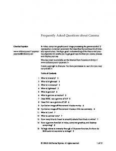
«interface» FigureSelectionListener
Object
«interface» DrawingEditor
JavaDrawApp
Figure 3: MicroDraw: inheritance hierarchy displayed for the object app:JavaDrawApp in the OOG. Participant 1 (P1) was not familiar with JHotDraw or any similar application. He was familliar with Java, but was not very familiar with the standard design patterns except for some of them. Finally, he was slightly familiar with UML. Participant 2 (P2) had looked at JHotDraw previously. He had intermediate Java skills and good knowledge of design patterns. He did not implement a GUI application before, but he had a good knowledge of Swing from his previous experience. Finally, he had a good knowledge of UML. Participant 3 (P3) was not familiar with JHotDraw, but he had three years of experience in Java. He was unfamiliar with design patterns. Finally, he had used UML before. Overall, the participants were unfamiliar with some of the advanced Eclipse features, e.g., to show the inheritance hierarchy.
3.3
Tools and Instrumentation
Participants were provided with the Eclipse IDE (Version 3.3) and were allowed to use any Eclipse feature. We used Camtasia to record the screen. Participants were asked to think aloud and prompted if they forgot to do so. We also captured the audio of the participants and the experimenter using Camtasia. We provided the participants with a hard-copy of a JHotDraw class diagram, and the interactive tool (Eclipse UML [5]) we used to generate the diagram. The participants were also provided with a hard-copy of a JHotDraw object diagram, and an interactive viewer for the object graph [23]. Finally, we provided the participants with tutorials by the JHotDraw original designers [6] (for the slightly older Version 5.1), a description of the design patterns used by JHotDraw [17], and the JavaDoc for JHotDraw. The study materials are available online [23]. The OOG viewer offers the following features (numbered below, and referred to in Section 4.2): • Display inheritance hierarchy (F1): the tool can display the inheritance hierarchy of the types of the field declarations that an object merges (Fig. 3); • Collapse/expand internals (F2): the hierarchical representation of the OOG allows a developer to collapse or expand the sub-structure or the internals of a selected object; • Control unfolding depth (F3): a developer can control the visible depth of the ownership tree; • Control object labels (F4): Each object in an extracted object graph represents at least one field or variable declaration in the program. An object might have multiple types, and the object graph uses one of those types as the label. The OOG can label objects with an optional field or variable name and an optional type name. The type used in the label can also include a labeling type (discussed below); • Set additional labeling types (F5): the object graph extraction non-deterministically selects a label for a given object o based on the name or the type of one of the references in the program that points to o. A developer can specify an optional list of labeling types for labelling objects. The tool adds the type decoration to an object’s label, if it merges at least one object of that type. For example, if the developer adds as a labeling type the FigureSelectionListener interface, the latter would appear as a decorator on the app:JavaDrawApp object in the OOG (Fig. 2(b)); 5
• Trace to code (F6): the tool can show the list of field declarations and their types that may refer to a given object in the diagram. In addition, the developer can trace from an object in the diagram to the corresponding lines of code; • Navigate (F7): the tool supports zooming in and out, panning, scrolling, and other standard operations; • Search tree (F8): the tool supports searching for an object in the ownership tree by type or field name; • Find label (F9): the tool supports searching for an element on the diagram by its label.
3.4
Tasks
We asked the participants to perform the following code modification tasks. Participant 1 was given four bug fixes: Task 1.1: Bug: “Keyboard delete not undoable:” if the user deletes a figure using the delete menu item, this action is undoable. But if he uses the delete key, the action cannot be undone. Task 1.2: Bug: “View-specific undo stack:” if the user opens two windows, modifies a drawing in one window, then switches to the other window (activates it), the undo command applies to the recently deactivated window. Task 1.3: Bug: “Undo ChangeAttributeCommand broken wrt GroupFigure:” if the user modifies a graphical attribute such as fill color on a shape which groups two or more figures, the change is not undone correctly. Task 1.4: Bug: “Undo delete doesn’t restore z-order:” deleting a set of figures, then undoing the delete, does not honor the original z-order of the figures. Participant 2 was given two feature requests: Task 2.1: Feature: “Prompt user on delete:” popup a message box: “Are you sure you want to delete: ‘figure name’” Yes—No. If yes, delete the figure. If no, cancel deleting the figure. The action should be undoable. Task 2.2: Feature: “Update the status bar when a figure is deleted:” whenever a figure is deleted the number of figures in the drawing should show on the status bar. This must work correctly with Undo/Redo. Participant 3 was given the same task as Participant 2: Task 3.1: Feature: “Update the status bar when a figure is deleted.”
3.5
Procedure
Our participants first worked through a brief tutorial on Eclipse code navigation features (such as using the call hierarchy, navigating to method declarations, and reference searches) to ensure they effectively used Eclipse. To simulate some of the architectural knowledge that an experienced developer might possess, we provided the participants with all necessery documentation that they might need to understand the desing and architecture of JHotDraw (See Section 3.3). Participants were then given a set of tasks and received a brief explanation on how to reproduce the bug using the JHotDraw user interface. This portion of the study lasted 10-15 minutes on average. The participants had as much time to understand the task description as they liked. Participants then navigated to the code described in each of the tasks which was also explained. They were allowed to spend as much or as little time as they wanted on each task. The participants were still working when their time expired. At the end of the two hours, participants were asked a series of exploratory interview questions about how they worked, what they found challenging, and how well they believed they did.
3.6
Analysis
We transcribed thinkaloud recordings and screen capture video into action logs consisting of a total of 1114 lines. Next, we used qualitative protocol analysis. We built a list of activities that we saw the developers 6
Figure 4: JHotDraw uses the Multiple Document Interface (MDI) style. engage in and coded what developers did using this model. Our analysis remained qualitative because the tasks varied slightly between developers. The coding model that we used to classify the different questions asked by developers during code modification tasks is shown in Table 1. We built this model based on specific keywords often used by developers when they think aloud. However, most of these codes are standard terms used in the literature (e.g. Is-A and Has-A relationships). For example, when the developer used the words ‘instance’ or ‘object’ or ‘reference’, we gave it the code Question/Fact Points-To or Question/Fact How-To-Get-X since obviously these are questions or facts about object relationships. Similarly if a developer used the terms ‘type’ or ‘class’ or ‘interface’ we coded them as questions or facts about classes. For example, if the developer used the term ‘inherits’ or ‘implements’ or ‘extends’, we gave it the code Question/Fact Is-A, which could be an object o of type X that is-a Y or a Class X that is-a Y.
4
Results
We first discuss the changes that the participants implemented. We then present our observations, and support them with evidence from the transcripts. Where applicable, we use a quote from a participant P , working on task T , using the notation (P, T ).
4.1
Code Changes
Participant 1 was able to complete three out of the four tasks. However, he did not do any code modification. This participant relied on his domain knowledge and asked high level questions about the design and architecture of the system. He also referred to the class diagram and the OOG viewer to help him understand the inheritance hierarchy especially for the third task.
7
Participant 2 was able to finish Task 2.1, but did not do any code modification. He spent almost 2 hours on the Task 2.2, without completing it. This participant was not fond of using external diagrams, and insisted on browsing the code. It also took him a long time to figure out where to place the code which was provided to him. His attempt at modifying the code was unsuccessful. Moreover, he proposed adding a lot of unnecessary code in order to implement the requested feature. Participant 3 was able to complete Task 3.1 and test the modification. The first attempt took him 1 hour, but it was a hack. So we asked him to redo the same task in a way that better fits JHotDraw’s design. He redid the task more quickly the second time. This participant referred to the class diagram and the OOG to understand composites and listeners.
4.2 4.2.1
Observations Value of Diagrams
High-level views of the program structure can be useful to developers making code modifications. The first canonical use case for a diagram is that of a new developer who knows nothing about the object structures. Since achieving that understanding by looking at the code may be difficult, the developer uses the diagram to obtain a high-level overview of the object structures at a glance. “I am not familiar with JHotdraw or any other similar application and I really don’t know where to start and I think this will be a pain” (P1, T1.1) “Could you give me a hint about what context the code came from?” (P2, T2.2)
The second use case is when a developer is using a diagram to locate where to put some code: “Until now, I was unable to find a place where the figure is being added [. . . ] and I am stuck. Eclipse does not help any more.” (P2, T2.2)
The following are observations related to object structures, organized hierarchically using a numbering scheme. 4.2.2
Object Structure
When working with object-oriented code, developers often ask questions about objects, and relations between objects. This observation is supported by several activities. We break down that observation into several observations that the evidence supports directly. Is part of. Developers ask questions or state facts about whether an object is logically or conceptually part of another object. “Maybe I would start with the Drawing object and that should have a list of listeners.” (P2, T2.2) “Okay what is figures? It is a Vector in CompositeFigure.” (P3, T3.1) “I should go to StandardDrawing and it has a set of listeners, fListeners.” (P3, T3.1)
Is owned. Developers ask questions or state facts about whether an object is strictly owned by, or encapsulated within another object. “[. . . ] the window itself has a reference to the UndoManager but you can’t tell from this diagram whether each window has its own UndoManager, or whether it is just one global manager” (P1, T1.2) “The difference would be: before, many windows shared one UndoManager, new version each window has its own UndoManager” (P1, T1.2)
In another case, the developer wondered whether several Drawing objects shared the same status bar object. “Why there is always one status bar? [. . . ] so you don’t want it to be with respect to each DrawingView [. . . ] so it [the status bar] is with the main window, it is not with the individual drawing” (P3, T3.1)
8
Is in tier. Developers ask questions or state facts about whether an object is in some tier. JHotDraw is implemented according to the Model-View-Controller style, though this is not represented by plain Java code. In fact, the suppressed annotations specify the architectural tiers directly within the code. Moreover, the static package structure says little about the runtime tiers. The developers were often wondering where to get hold of the “document” or where to get hold of the “view”. “And where is my Document? Application? Figure? Drawing? So that has a list of Figures. So let’s try to drill into that since we did not have any success here [. . . ] I am looking for the Drawing object [. . . ] DrawingChangeEvent [. . . ] sorry, I just got distracted [. . . ] getting a little vague at this point, that takes me back to Drawing.” (P2, T2.2) “I’m not a big design document type person, but what I would be interested in is looking in the code to try to understand where are the view and model” ibid
Composites. Implementations of the Composite design pattern seem hard to understand with only a class diagram. For example, in JHotDraw, StandardDrawing extends CompositeFigure to enable nesting a Drawing inside another Drawing. This is in addition to a Drawing object having a list of constituent Figure objects. The developers were not able to understand these relations from looking at the class diagram alone. The OOG displays these relations much more explicitly. By expanding the sub-structure of the Drawing object (F2), the developer could see the Vector of Figure objects inside the Drawing object. In turn, the Vector object points to the Figure object, which is a sibling of Drawing. In addition, the OOG viewer can also display a partial class diagram (F1), which can also confirm that StandardDrawing is-a Figure. As an aside, this finding is interesting because it slightly contradicts the design. There is only a brief mention of it in the Release Notes of Version 5.1. Moreover, in the framework package, interface Drawing does not extend Figure! Indeed, the JHotDraw designers explicitly asked to “not commit to the CompositeFigure implementation since some applications need a more complicated representation” [6, Slide #16]. How to get object x. Developers ask questions or state facts related to whether they already have a reference to an object o or need to somehow obtain such a reference. “How I will get hold of the DrawingEditor object? [. . . ] basically I need to know the instance of the current window” (P3, T3.1) “as soon as I am inside the listener function [. . . ] I get the Figures but I need to show the status.” (P3, T3.1) “[. . . ] how to get that Drawing object” (P2, T2.2)
How to go from x to y. Developers ask questions or state facts related to navigating the object structure, to go from object X to object Y . “I know I need to get the view from here so how do I do that?” (P3, T3.1) “Let’s say I am in the StandardDrawing class and I want the JavaDrawApp object which is a DrawingEditor [. . . ] what would save me a lot of time is to say now I am at the Drawing and I want to go to the DrawingEditor, show me my options.” (P2, T2.2)
Cardinality. Developers ask questions or state facts related to the cardinality of an object relation (1-to-1 or 1-to-many). “Also I would like to know the cardinality so Window has one or more StandardDrawingViews.” (P1, T1.2) “Well, I would change the cardinality from multiple Windows, one UndoManager to multiple Windows, multiple UndoManagers.” (P1, T1.2) “The class diagram says that the DrawingEditor has one DrawingView and the StandardDrawingView may or may not have a Drawing [. . . ] the visual syntax does not tell you if there is a pointer to one or more.” (P1, T1.2)
Navigation. The developers navigated the object structure using several of the features of the interactive OOG viewer (Section 3.3), e.g., to show or hide the internals of a selected object (F2), or to trace from an object or edge on the diagram to the code (F6). In some cases, the developer was too intimidated by the user interface of the OOG viewer, and the experimenter stepped in to assist. 9
4.2.3
Object + Type Structure
When working with object-oriented code, developers often switch between asking questions about the type structures and about the object structures. Indeed, the type and the object structure are complementary. For “is a” type questions, it is often hard to separate the cases where the developer is referring to an Object a of type A which extends from or implements type X, as opposed to simply referring to a class C which extends from or implements type Y . The developer often needed access to the code structure, even when looking at the object structure. The OOG viewer has several features to expose some information about the code structure in the object structure in various ways (See Section 3.3). First, the label of each object in the OOG includes some type information (F4). Second, the developer can select additional types of interest, typically, the listener interfaces (F5). Third, the developer can display partial class diagrams (F9). Finally, the developer can trace each element in the OOG to the code (F6). Is a. The developer often asked questions or stated facts related to the Is-A relationship. He often answered these questions by navigating the code structure. In many instances, the developers asked questions such as “who implements X”, where X is some type, and used the Eclipse features to examine the type hierarchy. Is subtype of. When developers search for objects of type T , they must look for all objects of type T 0 where T 0 is a subtype of T . In order to achieve abstraction, the OOG can merge several objects into one canonical object. 4.2.4
Object Identity
When working with object-oriented code, developers often need to distinguish between different instances of the same type. To make informed code changes, the developers must understand the following object relationships. One JavaDrawApp instance can display multiple Drawing objects (documents). In turn, each document can be represented using multiple views (DrawingView). Having multiple views of the same document allows the users to view independently two parts of the same document, or scroll or zoom the views separately. Launching the application creates a new JavaDrawApp object. Every time the user invokes the “File—New” or the “File—Open. . . ” menu item, a new Drawing object is created. By default, a new DrawingView object is automatically created to display the Drawing. When the user creates additional views of the same document by selecting an active view of a document, then using the “Window—New View” menu item, an additional DrawingView object is created, but shares the same underlying Drawing object. Because JHotDraw supports the Multiple Document Interface (MDI) style of interaction, the user can create or open multiple documents at once (Fig. 4). Observers. Implementations of the Observer design pattern are hard to understand based on the static code structure alone. In object-oriented design patterns, much of the functionality is determined by what instances point to what other instances. For instance, in the Observer design pattern [7, p. 293], understanding “what” gets notified during a change notification is crucial for understanding the system. But “what” does not usually mean a class, it means a particular instance. For example, in Fig. 4, the objects drawingView11 and drawingView12 must listen to notifications from the object drawing1 only, and must not listen to any notifications from the drawing2 object. Listener interfaces are often implemented by different types, which in turn are instantiated in different places in the program. For example, in JHotDraw (and MicroDraw), both Command and DrawingEditor implement the FigureSelectionListener interface. Instances of DrawingEditor are in the MODEL tier, and instances of Command are in the CONTROLLER tier (Fig. 2(b)). The complexity increases significantly when multiple listener interfaces are present. For example, JHotDraw has no fewer than six application-specific listener interfaces, in addition to the listener interfaces from the libraries it uses. “So something had to fire off the view update, so what I am thinking about is that all registered observers are notified if the drawing view has been changed.” (P2, T2.2)
10
Figure 5: Types and frequency of questions asked by developers during code modification tasks. “So there has to be some kind of a listener . . . FigureChangeListeners?” (P3, T3.1) “DrawingView itself is a DrawingChangeListener. Okay” (P3, T3.1) “But how can I get the listeners over there, I need the listeners in the orphan() method. If I have the listener I can do everything else.” (P3, T3.1)
At the end of each experiment, we asked the participants if they could understand listeners by looking at the class diagram. In particular, we asked one developer if the class diagram helped him understand that a Drawing has a list of DrawingChangeListeners, he said: “Not directly. It is hard to find but I referred to [the class diagram] because I am used to it, but if I use this [object] diagram more and more, I will get used to it.” (P3, T3.1)
Related to the above question of distinguishing between instances of the same type, is the question of identifying references to similar or identical objects. May alias. Developers ask questions or state facts about whether two references may or may not alias, i.e., refer to the same object at runtime. “So I have different selections in the different views.” (P2, T2.2) “Both of them are two views on the same Drawing, but if there are two windows. . . ” (P3, T3.1)
4.2.5
Summary
We summarize the types and the frequency of the various facts stated or questions asked by the developers in Fig. 5. 4.2.6
Additional Observations
Points to. Developers often ask questions or state some facts about whether an object points or refers to another object. “[. . . ]basically the DrawingEditor has a reference to every Drawing object” (P2 T2.2)
11
“[. . . ]the Command knows about the DrawingEditor” (P2 T2.2) “[. . . ]only commands seem to be able to get to the editor and this thing [StandardDrawing] has no concept of Command” (P2 T2.2)
Has Label. Developer sometimes ask questions about the label of an element in the diagram. “[. . . ]yeah the Window is the JavaDrawApp, but I am curious why it shows the label as window?” (P1, T1.2) “[. . . ]Is there a renaming type refactoring you can do to lower the impedance of the source code?[. . . ] if this name is actually depicted in the code it would help, and like Figure right now is overloaded with Drawing. For me, Figure is a part of the entire document not the shape” (P2 T2.2)
Diagrams. During the experiment developers often asked questions or stated some facts about the object diagram or the UML class diagram. Developer may have been confused by the object diagram notation, which is novel and different from UML. “Does these relations, I mean the extends and the implements just as in the UML diagram? I mean the dotted and the solid lines[. . . ]so it does not matter if this implements or extends?” (P3, T3.1) “[. . . ] so this is a call graph type thing and this is inheritance? [. . . ] what are the arrows?[. . . ]these are method calls?” (P2, T2.2) “[. . . ] can you tell me what is this incoming arrow in the UndoManager?[. . . ]that means that someone has a reference to the UndoManager. It looks there are two. What does the red imply?” (P2, T2.2)
Developers wanted to see new features in the OOG viewer: “see the CRC had a sentence description of what the object was. Something like that would lower the learning curve or the table of contents or glossary would work” (P2, T2.2) “Can you explain this notation[lent.Main.Model:Drawing] [. . . ] it will be easier for me to interact with the tool if I found the tool is answering the questions that I am trying to ask and the visual display is giving me a global view when I am actually asking a specific question which is taking me from point A to point B and less rich display of information may be more attractive” (P2, T2.2) “this is a Directed Graph right? and so if you let me pick point A and point B and then say: what are the candidates to get from here to here that would be kind of an interesting model” (P2, T2.2) “I wonder how you do this navigation: that I am performing this type of query in the tool and get this result that allows me to make this modification so what would save me alot of time is to say now I am at the Drawing and I want to go to the DrawingEditor show me my options [. . . ] basically you do a query from this kind and have the tool show you the hops” (P2, T2.2) “[. . . ] the other thing that would be useful if you have a history” (P2, T2.2)
Developers identified some issues in the object diagram that decreased its usefulness. “[. . . ] the visual display is giving me a global view when I am actually asking a specific question which is taking me from point A to point B and less rich display of information may be more attractive” (P2, T2.2) “[. . . ]if it is color-coded, probably that might have been useful. Everything is black and I dont know where I’m going” (P3, T3.1)
Developers stated a fact that the object diagram is missing some information such as cardinality at the object level: “so when we were talking about having multiple or single undo manager or filtering undo manager this diagram does not seem to help you in representing either of these changes, especially if you are comparing against somehting like UML, which at least already has some of that, but probably it is clear that there was some motivation why you created the tool in the first place. There is some case where you need to know the instance stuff and UML just doesn’t help you” (P1, T1.2)
12
Developers found some features in the OOG viewer to be useful: • Trace to code. “[. . . ] this shows that DrawApplication has an UndoManager field, this is really interesting so there is this private UndoManager within this DrawApplication” (P1, T1.2) “yeah, this [trace to code] is handy” (P2, T2.2) “that is good, I mean when you clicked on the arrow and you said: show me the relation and then you went to the line of code. That is cool” (P3, T3.1)
• Architectural tiers. “The tiers concept in the diagram helps but I assume this was created just by code or some manual input? Now from those tiers I realize that I should not make the changes in the VIEW I should do them in the MODEL component because I think I was doing the change in the surface” (P3, T3.1)
• Search ownership tree. “what i am wondering if you did a simple dialog box and where you filled in the first field and then you basically did the enumerations as a drop down list of the second field or something like that” (P2, T2.2)
The developer found that this feature is useful and that it would be more useful if it is showing him point A to point B filtered by point A, and then he could scan the destinations and look for point B. “[. . . ]yeah, or even if you are willing[. . . ]because this is a directed graph, right?[. . . ]if you let me pick point A and point B and then say: what are the candidates to get from here to here that would be kind of an interesting model” (P2, T2.2)
Object merging. Developers seem to have difficulty with object merging in the object diagram. In some cases, the labels were counter-intuitive and may have led to confusion and reduced the diagram’s usefulness. “[. . . ]but I am curious why it shows the label as ’window’ ? [. . . ] so the fact that window is called Window instead of JavaDrawApp make me think that there are multiple things here other than JavaDrawApp which is taking the least common denominator ” (P1, T1.2)
That questions about Object Merging occur only a few times is actually interesting. May mean that abstraction works, and developers does not have many questions about it.
5 5.1
Discussion Limitations
Our study observed only 3 participants and did so on tasks specifically designed to provoke developers to think about object structure. Even the codebase itself had been specifically chosen to have many interesting examples of design patterns, and relationships between objects. Thus, while our results demonstrate that developers do ask questions about class and object structure in such situations, they say little about how frequently these questions occur in practice. While the experimenter asked questions to direct the participants during the study to make sure they are not distracted, we believe this prompting mostly helped participants get to questions about object structure faster, rather than leading them to ask questions they would otherwise have been able to avoid. Finally, both the class and object structure diagrams were produced by the experimenter by hand to illustrate architecturally important information. Diagrams in practice might not focus as much on such relationships.
5.2
Usability Issues
The study identified a number of usability issues that may have reduced the usefulness of the object diagrams to developers. Part of the challenge is that developers are not familiar with notations that are different from the standard code structure notations such as UML. As a result, diagrams of the runtime structure are often harder to understand and interpret than UML diagrams, as confirmed by others [8]. 13
One developer said that “the problem with the tool in its current state is that the navigation is subtle enough that I did not have a lot of time and confidence from watching you navigating that I could navigate. On the other hand it is a new type of tool” (P2, T2.2) Another developer said that he could not make the best use of the tool because of the cluttered edges in the object diagram. Finally, one of the developers wanted the object diagram to show the cardinality on the object relations.
6
Related Work
The research literature has abundant theoretical evidence that runtime structure is important. But the lack of tools that extract statically meaningful object graphs made it difficult to empirically evaluate the usefulness of object structure in the context of coding activities. Studies of developer questions. Recently, a few studies have observed developers during coding activities to find questions about code that developers ask. Ko found questions developers ask when writing code, submitting changes, triaging bugs, reproducing failures, understanding execution behavior, reasoning about design, and maintaining awareness [19]. Sillito focused more specifically on questions about code and found that developers ask questions about relationships between types or objects including composition and inheritance relationships [26]. But they did not attempt to distinguish questions about class relationships from questions about runtime object structure. Empirical evaluation of design diagrams. Several researchers have evaluated empirically the usefulness of various object-oriented design diagrams, e.g., [9, 4, 3]. Unfortunately, these evaluations focus mostly on class diagrams, or partial runtime views such as sequence diagrams. This is partly because object structure has been difficult to obtain statically using previous technology. More recent empirical evidence is paying greater attention to the importance of understanding the runtime structure of an application. Lee et al. [21] report on an empirical study where a participant expressed the need to understand “how objects connect to each other at runtime when I want to understand code that is unknown: an object diagram is more interesting than a class diagram, as it expresses more how [the system] functions”. Our previous evaluation of OOGs. In previous work [1], we conducted a field study to evaluate if an outside developer understood OOGs. However, we did not use the object diagram to perform any code modification tasks. Program understanding. Gamma et al. were among the first to emphasize the challenges of understanding the runtime structure “An object-oriented program’s runtime structure often bears little resemblance to its code structure. The code structure is frozen at compile-time; it consists of classes in fixed inheritance relationships. A program’s runtime structure consists of rapidly changing networks of communicating objects. In fact, the two structures are largely independent. Trying to understand one from the other is like trying to understand the dynamism of living ecosystems from the static taxonomy of plants and animals, and vice versa” [7, p. 22]. Many researchers have confirmed empirically these challenges. For example, Kirk et al. state that objectoriented frameworks pose particular program understanding challenges, and emphasize that “understanding the dynamic behavior of a framework is more challenging, particularly given the separation of the static and dynamic perspectives in the object-oriented paradigm” [18]. Shull et al. concur that both “the static and dynamic structures must be understood and then adapted to the specific requirements of the application [. . . ] For a developer unfamiliar with the system to obtain this understanding is a non-trivial task. Little work has been done on minimizing this learning curve” [25]. Design patterns. In their landmark book, Gamma et al. generated manually both class diagrams and object diagrams to explain several of the structural design patterns, such as Proxy, Mediator and Composite [7]. Riehle proposed explaining the design patterns based on the class structure and evaluated his approach on JHotDraw [24]. 14
Dynamic analysis. Several approaches used dynamic analysis [20, 27] to generate high-level views for program understanding. But an object diagram extracted using a dynamic analysis reflects only the use cases that are exercised, and the input. Moreover, it may not reflect important objects or relations that show up in other executions. As a result, such a diagram may be not be a trusted source of information for all code modification tasks. Class structure questions. Mandelin et al. [22] proposed an approach and a tool, Prospector, to help developers answer questions about the type structure. Prospector, however, cannot distinguish between two different instances of the same type in different contexts.
7
Conclusions
We conducted an exploratory study to identify some of the questions about objects and their relations that developers ask during code modification tasks. The study gave us insights into the questions that developers ask, and how tasks could be redesigned to focus specifically on the questions that are hard to answer using only the code structure. In addition to the developer questions, we identified some usability challenges in the current tools, which may lower their usefulness to developers. Once we address some of these issues, we will conduct additional, evaluative studies.
Acknowledgements The authors thank Brad Myers and Jonathan Aldrich for their useful advice on designing the exploratory study. Thanks to Talia Selitsky and the rest of the SEVERE group for their comments on improving this paper.
15
References [1] M. Abi-Antoun and J. Aldrich. A Field Study in Static Extraction of Runtime Architectures. In PASTE, 2008. [2] M. Abi-Antoun and J. Aldrich. Static Extraction and Conformance Analysis of Hierarchical Runtime Architectural Structure using Annotations. In OOPSLA, 2009. [3] C. J. Bennett, D. Myers, M.-A. Storey, D. M. German, D. Ouellet, M. Salois, and P. Charland. A Survey and Evaluation of Tool Features for Understanding Reverse-Engineered Sequence Diagrams. J. Softw. Maint. Evol., 20(4), 2008. [4] W. Dzidek, E. Arisholm, and L. Briand. A Realistic Empirical Evaluation of the Costs and Benefits of UML in Software Maintenance. TSE, 34(3), 2008. [5] Eclipse UML. http://www.omondo.com/, 2006. [6] E. Gamma. Advanced Design with Patterns and Java (Tutorial). In European Conference on Java and Object Orientation (JAOO), 1998. JHotDraw v. 5.1. [7] E. Gamma, R. Helm, R. Johnson, and J. Vlissides. Design Patterns: Elements of Reusable ObjectOriented Software. Addison-Wesley, 1994. [8] J. C. Grundy and J. G. Hosking. Softarch: Tool Support for Integrated Software Architecture Development. J. Softw. Eng. Klndg. Eng., 13(2), 2003. [9] I. Hadar and O. Hazzan. On the Contribution of UML Diagrams to Software System Comprehension. Journal of Object Technology, 3(1), 2004. [10] D. Jackson and A. Waingold. Lightweight Extraction of Object Models from Bytecode. TSE, 27(2), 2001. [11] JHotDraw. www.jhotdraw.org, 1996. Version 5.3. [12] Bug #726304: Deleting a figure does not notify FigureChangeListeners. sourceforge.net, 2006. [13] Bug #675587: Undo ChangeAttributeCommand broken /wrt Group Figure. sourceforge.net, 2006. [14] Bug #669421: Undo restores Dependent figures, regardless if deleted. sourceforge.net, 2006. [15] Bug #649258: Undo delete doesn’t restore z-order. sourceforge.net, 2006. [16] Bug #594961: keyboard delete not undoable. sourceforge.net, 2006. [17] JHotDraw Pattern Language. softarch.cis.strath.ac.uk/PLJHD/Patterns/JHDPatternIndex. html, 2006. [18] D. Kirk, M. Roper, and M. Wood. Identifying and Addressing Problems in Object-Oriented Framework Reuse. Empirical Software Engineering, 12(3), 2006. [19] A. J. Ko, R. DeLine, and G. Venolia. Information Needs in Collocated Software Development Teams. In ICSE, 2007. [20] D. Lange and Y. Nakamura. Interactive Visualization of Design Patterns Can Help in Framework Understanding. In OOPSLA, 1995. [21] S. Lee, G. Murphy, T. Fritz, and M. Allen. How Can Diagramming Tools Help Support Programming Activities? In VL/HCC, 2008. [22] D. Mandelin, L. Xu, R. Bodik, and D. Kimelman. Jungloid mining: helping to navigate the API jungle. In PLDI, 2005. [23] Exploratory Study: Online Appendix. www.cs.wayne.edu/~mabianto/oog_study1/, 2010. [24] D. Riehle. Framework Design: a Role Modeling Approach. PhD thesis, Federal Institute of Technology Zurich, 2000. [25] F. Shull, F. Lanubile, and V. R. Basili. Investigating Reading Techniques for Object-Oriented Framework Learning. TSE, 26(11), 2000. [26] J. Sillito, G. Murphy, and K. D. Volder. Asking and Answering Questions during a Programming Change Task. TSE, 34(4), 2008. [27] R. J. Walker, G. Murphy, B. Freeman-Benson, D. Wright, D. Swanson, and J. Isaak. Visualizing Dynamic Software System Information through High-Level Models. In OOPSLA, 1998.
16
A
Tools and Instrumentation
The OOG Viewer tool used in the study is shown in Fig. 6.
B
Coding Model
The coding model used to classify the types of questions that developers ask is shown in Table. 1
Figure 6: OOG viewer tool used in the study.