QWIP Chip Dual-Color and Multi-Color FPAs for Military Applications B. McQuistona, E.Choa, W.Lima, Sir B. Rafola Dr. S. D. Gunapalab, S. V. Bandarab, J. K. Liub a QWIP Technologies, Inc., 2400 Lincoln Ave, Altadena CA 91001; b Jet Propulsion Laboratory, Center for Space Microelectronics Technology, California Institute of Technology, Pasadena, CA 91109 USA ABSTRACT Quantum Well Infrared Photodetectors (QWIPs) based infrared focal plane arrays (FPAs) are commercially available in the single color. QWIP Technologies, Inc. provides a number of QWIPCHIPTM FPAs available in the single-color, dual-color and even multiple-color, as well as varieties of physical formats in the infrared range. In this paper, we discuss the research and development efforts currently ongoing at QWIP Technologies on dual-color, visibleNIR/LWIR FPAs, and the development of a four-color QWIP-based FPA. These multicolor systems are being developed to meet the needs of a number of military applications including land mine detection. Land mines inhibit the safe movement of troops and produce chaos in countries struggling for socio-economic stability long after the cessation of hostilities. This paper will describe the efforts to develop a near multi-color QWIP sensor for mine detection. The core of the discussion will include highlights of a two-color LWIR QWIP sensor system designed to provide uniform, high spatial resolution, multi-color co-registered imagery and possess negligible spectral cross-talk. Through these efforts, The Defense Advanced Research Projects Agency (DARPA) is completing the development of a visible/infrared mine detection system, which when deployed on an airborne platform, would increase the war fighting effectiveness has sponsored the current developments. Keywords: Infrared, QWIP, imaging, multispectral, mine detection, long wave infrared
1.0 INTRODUCTION High quality focal plane array (FPA) detectors sensitive to either visible or infrared light have been available for many years. More recently, a few government and commercial organizations have developed prototype infrared detectors sensitive to several infrared wavelengths at once. By contrast, many human operators have difficulty in recognizing targets and their environments by their infrared signature alone. Therefore, having simultaneous visible images that supply a contextual framework can create a great advantage. Visible images are also crucial in maximizing daylight operations capability. There are many applications in the U.S armed forces that would benefit from using a multi-band visible infrared sensor array. For example: Army • A handheld multi-band camera would increase battlefield surveillance capabilities. • A multi-band infrared commander’s periscope would provide increased target identification capabilities, especially at night. Such a system would also be able to detect and identify cold body threats from above. Navy • A multi-band based fire control system would have superior threat identification abilities. • A multi-band camera is more capable of identifying colder threats at sea than existing systems. A compact QWIPTECH system would be especially suitable for optronic masts and periscopes. Air Force • A multi-band system could quickly identify incoming missile threats and would not be as susceptible to confusion by clutter. • A multi-band system would have superior target identification and damage assessment capabilities.
Electro-Optical and Infrared Systems: Technology and Applications, edited by Ronald G. Driggers, David A. Huckridge, Proc. of SPIE Vol. 5612 (SPIE, Bellingham, WA, 2004) · 0277-786X/04/$15 · doi: 10.1117/12.579456
51
• •
A multi-band camera with sensitivity up to 20µm would be effective at identifying missiles during both the boost and coasting (or cruise) phases. A simultaneous and pixel co-located mid-wavelength and long-wavelength infrared (LWIR) dualband imager would be useful in accurately determining the temperature of objects without having any knowledge of their emissivities.
The quantum well infrared (IR) photodetector (QWIP) has been in development with leading world research institutes for over 20 years. Today, this research has advanced the state of the art in IR FPA technology. QWIPs utilize photoexcitation of electrons, commonly known as the theory of a particle in the box, to develop the next generation of IR FPAs. QWIP Technologies, Inc. (QWIPTECH) and the CALTECH Jet Propulsion Laboratory (JPL) have worked with the Defense Advanced Research Projects Agency (DARPA) to develop this technology into a multi-color, large format FPA. QWIPTECH and JPL have developed a four-color FPA system that could be the basis for the next generation of imaging sensors. Our work has been to rely on our already well-developed knowledge of QWIPs and pursue advanced research in this effort to take this work into a next generation technology.
2.0 CURRENT STATE OF THE ART Quantum wells detect infrared radiation according to the well-known particle in the box scenario. Photons excite an electron from the ground state to the first excited state. These charge carriers escape from the quantum well and are collected as a photocurrent. The first QWIPs were bound to continuum devices, in which the first excited state is a continuum level approximately 10meV above the well top. The bound to quasi-bound QWIPs utilized by QWIPTECH have the first excited state positioned exactly at the well top. In these bound to quasi-bound devices, the barrier to thermionic emission is approximately 10meV greater and the dark current noise is reduced by a factor of ~6 than in bound to continuum detectors. By stacking up to 50 bound to quasi-bound structures together it is possible to build a highly sensitive but low noise detector. QWIPs offer greater flexibility than extrinsically doped semiconductor infrared detectors because the wavelength of the peak response and cutoff can be continuously tailored by varying the layer thickness (quantum well depth) and barrier composition (barrier height). The specific wavelength flexibility depends on the material used to construct the well. The lattice matched GaAs/AlxGa1-xAs material system is an excellent choice for creating a quantum well structure. It is possible to design a QWIP structure tunable over a wavelength range from 5µm to greater than 20µm. This wavelength range can be extended down to 3µm by doping the well with indium, which lowers the ground state energy. QWIPTECH can easily construct a GaAs/AlxGa1-xAs-based QWIP structure using established semiconductor fabrication techniques. Due to quantum selection rules, quantum wells are not sensitive to normally incident radiation. To surmount this difficulty, QWIP FPA’s have a reflective grating etched onto their front side. Light enters the FPA via backside illumination, passes through the well, and is then reflected at a non-normal angle by the grating. A portion of the electric field is now parallel to the superlattice growth direction i.e. normal to the layers, making it susceptible to absorption. The photon excites an electron in the well creating a photocurrent. This current is then read-out using silicon based circuitry that is bump bonded onto the front side of the FPA.
2.1 MULTICOLOR DEVICES In various IR imaging applications, an additional color, i.e. spectral sensitivity, is of great demand, and provides enormous imaging enhancement. The narrow spectral band nature of QWIP detector technology has enabled the feasibility of simultaneous sensitivity to different IR bands of common interest (SWIR, MWIR, LWIR and VLWIR) or multi-peaks within the same band of interest. The ability to tune the spectral bandwidth from narrow to wide and the peak wavelength anywhere between the MWIR up to VLWIR and beyond are the greatest advantages of QWIP detector technology. To implement the visible and LWIR imager, QWIPTECH uses QWIP detectors with spectral bandwidth in LWIR sensitivity while adding the visible/NIR device of a GaAs PIN photodiode. The design parameters of LWIR QWIP are similar to our standard LWIR detectors, which include the well, barrier, doping profile, and grating parameters. For GaAs PIN photodiode we turn to an extensively published result from solar cells research on GaAs photodiode. An
52
Proc. of SPIE Vol. 5612
added advantage in utilizing GaAs/AlGaAs based material is the absent of lattice mismatched between the PIN diode and LWIR.
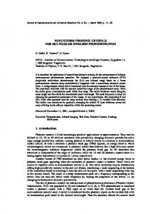
2.2 APPLICATIONS AND COMMERCIAL PRODUCTS There are many applications that require long wavelength, large, uniform, reproducible, low cost, stable, and radiationhard IR FPAs. One particular application is the detection of landmines. Landmines are widely proliferated due to its low cost. However, the cost and effort it requires to neutralize landmines amount from several to hundreds of times more expensive than to deploy them. QWIPTECH and JPL under a DARPA funded effort are working on a dual-color pixel co-located simultaneously readable QWIP based imaging array. QWIPTECH and JPL have developed several types of QWIP based FPA. QWIPTECH is currently producing midformat 320x256 LWIR devices, a large format 640x512 and the 1024 x 1024 QWIPCHIPTM FPA products. (Figure 1)
Figure 1: QWIPTECH family of products.
QWIPTECH and JPL have developed a dual-color LWIR QWIP detector. This detector possesses an interlaced structure that uses even rows for one color and odd rows for the other color. Such interlaced FPAs can be bonded with standard read out devices. QWIPTECH and JPL have also recently completed for a four color MWIR/LWIR array.
3.0 THEORY OF MINE DECTECTION Soil on the ground can be categorized into large/coarse particles (> 65 µm) and small/fine particles (< 65 µm). Explained by the Reststrahlen effect, the small particles show much less spectral contrast in the 7.5 µm to 12 µm IR wavelength range. The emissivity curves of large and small particles are shown in Figure 2. Most of the larger grains below the soil surface (several millimeters range) have small particles coating on them. However, due to weathering effects (e.g. rains winds, etc.), the small particles tend to be washed off the large particles that are exposed or close to the surface of the soil so the soil in the proximity of the surface tend to be composed of mainly large particles while the soil under the surface contains both large and small particles. Since the burying of landmines usually involves soil mixing exceeding several millimeters of depth, the surface areas of disturbed soil after the burial of landmine usually are composed of both large and small particles. The theory of uncovering the landmines is then based on detecting the difference in the emissivity of the disturbed soil and the undisturbed (Figure 3).
Proc. of SPIE Vol. 5612
53
Figure 2: The emissivity curves of fine and coarse particles
Figure 3: The emissivity curves of disturbed and undisturbed soils
54
Proc. of SPIE Vol. 5612
3.1 SENSOR DEVICES From Figure 3, the emissivity difference between disturbed soils and the undisturbed is noticed to be most significant at around 9.2 µm; hence, the dual-color QWIPTECH QWIPCHIPTM FPA is designed to have one peak at 9.2 µm in order to obtain the strongest signal. The other peak is chosen to be around 12 µm for the relative negligible difference in emissivity between two soil types and will serve as a reference point. Another reason is that it is far enough from 9.2 µm to minimize the spectral crosstalk between the two wavelengths. The final camera system features a 320x256, dual-color, co-registered QWIP FPA with 40 µm pixel pitch and two peaks at 9.2 µm and 12 µm respectively, as well as a COTS (commercial off-the-shelf) Texas Instrument TC253SPD, 656x496 CCD imaging array with 7.4 µm pixel pitch and sensitivity from DUV (deep ultraviolet) to NIR (near infrared).
4.0 QWIPTECH DUAL-COLOR FPA For the application of mine detection, the LWIR peaks occur at the 9.2 µm and 12 µm respectively. The LWIR QWIP structure has been designed to have a bound-to-quasi-bound intersubband absorption peak at 9.2 µm. This MQWs (multiple quantum wells) structure is then sandwiched between GaAs top and bottom contact layers doped with n = 5 x 1017 cm-3, and has been grown on a semi-insulating GaAs substrate by MBE. Then a 300 Å Al0.3Ga0.7As stop-etch layer and a 1.0 µm thick GaAs cap layer were grown in situ on top of the device structure. GaAs wells of the LWIR were doped with n = 4 x 1017 cm-3. All contact layers were doped to n = 5x1017 cm-3. Figure 4 shows the responsivity spectrums of the 9.2 µm band. Based on single element test detector data, the LWIR detectors show BLIP at temperature of 68 K for a 300 K background with f/2 cold stop. Figure 5 shows the dark current vs. photocurrent for the 9.2 µm band. Figure 6 shows the dark current data. Q W IP S p e c tr a l R e s p o n s e v s B ia s
Dark Current / Photo Current Vs T (9.2 micron QWIP, 300 K , f/2)
0 .8 0 1 0 -0 .5 v 1 0 -1 .5 v
0 .6 0
1 0 -2 v
0 .5 0
1 0 -3 v
0 .4 0
ID (Amp/pixel)
RESPONSIVITY (A/W)
0 .7 0
4 V
0 .3 0 0 .2 0 0 .1 0
1.E-08 Iphoto
1.E-10 1.E-12
0 .0 0 4
5
6
7
8
9
10
W a v e le n g th (u m )
11
12
1.E-14 40 50
60 70
80 90
Temperature (K)
Figure 4: 9.2 micron peak responsivity Figure 5: Dark current vs. photo current for the 9.2 µm QWIP at various
Proc. of SPIE Vol. 5612
55
Dark Current Vs Bias Voltage A= 3.14e-4 cm-2
Dark Current / Photo Current Vs T (12 micron QWIP, 300 K , f/2)
1.E-05
Current (A)
1.E-07
40K 50K 60K 70K 80K
1.E-08 1.E-09 1.E-10 1.E-11
ID (Amp/pixel)
1.E-06
1.E-08 Iphoto
1.E-10 1.E-12 1.E-14
1.E-12
40
1.E-13 -5
-3
-1
1
3
50
60
70
80
90
T emperature (K)
5
BIAS (V)
Figure 6: Measured dark current curves for the 9.2 µm QWIP detectors.
Figure 8: Dark current vs. photo current for the 12 µm QWIP at various temperatures.
Spectral Response vs Bias 2.00
RESPONSIVITY (A/W)
30K 40K 50K 60K 70K 80K 90K 100K
1.E-03 1.E-05 1.E-07 1.E-09 1.E-11 1.E-13
1.80
Bf-1v
1.60
Bf-2v
1.40 1.20
Bf-3v
1.00
Bf-4v
0.80 0.60 0.40 0.20 0.00 9
10
11
12
13
14
Wavelength (um)
Fig 7: Responsivity curves for 12 um QWIP under different bias conditions.
56
QWIP (12um) Dark Current A = 5.5e-4 cm-2
Current (A)
The VLWIR (very long-wave infrared) QWIP structure has been designed to also have a bound-to-quasi-bound structure with a peak wavelength at 12 µm. This MQWs (multiple quantum wells) structure is grown by MBE. Figure 7 shows the responsivity curves of the 12 µm band. Based on single element test detector data, the VLWIR detectors show BLIP at temperature of 58 K for a 300 K background with f/2 cold stop. Figure 8 shows the dark current vs. photocurrent for the 12 µm band. Figure 9 shows the dark current data.
Proc. of SPIE Vol. 5612
1.E-15 -5
0
5
BIAS (V)
Figure 9: Measured dark current curves for the 12 um QWIP detector at various temperatures.
5.0 640 x 512 PIXEL FOUR-BAND QWIP FOCAL PLANE ARRAYS 5.1 VERTICALLY INETGRATED FOUR-COLOR QWIP DEVICE This four-band vertically integrated device structure was achieved by the growth of multi-stack quantum well infrared photodetector (QWIP) structures separated by heavily doped n+ contact layers, on a GaAs substrate. Device parameters of each QWIP stack were designed to respond in different wavelength bands. Figure 10 shows the schematic device structure of a four-color QWIP FPA. A typical QWIP stack consists of a multi-quantum-well (MQW) structure of GaAs quantum wells separated by AlxGa1-xAs barriers. The actual device structure consists of a 15 period stack of 4-5 µm QWIP structure, a 25 period stack of 8.5-10 µm QWIP Light Coupling structure, a 25 period stack of 10-12 µm QWIP structure and a Gratings/Au Metal 30 period stack of 13-15.5 µm QWIP structure. Each Contacts 640 photosensitive MQW stack was separated by a heavily doped n+ (thickness 0.2 to 0.8 µm) intermediate GaAs contact layer (see Fig. 10). Since the dark current of this device structure is dominated by the longest wavelength portion of the device structure, the VLWIR QWIP structure has been designed to have a bound-to-quasibound intersubband absorption peak at 14.0 µm. Other QWIP device structures have been designed to 128 Indium Bump 128 have a bound-to-continuum intersubband absorption process 128 128 because the photocurrent and dark current of these devices are Fig. 10: Layer diagram of the four-band QWIP device relatively small compared to the VLWIR device. This whole structure and the deep groove two-dimensional four-band QWIP device structure was then sandwiched between periodic grating structure. Each pixel represents 0.5 µm GaAs top and bottom contact layers doped with n = 5 x a 640x128 pixel area of the four-band focal 1017 cm-3 and was grown on a semi-insulating GaAs substrate by plane array. MBE.
5.2 640 X 512 PIXEL FOUR-COLOR SPATAILLY SEPARATED FOCAL PLANE ARRAY In this section, we discuss the fabrication and test results of the 640x512 pixel monolithic spatially separated four-band QWIP FPA. The unique feature of this spatially separated four-band FPA is that the four infrared bands are independently and simultaneously readable on a single imaging array. This feature leads to a reduction in instrument size, weight, mechanical complexity, optical complexity and power requirements since no moving parts are needed. Furthermore, a single optical train can be employed, and the whole focal plane can operate at a single temperature. The individual pixel of the four-color FPA was defined by photolithographic processing techniques (masking, dry etching, chemical etching, metal deposition, etc.). Four separate detector bands were defined by a deep trench etch process and the unwanted spectral bands were eliminated by a detector short-circuiting process. The unwanted top detectors were electrically shorted by gold-coated reflective two-dimensional etched gratings as shown in the Fig. 10. In addition to shorting, these gratings serve as light couplers for active QWIP stack in each detector pixel. Design and optimization of these two-dimensional gratings to maximize QWIP light coupling are extensively discussed elsewhere. The unwanted bottom QWIP stacks were electrically shorted at the end of each detector pixel row. Typically, quarter-wavelength deep (h = λp/4nGaAs)
Proc. of SPIE Vol. 5612
57
Grating grooves are used for efficient light coupling in single-band QWIP FPAs. However, in this case, the height of the quarter-wavelength deep grating grooves is not deep enough to short circuit the top three MQW QWIP stacks (e.g.: three top QWIP stacks on 14-15.5 µm QWIP in Fig. 10). Thus, three-quarter-wavelength
(a)
Responsivity (A/W)
2.5 2.0 D3 1.5
X5
D1
1.0
D2
0.5 0
D4 0
1
2 Bias Voltage (V)
3
4
(b) Fig. 11: (a) Normalized spectral response of the four-band QWIP FPA. (b) Bias dependent peak responsivities of the detectors in four-band QWIP FPA. The peak response wavelength for detectors D1, D2, D3, and D4 are λp = 5 µm, λp = 9.1 µm, λp = 11.2 µm, and λp = 14.2 µm, respectively. The responsivity curve for detector D1 is multiplied by a factor of 5 to fit to the scale.
58
Proc. of SPIE Vol. 5612
groove depth two-dimensional gratings (h = 3λp/4nGaAs) were used to short the top unwanted detectors over the 10-12 and 14-15.5 µm bands. This technique optimized the light coupling to each QWIP stack at corresponding bands while keeping the pixel (or mesa) height at the same level which is essential for the indium bumpbonding process used for detector array and readout multiplexer hybridization. Figure 11(a) shows the normalized spectral responsivities of all four spectral bands of this four-band FPA. Spectral bandwidths of the four detectors from shorter wavelength to longer wavelength in increasing order are ∆λ/λp ~ 26%, 15%, 17%, and 11%, respectively. Figure 11(b) shows the measured absolute responsivity at the peak wavelength for all four detectors. As expected, the narrower bandwidth and the flat responsivity near zero bias voltage indicate the bound-to-quasibound nature transition in the VLWIR detector. Detectors in the 8.510 and 10-12 µm spectral-bands show a slightly broader spectral bandwidth, with increasing responsivity right at the beginning of the bias voltage, confirming the boundto-continuum design. The MWIR detector is specifically designed to cover a 4-5.5 µm wavelength range with ∆λ/λp ~ 26% broader responsivity by utilizing three coupled quantum wells in each period of the MQW stack. Also, the shorter wavelength response in this detector is achieved by using deeper In0.33Ga0.67As quantum wells with lattice mismatched Al0.3Ga0.7As barriers. A high Al ratio is less desirable in these detectors because of the high defect density and the near crossing of the Γ and X valleys. Also, the utilization of the coupled quantum wells within the MQW structure creates unbiased energy subbands where photexcited electrons can be easily relaxed before reaching the collector contact. These reasons could result in a very low optical responsivity in the MWIR detector as seen in the Figure 11(b).
Dark/Photo Current (Amp)
A few QWIP FPAs were chosen and hybridized to a 640x512 pixel silicon CMOS ROIC (ISC 9803) and biased at VB = –1.5 V. At temperatures below 83 K, the signal to noise ratio of the 4-5 µm spectral bands are limited by array nonuniformity, multiplexer readout noise, and photo current (photon flux) noise. At temperatures above 45 K, temporal noise due to the 14-15.5 µm QWIP’s higher dark current becomes the limitation. The 8-10 and 10-12 µm spectral bands have shown BLIP performance at temperatures between 45 and 83 K. The FPAs were back-illuminated through the flat 10−6 thinned substrate membrane (thickness ≈ 1300 Å). This initial array gave excellent images with 99.9% operability (number of dead pixels ≈ 250). 10−8 D4 As mentioned earlier, this success is mostly due to the mature GaAs growth and processing technologies.
D3 10−10 D2
A 640x512 pixel four-band QWIP FPA hybrid was mounted onto a 84-pin lead-less chip carrier and installed into a laboratory dewar which is cooled by liquid helium to D1 demonstrate a 4-band simultaneous imaging camera. The FPA −14 10 40 50 60 70 was cooled to 45 K and the temperature was stabilized by a Temperature (K) temperature controller and regulating the pressure of cold Fig. 13: Dark currents detectors D1, D2, D3, and D4 of helium gas. The other element of the FPA test setup is a 100 the four-band FPA at bias VB = –1.5 V as a function of mm focal length anti-reflection coated germanium lens, which operating temperature. gives a 9.2° field-of-view. The anti-reflective coating is optimized to be transparent in the 8-12 µm wavelength range. SEIRTM image processing station was used to obtain clock signals for readout multiplexer and to perform digital data acquisition and nonuniformity corrections. The digital data acquisition resolution of the camera is 14-bits, which determines the instantaneous dynamic range of the camera (i.e., 16,384). Video images were taken at a frame rate of 30 Hz at temperatures as high as T = 45 K, using a ROIC capacitor having a charge capacity of 11x106 electrons. Figure 12 shows one frame of a video image taken with the four-band 640x512 pixel QWIP FPA. It is noticeable that the object in the 13-15.5 µm band is not very clear. 10−12
Proc. of SPIE Vol. 5612
59
Detectivity D* (cm Hz/W)
1.E+13
1.E+12
3.5-6 µm
1.E+11
8.5-10 µm 10-12 µm
1.E+10
13-15 µm 1.E+09 40
45
50
55
60
65
70
75
80
Temperature (K)
Fig. 12: One frame of video image taken with the 4-15.5 µm cutoff four-band 640x512 pixel QWIP camera. The image is barely visible in the 14-15.5 µm spectral band due to the poor optical The dark current vs. bias voltage of the detector test mesas was ransmission12of12the anti-reflection measured at different temperatures. Figure 13 shows the pixel level layer coated germanium lens. dark currents vs. temperature at the operating bias voltage VB = –1.5 V, and as expected, the VLWIR detector shows the highest dark current level. The peak detectivities of all four bands at a 300K background with f/5 optics were estimated using standard responsivity and detectivity equations. Figure 14 shows the peak detectivities of all four spectral-bands as a function of operating temperature. Based on this single element test detector data, the 4-5, 8-12, 10-12, and 13.5-15.5 µm spectral bands show BLIP at temperatures 120, 60, 50, and 40 K respectively, for a 300 K background with a f/5 cold stop. As expected (due to BLIP), the estimated and experimentally obtained NEDT values of all spectral-bands do not change significantly below their BLIP temperatures. The experimentally measured NEDT of 4-5, 8-12, 10-12, and 13.5-15.5 µm detectors at 40 K are 21.4, 45.2, 13.5, and 44.6 Fig. 14: Detectivities of each spectral-band of the four-band QWIP FPA as a function of temperature. Detectivities were estimated using the single pixel test detector data taken at VB = –1.5 V and 300 K background with f/5 optics.
2.0
1.5
1.0
0.5
NEDT 8-10 µm
6000 5000
5000
4000 3000 2000
0.1 NEDT (K)
0.2
3000 2000
0
0.1 NEDT (K)
0.2
NEDT 14-15.5 µm
3000 2500 2000 1500 1000 500
0
0 0
4000
1000
1000
0
NEDT 10-12 µm
6000
Frequency of Occurrence
NEDT 4-5 µm
Frequency of Occurrence
x 10 4
Frequency of Occurrence
Frequency of Occurrence
2.5
0 0
0.05 NEDT (K)
0.1
0
0.1
0.2
NEDT (K)
Fig. 15: NEDT histogram of the 640x512 pixel spatially separated four-band focal plane showing a high uniformity of the FPA. Each spectral band of the FPA consisted of 640x128 pixels. The experimentally measured NEDT of 4-5, 8-12, 10-12, and 13.5-15.5 µm detectors at 40 K are 21.4, 45.2, 13.5, and 44.6 mK, respectively.
60
Proc. of SPIE Vol. 5612
mK, respectively (see Fig. 15). These experimentally measured NEDT agree reasonably well with the estimated NEDT values based on the single element test detector data.
5.3 OPTIMIZATION The four-color band presents a unique challenge to optimize because the Read Out Integrated Circuit (ROIC) is designed for a single color operation. However for QWIP detector array, a hard choice on the ROIC is made since the availability of specifically designed ROIC for QWIP is very limited and in most cases proprietary. The QWIP detectors, therefore, are designed to match the electrical characteristics of an ROIC. This is necessary to maximize the performance of the QWIP camera system, and it is quite easy to incorporate on the QWIP detectors. Therefore, the QWIP detector has to be designed to incorporate single color ROIC constraints such as detector impedance and signal balancing. Signal balancing means the ability to design different color detectors that will produce similar dark current and signal current that are injected in to the integration capacitor of the single color ROIC. Signal balancing is important since this affects the dynamic range. One major advantage of QWIP detectors is the ability to adjust/design its impedance to match the ROIC that covers a large spectral range. It is also important to realize that bias and integration time are adjusted to optimize the operations at a given background condition. From this observation it is easy to show that optimizing the four-color band QWIP FPA will be extremely difficult. Optimizing the four-color band FPA to operate at the same bias and integration time simultaneously in which each color band responsivity and dark current is different, present a unique and difficult challenge. Although all four detectors were designed with signal balancing in mind, the resulting images will depend on the behavior of both ROIC and QWIP array, rather than just the detectors. The 4-5.4 µm detector arrays have the lowest dark current and also receive less amount infrared flux at 300 K background. 4-5.4 µm band can also operate at an elevated temperature, about ~ 100 K. Therefore at 40 K, 4-5.4 µm spectral bands are completely background limited. It is expected that the 4-5.4 µm band will have the lowest signal output of the FPA. On the other hand, it is also expected that one of the LWIR detector set is the most responsive detector array. However, the 14-15.4 µm band will have the dominant dark current contribution over the other three bands, and therefore it requires more cooling. The 14-15.4 µm band, therefore, dictates the highest operating temperature. When the FPA is looking at a 300 K blackbody, it is apparent that 4-5.4 µm band has the smallest voltage output while 8-10 µm band (Band 2) has the highest voltage output. The 10-12 µm bands and 14-15.4 µm bands have the second and third dominant voltage output. This observation is apparent in Figure 12, and actually describes the maximum dynamic range that each color can have. In spite of every effort in detector design that would minimize the global non-uniformity shown in Figure 12, differences in dark currents and responsivities from each color band have not been eliminated. The reasons are each color band detector has different impedance, response differently to a scene temperature, sensitivity to bias and integration time and operating temperature. Thus it is extremely difficult to adjust all four-color detectors to have similar photocurrent signal and dark current. That is, it is extremely difficult to achieve signal balancing. Although the dynamic range of each color band is fixed by the ROIC, there is a way to correct global non-uniformity. This is accomplished by assigning each color band to a dedicated analog-to-digital converter, ADC. Since each ADC has its own gain and offset adjustment, this scheme makes it easy to adjust for global correction. The region of interest capability of the electronics systems also easily handles the in-band non-uniformity. In spite of our effort to minimize the global non-uniformity through very careful detector design, the ultimate results are still dictated by the hybridized FPA. The response function cannot be determined by the detectors along, but the combined electro-optical response of the QWIP array and ROIC. The four color demonstration using a single color ROIC shows that QWIP can be designed so that it covers large spectral range at different peak responsivities and spectral bandwidth. Despite the limited dynamic range of the four-color QWIP FPA, the NEDT values from the four-color band implies a very good thermal sensitivity QWIP FPA. Another way to operate the four-color band FPA in a highly optimized mode is to consider super frame mode of operation. In this mode four frames constitute a single frame, and each frame is optimized for single color with its own unique bias and integration time. However, this will operate at a slow frame since the effective frame rate is related to the inverse of the sum of all the integration time. This mode of operation will also add to the complexity of the timing pattern since the bias will be changed between sub-frames.
Proc. of SPIE Vol. 5612
61
6.0 CONCLUSIONS With the test data described in this report, QWIPTECH and JPL have successfully built and tested a 4-color FPA chip with wavelengths in the short, mid and long wavelengths on the same chip. This is a major test and demonstration for future multi-color IR devices and summarizes the final delivery for this contract order. In summary, QWIPTECH and JPL have demonstrated the first 640 x 512 pixels spatially separated monolithic four-band detector array. In this report, we have discussed and demonstrated the sensitivity of the FPA and system. All QWIP FPAs are back-illuminated through the flat thinned substrate membrane. This thinned GaAs based QWIP FPA has completely eliminated the thermal min-match between the silicon ROIC and the GaAs based QWIP detector, thus eliminating the pixel to pixel optical cross talk of the FPA. Future designs of QWIP FPA systems will be required to carefully develop the overall system specifications so to balance the optimization of the wavelength performance to match the IR requirement. This type of specific system engineering was not performed as this was based on an overall demonstration of the technology itself and not on a specific IR application. However, we do believe that the future for IR technology will be to manage the introduction of monolithic IR based technologies that will have the wavelength selection within the monolithic structure at longer and longer wavelength capability. We believe this technology demonstration has proved the possibility of creating these systems in the future to meet our future system requirements within the IR market.
REFERENCES 1.
A. Trent DePersia, Anu P. Bowman, Alan L. Giles, et al, ARPA'S HYPERSPECTRAL MINE DETECTION PROGRAM 2. K. A. Horton and E. M. Winter, “Comparison of fine-particle coating and porosity effects on infrared spectroscopy of soils in the field and laboratory”, Lunar and Planetary Science XXVIIIISC-0006 Users’ Manual, Indigo Systems. 3. V. Swaminathan, J. W. Stayt, Jr., J. L. Zilko, K. D. C. Trapp, L. E. Smith, S. Nakahara, L. C. Luther, G. Livescu, B. F. Levine, R. E. Leibenguth, K. G. Glogovsky, W. A. Gault, M. W. Focht, C. Buiocchi, and M. T. Asom, Proceedings of the IRIS Specialty Group on Infrared Detectors, Moffet Field, CA (1992). 4. S. D. Gunapala and S. V. Bandara, “Quantum Well Infrared Photodetector (QWIP) Focal Plane Arrays,” Semiconductors and Semimetals, 62, 197-282, Academic Press, (1999). 5. S. D. Gunapala, S. V. Bandara, A. Singh, J. K. Liu, S. B. Rafol, E. M. Luong, J. M. Mumolo, N. Q. Tran, J. D. Vincent, C. A. Shott, J. Long, and P. D. LeVan, “8-9 and 14-15 µm Two-color 640x486 GaAs/AlGaAs Quantum Well Infrared Photodetector (QWIP) Focal Plane Array Camera", SPIE 3698, 687 (1999). 6. S.D. Gunapala, Patent No. 6,184,538. “Dual-Band Quantum-Well Infrared Sensing Array Having Commonly Biased contact Layers.” Feb 6, 2001. 7. B. McQuiston, E.Cho, W. Lim, QWIP Technologies, Inc., S.D. Gunapala, Jet Propulsions Laboratory, J. O’Neil, NVESD, Ft Belvoir, A. Hutchinson, DARPA. “Development of a QWIP Dual-Color FPA for Mine Detection Application (U),” Published MSS classified conference (March 2003) 8. E. Cho, B. McQuiston, W. Lim, S.Gunapala. “Development of a QWIP Dual-color FPA for Mine Detection Applications”, Proceedings of the SPIE AEROSENSE Infrared Technology and Applications, Orlando, FL (2003) 9. Eric Cho, B. McQuiston,Wah Lim , Don Rafol, Cynthia Hanson , Richard Nguyen, Andy Hutchinson. “Development of a Visible-NIR/LWIR QWIP Sensor” Proceedings of the SPIE AEROSENSE Infrared Technology and Applications, Orlando, FL (2003) 10. Arnold Goldberg & K. K. Choi, and Eric Cho and Barbara McQuiston. “Laboratory and Field Performance of a Megapixel QWIP Focal Plane Arrays”, Proceedings of the Canadian National Research Council, Institute for Micro structural Sciences, QWIP2004 Conference, Kananskis, Canada (2004)
62
•
B. McQuiston, QWIP Technologies, Inc., 2400 Lincoln Ave., Altadena, CA 91001, (626) 296-6443 voice, (626) 296-6442 fax,
[email protected].
•
Acknowledgement: Dr. Andy Hutchinson, DARPA, 3701 North Fairfax Dr., Arlington, VA, 2203.
Proc. of SPIE Vol. 5612