oriented associative memory, organized into virtual circuits. ... It is well adapted to genome data processing. DNA and ... Rapid-2 is an object-oriented set-associative memory. ...... domains such as text processing [Archambaud 93], image.
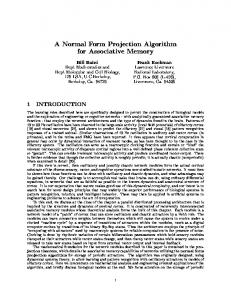
RAPID-2, An Object-Oriented Associative Memory Applicable to Genome Data Processing Denis Archambaud, Pascal Faudemay, Alain Greiner {archambaud, faudemay, greiner}@masi.ibp.fr MASI Laboratory - UPMC 4 place Jussieu 75252 Paris Cedex 05, France Abstract We present an on-going research concerning an object oriented associative memory, organized into virtual circuits. It is a massively parallel architecture, fully programmable and configurable, composed of VLSI circuits. It is well adapted to genome data processing. DNA and proteins sequences alignment is a very important application in nowadays research in biology. Standard sequences alignment usually entails software implementation with disastrous execution time (typically one year). A parallel implementation can solve such a problem. Rapid-2 will be able to execute and accelerate genome tasks. We programmed and simulated several variants of the Needleman & Wunsch algorithm with progressive complexity (gaps, Dayhoff mutation matrix). Execution time evaluations of all these methods are presented. We consider that Rapid-2 could improve nowadays software implementation of a factor 100.
1: Introduction
The memory is divided into sets. Registers associated to the same comparator belong to different sets. There is one set active at a time, and thus one register used by the comparator at a time. Hashing is used to determine the active set : data are hashed and stored in a set corresponding to their hash-value, so that retrieval only implies comparisons in one set, performed in parallel. Setassociative memory is used for many specific applications, such as accelerators for electronic dictionaries [Motomura 90]. However, classical set-associative memories only support one type of data and one type of query. Rapid-2 is an object-oriented set-associative memory. The arithmetic and logical unit (ALU) is a complex unit performing high-level operations, thus the memory is also a massively parallel execution unit with parallel access to the data. The memory can be divided into several virtual circuits (containers), so that different data can be stored with different size and storage parameters. Structured data are supported in the memory by the mean of tags - i.e. some extra bits associated to each register, coding the hierarchy and other informations. Rapid-2 will speed-up persistent object-oriented languages (e.g. persistent C++, query languages) and genome applications.
Many data processing applications need intensive calculation. This is the case for knowledge bases, large databases, genomics, image processing and many more topics. To increase the calculus power, we can either improve the performances of processors themselves - but this implies to build a new computer and all its relevant architecture - or design a system that could be connected to a computer and would speed-up its operations. The advantages of the second solution is its low-price conception and the compatibility with different machines.
Genome research is a major scientific challenge which implies very large amounts of calculation. A current genome application consists in searching a sequence in a database for an approximate match and performing the alignment of proteins or DNA sequences. Nowadays algorithms have a redhibitory execution time with software implementation on workstations (typically one year, [Gonnet 92]).
Associative memories are based on an access to the data depending on their content rather than their address. Parallelism involved in such memories is based on an SIMD organization (Simple Instruction for Multiple Data): each register is associated to a comparator or an arithmetic and logical unit, all the comparators execute the same instruction in parallel. Architectures designed so far with such a concept are dedicated to specific applications as artificial intelligence circuits [Ogura 89].
Parallelism is a solution to speed-up such processing. Use of parallel MIMD machines [Miller 91] implies interprocess communications and means very expensive architectures. Two-dimensionnal parallel architectures as ICL Distributed Array Processor are also used [Coulson 87], but such an organization raises a connection problem that limits the array size (or the processor complexity). Rapid-2 is a one-dimensional SIMD organization which solves some data access problems since memory is distributed with the processors.
Set-associative memories increase the memory ratio vs logic by associating multiple registers to each comparator.
Rapid-2 can be programmed in accordance to the sequence alignment method used in genomics research. We
already simulated some known algorithms, from the mere distance calculation to the Needleman-Wunsch algorithm with Dayhoff mutation matrix utilization [Needleman 70], [Gonnet 92].
•
This paper is organized as follows : we first present the Rapid-2 circuit architecture and functionalities, its logical and physical organization, the main devices connected with this specific architecture, and the instruction set. We then present the implementation of the distance calculation with program listing and time analysis. More specific genome calculation algorithms with progressive complexity are also discussed.
The user accesses a container by indicating the number of its first page. The segment is accessed by a selection upon the segment number. The set is accessed by hashing a key. The peculiar word of a data is accessed by an offset. The address formula for a page access is then : page number =container's first page + set number * block size + offset where the set number is the hash-value, the block size is the number of pages of a set.
2: Circuit organization and functionalities
In order to optimize the access speed, the user indicates directly page = container's first page + offset, the formula is then page number = page+ set number * block size . Block size is always an integer power of 2, from 2 to 32, thus the multiplication is performed by a mere logical shift. Figure 1 shows part of the data hierarchy in some containers.
We present in that chapter the logical organization of the system (regardless the hardware constraints), and the functionalities related to such an architecture.
2.1: Data Hierarchy The memory can be seen as an array in which each column (called a cell) contains 64 words, and each line (called a page) is made up of a word of each cell. Thus, there are 64 pages in the memory, and many cells. The capacity of a N cell memory is 64.N words. The word size is 52 bits : 32 data bits plus 20 tag bits, tags are flags dedicated to a data word, it enables to support the data hierarchy and to record some events on a data.
cell
•
3-block data set segment 1
Data is the atomic object that the user can store in the memory. It is composed of one block in monoblock mode, and of an arbitrary number of blocks in multiblock mode. Set - a set is composed of a number of successive pages. When storing data in the memory, an hashcode is calculated from a key (usually a part of the datum). Data are always stored in the set corresponding to their hashcode (this is the set-associative approach).
page
container 1
The data stored in the memory are structured into a seven-level hierarchy which names are (from top level to the bottom) container, segment, set, data, block, element and word. •
Element is a subdivision of a datum identified by an element-number (coded in the tag). The user defines the element-number of each word and can run selections upon one or several elements.
segment 2
empty pages (unused) Figure 1 : Paginated structure of the Rapid-2 memory
2.2: Supported types •
Container is a virtual circuit in which the user defines the structure (size of a set, number of sets, and consequently number of possible hash values). Completely different data can be stored in Rapid-2 in different containers with different storage format. A container is accessed by its first page number.
•
Segment is a subdivision of a container, identified by a segment-number (coded in the tag). The user can manage segments as sub-containers with the same parameters as the container.
•
Block is a datum or a part of a datum contained in one cell. In monoblock mode, each block is a datum.
The word type is not connected with the data hierarchy (except for texts), it can be different from a word to another in the same block. Rapid-2 can deal with three different data types: •
Integers - 32-bit signed integers are supported, with 1-cycle operations as addition, substraction, shift, comparisons and boolean operations. Multiplication and division are also possible with multiple cycles, using the basic operations add, sub and shift.
•
Bytes - the 32-bit word can be used to store four 8-bit unsigned integers. In such a situation, the arithmetic and logical unit is divided in four 8-bit parallel units
performing the same functionnalities. The parallelism is then multipled by a factor 4. •
Text - the data words are used to store successive bytes of a text. The format is equivalent to the Byte type, however text implies a special storage format in the data structure : a block occupies always 2 pages, and contains 8 characters. In this mode, data, set, and hashing are not available. The text is wrapped, this means that blocks are stored from the left cell to the right; when the last cell on the right is reached, the following blocks are stored on the two pages below. This data type has been implemented to make Rapid-2 able to efficiently store long texts, since this is a very common object in databases.
2.3: Cell Functionalities The cell is the associative unit, it means that the most optimized it will be (concerning size and consumption), the greater will be the number of cells. Therefore, the cell contains neither sequencer nor instruction-decoder or devices that could be shared between cells. The cell basically contains a register file (64 words of 52 bits), auxiliary registers (addressable by the user as auxiliary pages for temporary operations), an arithmetic and logical unit performing integer addition and substraction and standard logical operations, a token unit (cf §2.4), a very simple address driver, and a limits management unit (cf § 2.5). The cells are connected by a monodimentional mesh. We shall consider an horizontal connection in which the "first cell" is on the uttermost left, and the "last cell" is on the uttermost right (cf figure 3). We can therefore define some oriented actions, as shifting operations consisting in transferring a datum from a cell to its right or left neighbor. The cell interface is composed of an address bus (to code the page number), a data bus, and two 52-bit mesh for shifting data, one connected to the previous cell and one connected to the next cell. The token state is also output to the token trees.
2.4: Token unit Each cell has a token which is a 1-bit flag that determines whether the cell is active or not. This device is necessary, due to the SIMD organization of the system : each instruction is sent to all the cells, but executed only in those whose token is set. Therefore, each action in the memory is a succession of cell selections (token affectations) and operation executions. Since the token unit involves important capabilities in such an architecture, it is a complex part of the circuit. The tokens can be affected regarding the result of a comparison on data or tag, so that they can indicate the positions of searched words or the positions related to the structure (i.e. data beginning/end). Token transformations are possible too, such as shift left, shift right, propagation, tokens copying into a tag bit, or tokens
derivation. Some of these transformations are performed by a binary tree connected to all the tokens. It is basically an Anderson tree [Anderson 74] performing arbitration (i.e. find first/last set token). We have modified it so that it performs local propagation (limited to one datum) and can be used to indicate whether all the cells are active or not (or tree).
Update instructions Load: data are stored in the circuit Modify: selected data are replaced in parallel Suppress: selected data are suppressed Insert: data are inserted after its predecessor Copy: data transfer between pages Move-cont.: container transfer Change-limit: loads limits for hashing by intervals Retrieval instructions Select: selects data satisfying some data value Tag-select: selects data satisfying some tag values Read: returns selected data with their tags Redistribution instructions Rehash: calculates a new hashcode for each data Redistrib: redistributes rehashed data between sets Integer arithmetic and binary operations Aggregate: calculates an aggregate on virtual classes Operation: pilots the ALU functionnalities Alter-token: pilots the token unit functionnalities Customized instruction This is an instruction which microprogram is written and loaded by the user. The control-store is a RAM addressable from the host-computer so that any instruction can be microprogrammed from the software layer (cf §3.2). Figure 2 : Instruction set
2.5: Hashing capabilities When storing a datum in the memory, the first word is hashed and not stored (it is the key), the resulting hashcode determines the destination set. Hashing is carried out by hardware and can be parameterized by the user. The hashcode size can be defined from 1 bit (2 sets) to 5 bits (32 sets). Two hash types are available: folding and intervals. Folding is a xor function of different bits of the key which returns an integer. Four variants of the function can be used, depending on the distribution of the hot bits (i.e. the bits which probability to be different from one key to another is the highest). This ensures the best hashcodes distribution and therefore the highest set filling efficiency. When hashing by intervals, the key range is divided into intervals, thus the hashcode is the number of the interval which includes the key. Each cell can store one
interval limit (and the corresponding hashcode), so that the key is compared in parallel with all the limits. The first successful comparison on the left is then selected and the corresponding hash-code is yielded. Several limit sets can be stored in the Rapid-2 system, the user can therefore define different hashing functions adapted to the data specificities.
control circuit. This chapter describes this organization. Figure 3 shows the architecture. Basically, it is composed of numerous identical cells connected to an arbitration tree and a sequencer. Parts of the arbitration tree are implemented in the memory circuit to reduce the interface sizes, the tree is completed in the controller.
3.1: Memory circuit 2.6: Instruction set A high-level instruction set makes Rapid-2 easy to interface with a software layer. An instruction is a 32-bit word sent to the circuit and interpreted by an hardware sequencer that generates commands for the cells (microinstruction). Figure 2 presents the instruction set. The Copy instruction is able to transfer a datum from a cell to the next or previous one. This possibility is very important because it enables to program systolic algorithms, usually applied to bidimensional problems. The program presented in chapter 4 uses a systolic method to solve a bidimensional problem.
3: Hardware architecture With nowadays technology, the whole memory cannot be contained in a single circuit. Therefore, the Rapid-2 is a board connecting several memory circuits and one
The memory is composed of several basic components called memory circuit. It contains cells and a local token tree. Each cell reads the same data and address bus. Almost one half of the cell is composed of memory, the rest is used to implement the arithmetic and logical unit, the token unit and the auxiliary registers. Since the cell is the replicated unit which determines the parallelism degree, it must be optimised. Therefore, it contains none of the functionnalities that would be redundant (i.e. which would have an identical behavior in all the cells), and its layout is particularly optimized.
3.2: Control circuit An arbitration tree is necessary to interconnect the local trees of each circuit. The sequencer provides a microinstruction sent to all the cells. The sequencer is composed of a RAM control-store. The host-computer can access some registers in the controller to send data and
52 mesh
memory circuit cell cell
memory circuit
cell
cell cell
cell
...
...
arb. tree
memory circuit cell cell
....
arb. tree
arb. tree databus + addrbus
arb. tree
Controller µinstr bus
sequencer
42
52 + 3 host data bus
32
32
cell ...
host address bus
Board Interface Figure 3 : board architecture
instructions by simply addressing it as part of its memory. The control-store can also be addressed so that the user can define his own instructions.
incremented since G≠C, hence 1. After computation, the last line contains the distances. In figure 4, the 0 value in the last line indicates a perfect match in the text (null distance).
3.3: Feasibility We aim at a 16 memory circuit board, with 16 cells in each one, i.e. 256 cell memory. Such an expectation is based on different circuits implemented in the MASI laboratory, and particularly a DLXm implementation using a 32-bit DataPath and a Mealy automaton [Patterson 89]. We estimate that each circuit will contain about 1,000,000 transistors and will be a 1 cm size square. The memory circuit and the controller will have approximately the same sizes, the memory being core-limited and the controller being pad-limited. The Rapid-2 board will then feature a 64 Kilo-bytes memory (not counting tag) and will be designed to support a 30 MHz clock rate. The Alliance CAD tool developed at the MASI laboratory will be used for logical simulation (VHDL), layout generation, and behavioral verification [Greiner 92].
4: A fundamental operation in genomics: approximate searching Genome sequence processing involves an important amount of data, and therefore a complex processing whose execution time is usually redhibitory in traditional software implementation. As genome projects around the world produce data at a growing rate, genomics processing could become the bottleneck of these initiatives. Hardware accelerators is a solution to this problem. In this chapter, we describe an algorithm that performs an approximate matching between a pattern and a stored text. A sequence can be coded as a text, each character coding an amino acid, or base pair.
4.1: Distance calculation - general method Approximate searching consists in calculating - for each text character - a distance between a pattern and the text. This distance represents the minimum number of characters to insert or delete or change in the pattern to make it match with the relevant part of the text. Distances are calculated using a matrix whose columns are connected to the text characters and lines to the pattern characters. The matrix values are calculated from the first line to the last, from the left column to the right one. Each value is equal to the minimum of the three closer values upward, backward and diagonally. Furthermore, this value is incremented if the pattern character connected with the current line is different from the text character connected with the current column (penalty). Figure 4 is an example of the matrix calculation. For instance, the matrix element corresponding to the letter 'G' in the pattern and the letter 'C' in the text has the value 1 because values upward, backward and diagonally are respectively 0, 2 and 1. The result is the minimum (i.e. 0)
Initial conditions : when computing on the first matrix line, values upward and diagonally are zero. When computing on the first matrix column, value backward is maximum word value. A A A T C G A T T G A A A 0 0 0 1 1 1 0 1 1 1 0 0 T 1 1 1 0 1 2 1 0 0 1 1 1 C 2 2 2 1 0 1 2 1 1 1 2 2 G 3 3 3 2 1 0 1 2 2 1 2 3
Figure 4 : Distance calculation between text AAATCGATTGAA and pattern ATCG
4.2 : Adaptation to the Rapid-2 architecture The parallel architecture is well adapted to a systolic implementation. The pattern characters are successively aligned to each text character by shifting them to the right (figure 5), each alignment state is called a step. At each pattern character we associate several values : the pattern character itself (P), values upward (U), backward (B), diagonally (D), and the result (R).
A A T C G
A A T C G A T T G A A A T A C T A G C T A G C T A G C T A ...
Figure 5 : Pattern shifting for the systolic algorithm At each step, value R is calculated in parallel in each pattern character with formula R = min ( U, B, D ). R is incremented when the pattern character is different from the corresponding text character. Figure 6 describes the value transfers during a systolic step. Here are the details concerning pattern character 'G' on the the text character 'C' (situation of figure 4) :
α The Backward value is the Result of pattern character 'G' aligned with text character 'T' at time t-1 (i.e. 2, see figure 4) β The Upward value is the Result of character 'C' aligned with text character 'C' at time t-1 (i.e. 0) γ The Diagonal value is the Result of character 'C' aligned with text character 'T' at time t-2 (i.e. 1, see figure 4); but this R value has been transferred in B value of character 'C' while previous shift (γ ' on figure 6), therefore D value is B value of character 'C' aligned with text character 'C' at time t-1
T(ext) P(attern) B(ackward) D(iagonal) R(esult)
The value R in character 'G' at time t is then : R = min ( B, U, D ) +1 as 'G'≠'C' T
Cell Figure 7 : Pages organization for distance calculation
C
text B
C
t-2
Figures 6 and 7 clearly show that page D is not concerned by shiftings, it only stores a value for the minimum calculation. Therefore, this page is a temporary page coded in auxiliary registers. Thus only 4 memory pages are necessary to run the algorithm.
B
U
U
D
D
R
R
T
γ' t-1
G
B U
B U
D
D
β
R
α t
4.4: Systolic step programming
C
R B U D
Figure 8 lists the Rapid-2 instructions to run one step. We used a pseudo-language to make the program easier to understand. This algorithm has been simulated by software.
γ
G
R
time
Figure 6 : Values transfers concerning character G
4.3: Implementation in Rapid-2 data structure We use 5 pages in the circuit : the first page stores the text (page T), other pages store values P, B, D and R. The systolic step is detailed in figure 7 : • page P is shifted to the right • page B is copied to page D (corresponding to γ in fig 6) • page R is right shifted and copied to page B (corresponding to α in figure 6) • minimum of values in D, R, B is copied to page R • values R are incremented where P≠T The b transfer (figure 6) is not necessary because page U is replaced by page R so that formula R = min ( B, U, D) + 1 is transformed into R = min (B, R, D) + 1
// B is transferred to D (γ transfer in fig 6) ALTER-TOKEN (op=set) COPY (src=page B; tgt=page D; shift=0) // R is shifted and transferred to B // (α transfer in figure 8) OPERATION (src=page R ; tgt=page B ; op=rr8) COPY (src=page B ; tgt=page B ; shift=right) // P is right shifted ALTER-TOKEN (op=set) OPERATION (src=page P ; tgt=page P ; op=rr8) COPY (src=page P ; tgt=page P ; shift=right) // minimum calculation ALTER-TOKEN (op=copy flag to token;page=page P) OPERATION (src1=page B ; src2=page R ; op='