RAZOR: CIRCUIT-LEVEL CORRECTION OF TIMING ERRORS FOR LOW-POWER OPERATION DYNAMIC VOLTAGE SCALING IS ONE OF THE MORE EFFECTIVE AND WIDELY USED METHODS FOR POWER-AWARE COMPUTING. HERE IS A DVS APPROACH THAT USES DYNAMIC DETECTION AND CORRECTION OF CIRCUIT TIMING ERRORS TO TUNE PROCESSOR SUPPLY VOLTAGE AND ELIMINATE THE NEED FOR VOLTAGE MARGINS.
Dan Ernst Shidhartha Das Seokwoo Lee David Blaauw Todd Austin Trevor Mudge University of Michigan Nam Sung Kim Intel Krisztián Flautner ARM Ltd.
10
A critical concern for embedded systems is the need to deliver high levels of performance with ever-diminishing power budgets. This is evident in the evolution of mobile phones: in the past seven years, mobile phones have shown a 50× improvement in talk-time per gram of battery (based on a comparison of standard configurations of Nokia 232 and Ericsson T68 phones). At the same time, mobile phones have been taking on computational tasks typically performed on desktop computers: 3D graphics, video display, Internet access, and gaming. As the breadth of applications for these devices widens, a single operating point no longer suffices to efficiently meet their processing and power consumption requirements. For example, MPEG video playback requires an orderof-magnitude higher performance than playing MP3s. However, running at the performance level necessary for video is not energy efficient for audio. These mobile devices can bridge the gap between high performance and low power through dynamic voltage scaling (DVS).1 Lowering clock frequency to the minimum
required level exploits periods of low processor utilization and allows a corresponding reduction in supply voltage. Because dynamic energy scales quadratically with supply voltage, DVS can significantly reduce energy use.2 Enabling systems to run at multiple frequency and voltage levels is challenging and requires characterizing the processor to ensure correct operation at the required operating points. We call the minimum supply voltage that produces correct operation the critical supply voltage. This voltage must be sufficient to ensure correct operation in the face of numerous environmental and process-related variabilities that can affect circuit performance. These include unexpected voltage drops in the power supply network, temperature fluctuations, gate length and doping concentration variations, and cross-coupling noise. These variabilities can be data dependent, meaning that they exhibit their worst-case impact on circuit performance only under certain instruction and data sequences and that they comprise both local and global components. For instance, local process variations will affect specific regions of the die in different and
Published by the IEEE Computer Society
0272-1732/04/$20.00 2004 IEEE
independent ways, while global process variations affect the entire die’s circuit performance and create variation from one die to the next. Similarly, temperature and supply drop have local and global components, while cross-coupling noise is a predominantly local effect. To ensure correct operation under all possible variations, designers typically use corner analysis to select a conservative supply voltage. This means adding margins to the critical voltage to account for uncertainty in the circuit models and for the worst-case combination of variabilities. However, such a combination of variabilities might be very rare or even impossible in a particular chip, making this approach overly conservative. And, with process scaling, environmental and process variabilities will likely increase, worsening the required voltage margins. To support more-aggressive power reduction, designers can use embedded inverter delay chains3 to tune the supply voltage to an individual processor chip. The inverter chain’s delay serves to predict the circuit’s critical-path delay, and a voltage controller tunes the supply voltage during processor operation to meet a predetermined delay through the inverter chain. This approach to DVS has the advantage that it dynamically adjusts the operating voltage to account for global variations in supply voltage drop, temperature fluctuation, and process variations. However, it cannot account for local variations, such as local supply-voltage drops, intradie process variations, and cross-coupled noise. Therefore, the approach requires adding safety margins to the critical voltage. Also, an inverter chain’s delay doesn’t scale with voltage and temperature in the same way as the criticalpath delays of the actual design. The latter delays can contain complex gates and pass-transistor logic, again requiring extra voltage safety margins. In future technologies, the local component of environmental and process variation is likely to become more prominent, and, as Gonzalez et al. noted, the sensitivity of circuit performance to these variations is higher at lower operating voltages, thereby increasing the necessary margins and reducing the scope for energy savings.4
Razor approach Razor, a new approach to DVS, is based on dynamic detection and correction of speed-
path failures in digital designs. Its key idea is to tune the supply voltage by monitoring the error rate during operation. Because this error detection provides in-place monitoring of the actual circuit delay, it accounts for both global and local delay variations and doesn’t suffer from voltage scaling disparities. It therefore eliminates the need for voltage margins to ensure always-correct circuit operation in traditional designs. In addition, a key Razor feature is that operation at subcritical supply voltages doesn’t constitute a catastrophic failure but instead represents a trade-off between the power penalty incurred from error correction and the additional power savings obtained from operating at a lower supply voltage. The Razor project includes four faculty members and more than 10 graduate students in the Electrical Engineering and Computer Science Department at the University of Michigan. We implemented the Razor technique in a prototype 64-bit Alpha processor design and used it to obtain a realistic measure of the power savings and overhead for inplace error detection and correction. We also studied the error rate trends for data path components, using both circuit-level simulation and silicon measurements of a fullcustom multiplier block. Architectural simulations then helped us analyze the overall throughput and power characteristics of Razor-based DVS for different benchmark test programs. On average, Razor reduced simulated consumption by more than 40 percent, compared with traditional design-time DVS and delay-chain-based approaches.
Razor error detection and correction Razor relies on a combination of architectural and circuit-level techniques for efficient error detection and correction of delay path failures. Figure 1 illustrates the concept for a pipeline stage. A so-called shadow latch, controlled by a delayed clock, augments each flipflop in the design. In a given clock cycle, if the combinational logic, stage L1, meets the setup time for the main flip-flop for the clock’s rising edge, then both the main flip-flop and the shadow latch will latch the correct data. In this case, the error signal at the XOR gate’s output remains low, leaving the pipeline’s operation unaltered. If combinational logic L1 doesn’t complete its computation in time, the main
NOVEMBER–DECEMBER 2004
11
MICRO TOP PICKS
clk
Logic stage L1
D1
0 1
Main flip-flop
Logic stage L2
Q1 Error_L
Shadow latch Comparator Error
Razor flip-flop
clk_delay
Figure 1. Pipeline stage augmented with Razor latches and control lines.
flip-flop will latch an incorrect value, while the shadow latch will latch the late-arriving correct value. The error signal would then go high, prompting restoration of the correct value from the shadow latch into the main flip-flop, and the correct value becomes available to stage L2. To guarantee that the shadow latch will always latch the input data correctly, designers constrain the allowable operating voltage so that under worst-case conditions the logic delay doesn’t exceed the shadow latch’s setup time. If an error occurs in stage L1 during a particular clock cycle, the data in L2 during the following clock cycle is incorrect and must be flushed from the pipeline. However, because the shadow latch contains the correct output data from stage L1, the instruction needn’t reexecute through this failing stage. Thus, a key Razor feature is that if an instruction fails in a particular pipeline stage, it reexecutes through the following pipeline stage while incurring a one-cycle penalty. The proposed approach therefore guarantees a failing instruction’s forward progress, which is essential to avoid perpetual failure of an instruction at a particular pipeline stage. We limit this article to Razor’s use on combinational logic blocks contained within the pipeline data paths. Therefore, we apply Razor to a simple embedded processor that uses an in-order pipeline with simple control and small caches. In such a processor, control logic and SRAM structures remain error free, even at the
12
IEEE MICRO
worst-case frequency and voltage. Therefore, they don’t require Razor technology.
Circuit-level implementation issues Razor-based DVS requires that the error detection and correction circuitry’s delay and power overhead remain minimal during errorfree operation. Otherwise, this circuitry’s power overhead would cancel out the power savings from more-aggressive voltage scaling. In addition, it’s necessary to minimize error correction overhead to enable efficient operation at moderate error rates. We applied several methods to reduce the Razor flip-flop’s power and delay overhead, as shown in Figure 2. The multiplexer at the Razor flip-flop’s input causes a significant delay and power overhead; therefore, we moved it to the feedback path of the main flipflop’s master latch, as Figure 2 shows. Hence, the Razor flip-flop introduces only a slight increase in the critical path’s capacitive loading and has minimal impact on the design’s performance and power. In most cycles, a flip-flop’s input will not transition, and the circuit will incur only the power overhead from switching the delayed clock, thereby reducing Razor’s power overhead. Generating the delayed clock locally reduces its routing capacitance, which further minimizes additional clock power. Simply inverting the main clock will result in a clock delayed by half the clock cycle. Also, many noncritical flip-flops in the design don’t need Razor. If the maximum
clk D
clk_b
clk_b Q
clk
Metastability detector Inv_n
Error_L
Inv_p
clk_del_b
Error_L
clk_del Shadow latch
Figure 2. Reduced-overhead Razor flip-flop and metastability detection circuits.
delay at a flip-flop’s input is guaranteed to meet the required cycle time under the worst-case subcritical voltage, the flip-flop cannot fail and doesn’t need replacement with a Razor flip-flop. We found that in the prototype Alpha processor, only 192 flip-flops out of 2,408 required Razor, which significantly reduced the Razor approach’s power overhead. For this prototype processor, the total simulated power overhead in error-free operation (owing to Razor flipflops) was less than 1 percent, while the delay overhead was negligible. Using a delayed clock at the shadow latch raises the possibility that a short path in the combinational logic will corrupt the data in the shadow latch. To prevent corruption of the shadow latch data by the next cycle’s data, designers add a minimum-path-length constraint at each Razor flip-flop’s input. These minimum-path constraints result in the addition of buffers during logic synthesis to slow down fast paths; therefore, they introduce a certain power overhead. The minimum-path constraint is equal to clock delay tdelay plus the shadow latch’s hold time, thold. A large clock delay increases the severity of the short-path constraint and therefore increases the power overhead resulting from the need for additional buffers. On the other hand, a small clock delay reduces the margin between the main flip-flop and the shadow latch, hence reducing the amount by which designers can drop the supply voltage below the critical supply voltage. In the prototype 64-bit Alpha design, the clock delay was half the clock period. This simpli-
fied generation of the delayed clock while continuing to meet the short-path constraints, resulting in a simulated power overhead (because of buffers) of less than 3 percent.
Pipeline error recovery mechanisms It is imperative that errant pipeline results not be written to the architected state before Razor has validated them. Because validating timingspeculative values takes two additional cycles (one for error detection and one for metastability detection), there must be two nonspeculative stages between the last Razor latch and the writeback stage. In our design, memory accesses to the data cache are nonspeculative; hence, the design requires only one additional pipeline stage—called stabilize—before writeback. The stabilize stage introduces an additional level of register bypass. Because store instructions must execute nonspeculatively, they execute in the pipeline’s writeback stage. The pipeline error recovery mechanism must guarantee that in the presence of Razordetected errors, an incorrect value does not corrupt register or memory state. In the following three subsections, we highlight three possible approaches to implementing pipeline error recovery. The first is a simple but slow method based on clock gating; the other two methods are much more scalable techniques based on pipelining.
Clock gating The simplest approach to pipeline error recovery is based on global clock gating. If
NOVEMBER–DECEMBER 2004
13
MICRO TOP PICKS
Razor detects an error in any stage, the entire pipeline stalls for one cycle by gating the next global clock edge. The additional clock period lets every stage recompute its result using the Razor shadow latch as input. Consequently, the correct value from the Razor shadow latch will replace any previously forwarded errant values. Because all stages reevaluate their result with the Razor shadow latch input, a single cycle can tolerate any number of errors, guaranteeing forward progress. If all stages produce an error in each cycle, the pipeline will continue to run, but at half the normal speed.
Counterflow pipelining In aggressively clocked designs, it might not be possible to implement global clock gating without significantly affecting processor cycle time. Consequently, we have designed and implemented a fully pipelined error recovery mechanism based on counterflow pipelining techniques.5 This approach places negligible timing constraints on the baseline pipeline design at the expense of extending pipeline recovery over a few cycles. Razor’s detection of errors requires two specific actions. First, the stage computations following the failing Razor latch must be nullified. This action relies on a bubble signal, which indicates to the next and subsequent stages that the pipeline slot is empty. Second, asserting the stage ID of the failing stage triggers the flush train. In the following cycle, the Razor shadow latch injects the correct value back into the pipeline, letting the errant instruction continue with its correct inputs. Additionally, the flush train begins propagating the failing stage’s ID in the opposite direction of the instruction’s movement. At each stage visited by the active flush train, the corresponding pipeline stage result is invalidated along with the one immediately preceding it. (The flush train must nullify two stages to account for the twice-relative-pace of the main pipeline.) When the flush ID reaches the start of the pipeline, the flush control logic restarts the pipeline at the instruction following the errant instruction. If multiple stages experience errors in the same cycle, each of those stages will initiate recovery, but only the error Razor detects closest to writeback will complete. Later recoveries will flush earlier ones.
14
IEEE MICRO
Micro-rollback The counterflow pipelining approach mitigates the circuit complexity problems with the recovery signal, but it also costs many more cycles in recovery time because of the need to flush instructions and reexecute them, even though their data might be correct. Tamir et al. discussed micro-rollback as a method for quickly recovering from transient faults that occurred during execution.6 We examined this design and saw that the concepts would easily apply to stall logic. Micro-rollback keeps a first-in first-out queue of length N backing each register in the pipeline. Each cycle, the design saves the value in the pipeline register to the backing storage. When a stall signal arrives, the backing storage can reinject the old value for the stage register into the pipeline, simulating a stall without restricting the stall signal’s arrival to a very small clock window. On a stall, the signal can have up to N cycles to propagate to all the necessary stages. Although micro-rollback reduces the number of penalty cycles an error incurs, it requires adding register components to the pipeline, and this raises flip-flop energy consumption approximately 15 percent per rollback entry for each register that requires backup.
Failure not an option A key requirement of pipeline recovery control for any of the three schemes described is that it not fail under even the worst operating conditions (for example, low voltage, high temperature, and high process variation). A conservative design approach that validates the timing of the error recovery circuits at the worst-case subcritical voltage lets us meet this requirement.
Supply voltage control Many of the parameters affecting the necessary voltage margin vary over time. Temperature margins will track ambient temperatures, and processing demands can cause these margins to vary across a die. Consequently, to optimize energy conservation, it’s desirable to introduce a voltage control system into the design. For Razor, the voltage control system adjusts the supply voltage on the basis of monitored error rates. A very low error rate could indicate that circuit computation is finishing too quickly and voltage should be lower.
10.0000000 1.0000000
30 percent energy savings
0.1000000 0.0100000
22 percent savings
0.0010000 0.0001000 0.0000100 One error approximately every 20 seconds
Random
0.0000010 0.0000001
Error rate percentage (log scale)
100.0000000 35 percent energy savings with 1.3 percent error
0.0000000 1.78 1.74 1.70 1.66 1.62 1.58 1.54 1.50 1.46 1.42 1.38 1.34 1.30 1.26 1.22 1.18 1.14 Supply voltage (V) Environmental margin Safety margin Zero margin @ 1.69 V @ 1.63 V @ 1.54 V
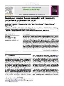
Figure 3. Measured error rates for an 18 × 18-bit field-programmable gate array multiplier block at 90 MHz and 27° C.
Similarly, a low error rate could indicate changes in the ambient environment (say, decreasing temperature), providing an additional opportunity to lower voltage. Increasing error rates, on the other hand, indicate that circuits are not meeting clock-period constraints and voltage should be increased. The optimal error rate depends on several factors, including the energy cost of error recovery and overall performance requirements, but in general it is a small nonzero error rate. As a starting point, we have implemented a proportional control system that adjusts supply voltage in proportion to a sampled processor error rate. To prevent the control system from overreacting and potentially placing the system in an unstable state, the error sample rate is roughly equivalent to the minimum period of the voltage step. Although control of this system might seem simple, our studies show that there is little to gain from morecomplex control systems, such as PID (proportional integral derivative) controllers. Our previous work proposed two other methods for further reclaiming energy from margins:7 • Local DVS. If each pipeline stage has a separate voltage supply, the individual stages tune their own voltage levels. This prevents the problem of a single stage’s limit-
ing the energy savings of other stages that could use lower voltages. However, fitting several independent voltage sources onto a chip is a very difficult (and expensive) packaging issue that designers would need to address to implement this method. • Dynamic retiming. When the number of errors in a pipeline is unbalanced between different pipeline stages, higherror stages can borrow time from lowerror stages using per-stage clock-delay buffers, allowing the global voltage to be lowered further than in the baseline global DVS case. This scheme requires only a single voltage source but still lets stages balance their error rates somewhat to reduce the total energy needed.
Error rate analysis Razor lets a microprocessor tolerate circuit timing errors, thereby permitting operation at a lower voltage, at the expense of decreased instruction throughput. As an initial step in gauging Razor technology’s benefits, we empirically examined the error rate of fabricated logic—an 18 × 18-bit full-custom multiplier block contained within a high-density fieldprogrammable gate array. The Xilinx static timing analyzer indicated that we could clock the circuit at up to 88.6 MHz at 1.5 V and 27°C. Figure 3 illustrates the relationship between
NOVEMBER–DECEMBER 2004
15
MICRO TOP PICKS
voltage and error rates for the multiplier block running with random input vectors at 90 MHz and 27°C. The error rates appear as a percentage on a log scale. The graph also shows three additional design points, gauged using the Xilinx static timing analyzer. The zeromargin point is the lowest voltage at which the circuit operates error free at 27°C. The safetymargin point is the voltage at which the circuit runs without errors at 27°C in 90 percent of the baseline clock period (10 ns at 100 MHz). We would expect this to be approximately the voltage margin required for delaychain tuning approaches, in which voltage margins are necessary to accommodate intradie process and temperature variations. Finally, the environmental-margin point is the minimum voltage required to run without errors at 90 percent of the baseline clock period at the worst-case operating temperature of 85°C. The multiplier circuit fails quite gracefully, taking nearly 200 mV to go from the point of the first error (1.54 V) to an error rate of 5 percent (1.34 V). Strikingly, at 1.52 V the error rate is approximately one error every 20 seconds—or stated another way, one error per 1.8 billion multiply operations. The gradual error rate rise is due to the dependence between circuit inputs and evaluation latency. Initially, only changes in circuit inputs that require a complete re-evaluation of the critical path result in a timing error. As the voltage continues to drop, more and more internal multiplier circuit paths cannot complete within the clock cycle, and the error rate increases. Eventually, voltage drops to the point where none of the circuit paths can complete in the clock period, and the error rate reaches 100 percent. Clearly, if the pipeline can tolerate a small rate of multiplier errors, it can operate with a much lower supply voltage. For instance, at 1.36 V the multiplier would complete 98.7 percent of all operations without error, for a total energy savings (excluding error recovery) of 22 percent over the zeromargin point, 30 percent over the safetymargin point, and 35 percent over the environmental-margin point.
Razor pipeline implementation We implemented the proposed Razor error detection and correction approach in a 64-bit, single-issue, in-order processor using the
16
IEEE MICRO
Alpha instruction set. The memory system consisted of 8 Kbytes each in the instruction and data caches. We implemented the processor in Taiwan Semiconductor Manufacturing Corp.’s 0.18-µm process at 120 MHz. After careful performance analysis, we found that only the instruction decode and execute stages would fail at the worst-case voltage and frequency settings; hence, only these stages required Razor flip-flops for their critical paths. Of 2,408 flip-flops in the design, 192 needed Razor flip-flops. We delayed the clock for the Razor flip-flops by half the clock cycle from the system clock. We submitted the test chip design to MOSIS for fabrication. A layout picture appears in Figure 4, and Table 1 shows some of its specifications. Power analysis of the processor design used both gate-level power simulations and Spice to evaluate the overhead of the error correction and detection circuits. From these simulations, we expect the total power overhead of the Razor error detection and correction circuitry in error-free operation to be 3.1 percent of the total power. A detailed evaluation of our Razor optimization requires intimate knowledge of circuit evaluation characteristics, because Razor timing errors are a direct function of circuit evaluation latency. Typical architectural-based simulation methodologies don’t have this level of detail. At most, architectural simulators will vary the number of cycles an operation executes, on the basis of some model of its circuit complexity—for example, cache latency versus size. To support detailed evaluation of a Razor pipeline with various types of voltage control, we embedded a circuit simulator into our architectural simulator. Our architectural simulator is based on the SimpleScalar toolset.8 The embedded circuit simulator references a combinational logic description of each relevant Razor chip component and interfaces with the architectural simulator on a stage-by-stage basis. A detailed description of our circuit-aware architectural simulation methodology is available in the literature.9 Our evaluation analyzed eight SPEC2000 benchmarks. For each program, we simulated 10 million instruction samples selected using the SimPoint tool’s “early multiple SimPoint” option.10 Figure 5 shows the error rates and energy
3 mm
Table 1. Test chip features and specifications.
I-cache
Regiser file
IF ID
EX
MEM
WB
3.3 mm
D-cache
Feature Technology node DVS supply voltage range Total number of logic gates Die size Clock frequency Clock delay Icache size Dcache size Total number of flip-flops Total number of razor flip-flops Number of delay buffers added Error free operation (simulated) Total power Standard FF energy (static/sswitching) Razor FF energy (static/switching) Total delay buffer power overhead Percent total chip power overhead Error correction and recovery overhead Energy per Razor FF error event Total energy per error event Razor FF recovery overhead at 10 percent error rate
Specification 0.18µm 1.2-1.8V 45,661 3.0 x 3.3 mm 200 MHz 2.5 ns 8 KB 8 KB 2,408 192 2,498 425 mW 49 fJ/95 fJ 60 fJ/160 fJ 12.2 mW 3.1 210 fJ 189 pJ 1 percent
Figure 4. Razor prototype.
1
0.001
1.4
1.42
1.44
1.5
1.48 1.46
1.52
1.56 1.54
1.6
1.58
1.62
1.66 1.64
1.68
1.7
1.74 1.72
1.76
1.8
1.78
0.01
Error rate
0.1
Relative energy
gains versus supply voltage for 1.1 a Razor design reported by Energy our simulator. We normalize Error rate 1 energy at a particular voltage with respect to the enery at ErecoveryoutweighsEcomputesavings as error rate becomes large 1.8 V. We verified correct 0.9 program execution for all plotted points. Because of the 0.8 error correction overhead, Ecomputereduced as energy consumption increasvoltage is lowered 0.7 es at high error rates. Our simulations show that a Razor design reduces the energy to 0.6 Optimal operating compute by 25 to 35 percent, point depending on the program 0.5 being executed. Qualitatively, the labels in Voltage Figure 5 show the relationship between supply voltage, computational energy, and Figure 5. Energy savings over point of first error, as measured from a prototype chip. pipeline throughput. The total energy the pipeline consumes (Epipe) is the sum of the energy used to recover the pipeline from errors (Erecovery). A compute (Ecompute) plus the energy expended to trade-off exists between the pipeline energy
0.0001
NOVEMBER–DECEMBER 2004
17
MICRO TOP PICKS
DVS outperforms all other techniques. We can expect 50 this because this ideal 45 approach to local voltage tun40 ing permits all stages to minimize their energy 35 requirements. Overall, it 30 achieves nearly twice the ener25 gy savings of the Razor global 20 DVS, and it finds a 38 percent 15 total reduction in energy, 10 compared with fully margin5 ed DVS. Global DVS with 0 bzip crafty gcc gzip swim twolf vortex vpr average retiming shows good gains as Benchmark well. This approach achieved a 28 percent energy savings Figure 6. Energy savings over baseline for various Razor-enabled DVS approaches, by over the baseline, and it rendered a 12 percent improveSPEC2000 benchmark. ment in energy savings, compared with original Razor and the recovery energy. With lower voltage, it global DVS. The reduced design cost of takes less energy to perform computation in dynamic retiming, compared with local DVS, the pipeline. However, this also increases the comes at a reduction in energy savings. frequency of errors in the pipeline, which increases the amount of energy expended on azor’s success provides a great opportunirecovery events. The optimal operating point ty to reconsider system design. In particfor the processor is the point at which any fur- ular, the design of functional units and memory ther decrease in voltage would cause the structures could now be optimized for typicalprocessor to expend more energy in recovery case latency instead of worst case. Such new than it would save from the scaling. designs should have lower error rates, thereby creating an additional opportunity to further Voltage control evaluation lower energy demands. MICRO Statically reducing voltage to the energyoptimal fixed voltage point will certainly Acknowledgments improve the energy characteristics of a system We extend thanks to the numerous addithat employs Razor. Here, we consider the tional contributors to the Razor project, potential value of dynamically adjusting sup- including Toan Pham, Sanjay Pant, Rajeev ply voltage to workload characteristics. Rao, Conrad Ziesler, Dave Roberts, and ValeWe simulated the three design variants dis- ria Bertacco. cussed earlier: original global DVS, local DVS, and global DVS with retiming. For each References design, we measured the energy savings over 1. T. Pering, T. Burd, and R. Brodersen, “The the baseline and the performance impact Simulation and Evaluation of Dynamic Voltresulting from Razor timing-error recovery. age Scaling Algorithms,” Proc. Int’l Symp. The baseline pipeline design is the Razor proLow Power Electronics and Design (ISLPED totype design without Razor support (that is, 98), ACM Press, 1998, pp. 76-81. fully margined DVS) running with a fixed 2. T. Mudge, “Power: A First-Class Architecsupply voltage of 1.8 V. All energy measuretural Design Constraint,” Computer, vol. 34, ments are based on circuit-level analyses, no. 4, Apr. 2001, pp. 52-58. which include the cost of Razor error recovery 3. S. Dhar, D. Maksimovic, and B. Kranzen, and clock-delay elements. “Closed-Loop Adaptive Voltage Scaling ConFigure 6 shows the relative energy savings troller for Standard-Cell ASICs,” Proc. Int’l for the simulated benchmarks. Clearly, local Symp. Low Power Electronics and Design Global DVS with retiming
Local DVS
Energy savings (percentage)
Global DVS
R
18
IEEE MICRO
(ISLPED 02), IEEE Press, 2002, pp. 103-107. 4. R. Gonzalez, B. Gordon, and M. Horowitz, “Supply and Threshold Voltage Scaling for Low Power CMOS,” IEEE J. Solid-State Circuits, vol. 32, no. 8, Aug. 1997, pp. 12101216. 5. R. Sproull, I. Sutherland, and C. Molnar, Counterflow Pipeline Processor Architecture, tech. report SMLI-TR-94-25, Sun Microsystems Lab, 1994. 6. Y. Tamir, M. Tremblay, and D.A. Rennels, “The Implementation and Application of Micro Rollback in Fault-Tolerant VLSI Systems,” Digest of Papers, 18th Int’l Symp. Fault-Tolerant Computing (FTCS 88), IEEE CS Press, 1988, pp. 234-239. 7. S. Lee et al., “Reducing Pipeline Energy Demands with Local DVS and Dynamic Retiming,” Proc. Int’l Symp. Low Power Electronics and Design (ISLPED 04), IEEE Press, 2004, pp. 319-324. 8. T. Austin, E. Larson, and D. Ernst, “SimpleScalar: An Infrastructure for Computer System Modeling,” Computer, vol. 35, no. 2, Feb. 2002, pp. 59-67. 9. S. Lee et al., “Advances in Accelerated Simulation: Circuit-Aware Architectural Simulation,” Proc. 41st Design Automation Conf. (DAC 04), ACM Press, 2004, pp. 305-310. 10. T. Sherwood et al., “Automatically Characterizing Large Scale Program Behavior,” Proc. 10th Int’l Conf. Architectural Support for Programming Languages and Operating Systems (ASPLOS 02), ACM Press, 2002, pp. 45-57.
Indian Institute of Technology, Bombay, India. He is a student member of the IEEE. Seokwoo Lee is a PhD student in computer science and engineering at the University of Michigan. His research interests include computer architecture, reliable system design, low-power system design, and computer simulations. Lee has a BS in computer science from the University of Michigan. He is a student member of Gigascale Systems Research Corp. David Blaauw is an associate professor of electrical engineering and computer science at the University of Michigan. His research interests include VLSI design and CAD, with particular emphasis on circuit design and optimization problems for high-performance and low-power designs. Blaauw has a BS in physics and computer science from Duke University, and an MS and a PhD in computer science from the University of Illinois, UrbanaChampaign. He is a member of the IEEE and the ACM. Todd Austin is an associate professor of electrical engineering and computer science at the University of Michigan. His research interests include computer architecture, compilers, computer system verification, and performance analysis tools and techniques. Austin has a PhD in computer science from the University of Wisconsin. Austin is a member of ACM and IEEE.
Dan Ernst is a PhD student in computer science and engineering at the University of Michigan. His research interests include efficient microarchitectures, dynamic instruction scheduling, application-specific processing, and reliable computing. Ernst has a BS in computer engineering from Iowa State University and an MS in computer science and engineering from the University of Michigan.
Trevor Mudge, a faculty member at the University of Michigan, Ann Arbor, is the first Bredt Family Professor of Electrical Engineering and Computer Science. He also directs Idiot Savants, a chip design consultancy. His research interests include computer architecture, CAD, and compilers. Mudge has a PhD in computer science from the University of Illinois, Urbana-Champaign, and is a member of the ACM, the IEE, and the British Computer Society; he is a Fellow of the IEEE.
Shidhartha Das is a graduate student at the University of Michigan, Ann Arbor. His research interests include interconnect analysis and circuit-architectural codesign techniques for low-power digital IC design. Das has a BTech in electrical engineering from the
Nam Sung Kim is Senior Research Scientist with the circuit research laboratory at Intel Corp. His research interests include computer architecture and digital circuit and computer-aided design, with particular emphasis on low-power and process-, temperature-, and
NOVEMBER–DECEMBER 2004
19
MICRO TOP PICKS
voltage-variation-tolerant computer system design. Kim has BS and MS degrees in electrical engineering from the Korea Advanced Institute of Science and Technology, Taejon, Korea, and a PhD in computer science and engineering from the University of Michigan, Ann Arbor. He is a member of the IEEE. Krisztián Flautner is director of advanced research at ARM Limited and the architect of ARM’s Intelligent Energy Management technology. His research interests include highperformance, low-energy processing platforms that support advanced software environments.
10
Flautner has a BS, an MS, and a PhD in computer science and engineering from the University of Michigan. He is a member of the ACM and the IEEE. Direct questions and comments about this article to Dan Ernst, Advanced Computer Architecture Lab, University of Michigan, 1301 Beal Ave., Ann Arbor, MI 48109;
[email protected]. For further information on this or any other computing topic, visit our Digital Library at http://www.computer.org/publications/dlib.
great reasons to renew your IEEE Computer Society membership 1. New for 2004, an online reference book membership benefit – free! 2. Access to any or all of 100 distance-learning courses – free! 3. Personal subscription to Computer magazine – free! 4. Opportunity to subscribe to the complete IEEE Computer Society Digital Library or individual periodicals in your specialty area at the lowest available rates. 5. Advance notice of more than 150 IEEE Computer Society conferences, symposia, and workshops—plus generous discounts on registration fees. 6. Discounts on print books, tutorials, conference proceedings, and extended online reference book collections too! 7. Opportunities to participate in 40+ Technical Committees and over 160 Standards Working Groups. 8. Membership in the nearest of over 150 local chapters worldwide – free! 9. Prestigious email alias of
[email protected] – free! 10. Be part of the profession and a network of over 100,000 of the best and brightest computing professionals around the world.
Do it today!
20
IEEE MICRO
www.ieee.org/renewal