Happy Buddha model, we can quantize dx, dy, and dz to 14 bits. We need 11 bpv ..... [15] R. Southern, S. Perkins, B. Steyn, A. Muller, P. Marais, and. E. Blake.
Receiver-Driven View-Dependent Streaming of Progressive Mesh Wei Cheng
Wei Tsang Ooi
Department of Computer Science, National University of Singapore {chengwe2, ooiwt}@comp.nus.edu.sg
ABSTRACT
Vl
Progressive mesh streaming enables users to view 3D meshes over the network with increasing level of details, by sending coarse version of the meshes initially, followed by a series of refinements. To optimally increase the rendered mesh quality, refinements should be sent in descending order of their visual contributions based on the user’s viewpoint. A common approach is to let the sender decide this sending order, but the computational cost of making this decision prohibits such sender-driven approach from scaling to large number of clients. To improve scalability, we propose a receiver-driven protocol, in which the receiver decides the sending order and explicitly requests the refinements, while the sender simply sends the data requested. The sending order is computed at the receiver by estimating the visibility and visual contributions of the refinements, even before receiving them, with the help of GPU. Experiments show that our protocol reduces the CPU cost of the sender by 24% and the outgoing traffic of the sender by 40%.
Vs
Categories and Subject Descriptors I.3.2a [Graphics Systems]: Distributed/Network Graphics; C.2.4b [Distributed Systems]: Distributed Applications
General Terms Performance, Design
Keywords View-dependent streaming, progressive meshes
1.
INTRODUCTION
High resolution 3D models, such as artworks, cultural heritage, and scientific visualization are increasingly available over the Internet. Stanford Digital Michelangelo Project [11], for example, provides high resolution 3D meshes of statues by Michelangelo. While current generations of commodity GPU already enables realtime rendering of these meshes, transmission of the meshes over the network remains a main bottleneck. For example, the Stanford
Permission to make digital or hard copies of all or part of this work for personal or classroom use is granted without fee provided that copies are not made or distributed for profit or commercial advantage and that copies bear this notice and the full citation on the first page. To copy otherwise, to republish, to post on servers or to redistribute to lists, requires prior specific permission and/or a fee. NOSSDAV ’08 Braunschweig, Germany Copyright 2008 ACM 978-1-60588-157-6/05/2008 ...$5.00.
Vl
vertex split
Vu
Vr
edge collapse
Vt Vr
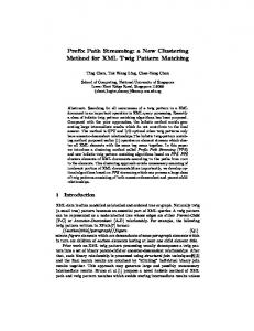
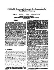
Figure 1: Edge collapse and vertex split. This edge collapse removes one vertex by collapsing the edge Vu Vt to a vertex Vs , and the vertex split reconstructs the edge from Vs . Vertices Vl and Vr are the cut neighbors of Vs .
model of the David statue, with 28 million vertices and 56 million triangles, needs more than 10 minutes to download at 1 Mbps even after compression. A natural choice to reduce the waiting time is progressive streaming, which allows users to see a coarse mesh quickly, with quality improved incrementally as more data arrives. A commonly used representation of 3D models to support progressive streaming is progressive mesh [6], which is based on two operations: edge collapse and vertex split. With the edge collapse operation, we can simplify a complex mesh into a simple base mesh by continuously collapsing one edge into a vertex. We reconstruct the original mesh by applying vertex split, the inverse of the edge collapse, in the reverse order of collapsing (see Figure 1). Therefore, progressive streaming can be implemented by sending the vertex splits as refinements after sending the base mesh. In progressive mesh streaming, it is desirable to increase the visual quality on the client side as quickly as possible. The ideal way is to send the vertex splits in the descending order of their contribution to mesh quality, commonly measured by the Hausdorff distance between the original and reconstructed mesh [5]. As Hausdorff distance is view independent, bandwidth may be wasted in sending invisible vertex splits before the visible ones. Moreover, even among the visible vertex splits, the view-independent metric cannot reflect the real contribution to the visual quality of clients with different viewpoints. A vertex split that significantly changes a mesh may change the rendered image only slightly. A better metric for visual contribution of a vertex split, which considers the receiver’s viewpoint, is an image-based metric similar to that proposed by Lindstrom and Turk [12], using the mean square error between the rendered images of the original mesh and reconstructed mesh. Based on this metric, view-dependent streaming, in which vertex splits are sent in the descending order of their contributions to the quality of rendered image, is introduced. In previous implementations of view dependent streaming [16, 15, 18, 10, 20], the server decides which vertex splits to send. In these implementations, the client sends its viewing parameters to
Sender
Receiver Sender t eques
R
Base M + Inf esh orma tion
(a) common part
Receiver Sender Receiver s r ete param ests Requ View Verte Verte x spli x spli ts ... ts view point s r ete changed param w e i V
(b) sender−driven
(c) receiver−driven
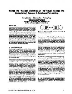
Figure 2: Sender-driven protocol and receiver-driven protocol
the server, and the server sends the chosen vertex splits after determining the visibility and the appropriate resolution of different regions of the mesh (See Figure 2b). This sender-driven protocol, however, has two significant weaknesses. Firstly, it is not scalable to many receivers. Determining visibility of vertices and sorting the visible vertex splits based on their visual contributions are expensive operations. Moreover, the sender needs to maintain the rendering state of each receiver to avoid sending duplicate data when receivers changes viewpoint. Secondly, due to the stateful design and huge computational requirements, the sender-driven approach cannot be extended easily to support caching proxy and peer-to-peer architecture, two common solutions to scalability. It is not realistic to require each proxy or peer to provide much CPU time and memory. Furthermore, a proxy or peer might not store the complete mesh. To address the above weaknesses, we propose a receiver-driven protocol, in which the receiver decides the sending order and explicitly requests the vertex splits. The sender simply sends the data requested (See Figure2c), so no expensive computation is needed. Furthermore, the server is stateless, so existing cache proxy and peer-to-peer techniques can be applied. The receiver-driven protocol also reduces the size of data sent by the sender. In sender-driven protocols, for each vertex split, the sender has to send identifications to indicate which vertex to be split (Vs in Figure 1), requiring at least log2 n bits if n vertices exist [7]. In the receiver-driven protocol, however, the sender needs not send these identifications since the vertex splits can be sent according to the requesting order from the receiver. The identifications, sent by the receiver, consumes the down-link bandwidth of the sender, which is often less likely to be the bottleneck than the up-link. Implementing the receiver-driven protocol is non-trivial. First, we need to assign each vertex a unique identification number so that the receiver can explicitly request vertex splits. Second, the receiver has to efficiently decide the importance of a vertex split based on partially received mesh. Although it is difficult for the receiver to accurately measure the visual importance of a vertex split, we find that estimation suffices in our scheme. The main contributions of our work are as follows. We propose a receiver-driven protocol of view-dependent streaming, which significantly reduces the CPU time of the sender and makes the sender stateless. Our protocol exploits the receiver’s computing resources to approximate the optimal list of vertex splits to receive to improve the rendered mesh quality. We also introduce an algorithm to efficiently encode the receiver’s requests. The rest of the paper is organized as follows. In Section 2, we introduce the related work. We briefly review the traditional viewdependent approaches in Section 3. Then, we present the receiverdriven protocol in Section 4. We evaluate our protocol in Section 5 and conclude in Section 6.
2. RELATED WORK The view-dependent approach first appeared as a dynamic simplification method used for adaptive rendering of a complex 3D mesh [7, 13]. Only vertex splits that contribute to the rendered image will be rendered, allowing real-time rendering of a complex mesh even with limited rendering capability. Besides progressive mesh, other multi-resolution representations, such as vertexclustering and subdivision scheme, are used in view-dependent refinement systems [17, 2, 3]. Later, the view-dependent approach is used in progressive streaming of 3D meshes. In the scheme proposed by Southern et al. [15], the client is stateless and maintains only the visible data. To et al. [16] and Kim et al. [10] proposed that received data are stored in the receiver even after they become invisible, so they need not be resent when they are visible again. In these papers, view-dependent approaches mainly aim at addressing limited rendering capability. Yang et al. [18] and Zheng et al. [20], on the other hand, use view-dependent streaming to address limited network bandwidth. Yang et al. proposed a scheme where the server chooses the appropriate resolution according to the available network bandwidth. Zheng et al. [20] use prediction to reduce the effect of network latency and compensate the round-trip delay with the rendering time. These systems use sender-driven approach and do not address server scalability issues. The main challenge of these view-dependent schemes is finding an appropriate subset of vertex splits to generate a satisfactory rendered image on the client side. The flexibility of choosing a subset of vertices, hence, is crucial in view-dependent streaming. But this flexibility is restricted by the dependency among the vertex splits. For a manifold mesh, a vertex split operation depends on the existence of (a) the vertex to be split (Vs in Figure 1), (b) two cut neighbors (Vl , Vr in Figure 1). More dependencies exist if artificial folds are strictly forbidden [7, 13], but in this paper we ignore these dependencies since we can tolerate temporary folds in our scheme. To et al. [16] further remove the second dependency. In their method, if a cut neighbor does not exist during a vertex split, its ancestor will be used as the cut neighbor instead. Kim and Lee [9] improve this method so that the final mesh can keep the original connectivity. Kim et al. [8] propose a better scheme that enables an ordinary progressive mesh to be split in random order. This method is applied in our protocol to reduce the cut neighbor dependency and will be described in further details in Section 4. The flexibility in choosing split order, however, increases the difficulty in developing an effective encoding scheme. Most compression algorithms for progressive mesh choose a specific order of vertex splits to reduce redundancy by exploring the correlation between consecutive vertex splits. Moreover, compressed data can only be sequentially decoded so we cannot change the sending order. One solution proposed by Yang et al. [18] is to divide the whole mesh into several segments and encode them separately to trade off between flexibility and compression efficiency. The weakness is that the size of the base mesh is relatively large since the original vertices in the border of segments are kept in the base mesh. Furthermore, the quality of the base mesh is uneven. Some related work [8, 19] have proposed compression algorithms that allow random splitting of a mesh without sacrificing compression efficiency. These algorithms are not designed for network transmission, but our scheme extended several ideas from Kim et al. [8] and applied them in view-dependent streaming. The discussion above focuses on view dependent streaming of 3D meshes. View dependent streaming have also been used for other 3D data, such as terrain [4] and 3D scenes [14].
00
01
000
001
010
Base Mesh
10
011
100
ID i ...
101
Vertex Front 0000
0001
0010
00100
0011
00101
0100
0101
Original Mesh
0110
0111 1000 10000
1001 1010
10001
1011 10110 10111
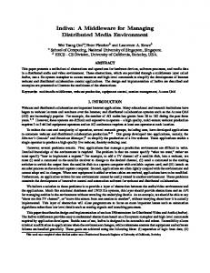
Figure 3: Vertex hierarchy and vertex front. A rectangle represents a vertex and the number inside is its identification number, including tree ID and node ID.
3.
...
CURRENT VIEW-DEPENDENT APPROACHES
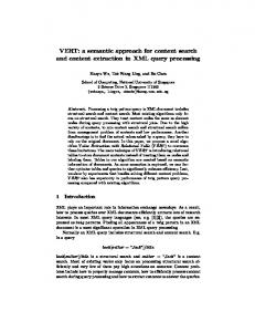
In this section, we briefly review the current view-dependent approaches since they are the basis of our scheme. View-dependent systems often organize the vertices hierarchically. For example, Hoppe [7] represents parent-child relation among the vertices in a progressive mesh as a forest of binary trees, named vertex hierarchy, in which the root nodes are vertices in the base mesh, and the leaf nodes are vertices in the original mesh (see Figure 3). A vertex split replaces one vertex (Vs in Figure 1) by its two children (Vu and Vt in Figure 1). Thus, after applying some vertex splits, the result is a mesh lying between the original mesh and the base mesh. The set of vertices in current mesh is called vertex front [7] (see Figure 3). Due to dependencies among the vertices, visibility determination of a vertex cannot be based on the vertex alone. An invisible vertex still needs to be split if any of its descendants is visible. To avoid determining the visibility recursively for all the descendants, a common method is to use a bounding sphere to represent a vertex and all its descendants. Then, we can safely ignore a vertex split if its bounding sphere falls outside the view frustum. Similarly, a bounding cone of normal is used in back face culling [7]. These bounding object-based methods are not appropriate in our receiver-driven protocol. First, it can only determine the visibility, but cannot sort the vertex splits by their visual contributions. More importantly, the sender has to send these bounding parameters with the vertex splits, almost doubling the data size. We explain our solution to this issue in Section 4. After deciding the visibility, the sender sends the chosen vertex splits to the receiver. Six parameters are needed in a vertex split of a manifold mesh: the identification number (we call ID from now on) of the vertex to be split (Vs in Figure 1) Ids, the IDs for two cut neighbors (Vl and Vr in Figure 1), Idl and Idr , and the coordinates x, y, and z of the right child (Vt in Figure 1). Here, half collapse is used so Vu remains at the same position of Vs . Many implementations use the sequence number of a vertex generated as its ID, but this method enforces the sender to be stateful since the sender has to remember the sending order of each receiver. Kim and Lee [9] proposed a new method, in which every vertex has an ID that is independent of the sending order. The ID of a vertex is a bit string with two parts: tree ID and node ID. Tree ID is the sequence number of the root of this tree in the base mesh, and the node ID represents the path from the root to this vertex in the binary tree. For example, if the tree ID is ‘01’, which is also the ID of the root vertex of this tree, the bit string ‘010’ and ‘011’ are the IDs of the left child and right child of the root vertex respectively. A vertex hierarchy with the assigned IDs is shown in Figure 3. Besides being independent of the sending order, another benefit of this scheme is that the IDs embed the hierarchy. Thus, we can
Data ... E_VS i ...
Sender
E_( ID i ... Decoding ID j ID i
Receiver ID j ...)
ID j E_VS j Searching E_VS ... ... i E_VS ... j E_VS ID n E_VS n i E_VS ... j
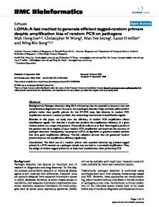
Figure 4: The process of the sender in receiver-driven protocol. E represents encoded data, and VS means vertex split.
deduce the IDs of the ancestors and the descendants of each vertex. For example, given ‘1001’ as the ID of a vertex, we can deduce that ‘100’ is the ID of its parent, ‘10010’ is the ID of its left child and ‘10011’ is the ID of its right child. This property frees the sender from sending the IDs of the two newly generated vertices (Vu and Vt in Figure 1), as they can be deduced by the receiver. The above property is also essential in splitting a progressive mesh in random order, in which the set of neighbors of a vertex during the decoding N ′ may not be N , the set during the encoding. If a cut neighbor with an ID of Id is not in N ′ , then either one of its ancestors or at least one of its descendants must belong to N ′ [8]. In the former case, the ancestor is found and used as the cut neighbor since its ID is the prefix of Id. In the latter case, the descendants of the original cut neighbor in N ′ are found since they all have Id as their prefix. Kim et al. [8] propose a method to find out the proper one as the cut neighbor and they show that despite using replacement in the vertex splitting, the original mesh can be accurately reconstructed when all the vertex splits are applied. Kim et al. [8] also propose an algorithm to encode the IDs of two cut neighbors at about 12 bpv (bit per vertex) and the coordinates x, y, and z at about 21 bpv (with 12 bit quantization). Although their paper focuses on random access of local meshes, we find that this method is useful in progressive streaming as well.
4. RECEIVER-DRIVEN PROTOCOL We now present our proposed receiver-driven protocol for viewdependent progressive mesh streaming. We first introduce the process of transmitting a progressive mesh. Then, we explain how the receiver decides the requesting order. Finally, we explain how we efficiently encode the request from the receiver.
4.1 Mesh Transmission A streaming session is initiated when the receiver requests for a specific mesh. The sender returns the complete base mesh and other necessary information (See Figure 2a) to the receiver. Then, the receiver determines the requesting order of the vertex splits based on the received base mesh, encodes their IDs, and sends them to the sender. On the sender side, the vertex splits are stored in an associative array, which maps the ID to the vertex splits. After receiving the encoded IDs from the receiver, the sender decodes the IDs and searches for the vertex splits in the associative array with IDs as the key values. The matched vertex splits are sent back to the receiver (See Figure 4). The sender does only two things – decode IDs and retrieve the vertex splits, and is therefore stateless.
4.2 Determining Visual Importance We now introduce how the receiver decides the requesting order. We cannot directly use the mean square error between rendered images of reconstructed mesh and original mesh to determine the order, since we need to know the importance of a vertex split before it
1
0
1 01100100 0
v2
0 v1
left subtree
1 1
01 100100 right subtree
1
1 00 1 00 0
0 0
0
left right
Figure 5: Rendered image on the receiver’s screen. The shaded are the screen area of vertex V1 and vertex V2 .
Figure 6: The code of ID of the bottom two vertices is 1011001000.
is received. To overcome this problem, we estimate the importance of the vertex splits to request for based on the received mesh, using the screen-space area of all the neighbor faces of a vertex as the metric of its visual importance (see Figure 5). The rationale is that if the screen area of a vertex (V1 in Figure 5) is larger, it is likely the quality can be improved more by splitting this vertex. Moreover, the screen-space area can be efficiently computed with the help of the GPU, by simply counting the number of pixels inside the faces in the frame buffer. Once the screen-space areas are computed, the receiver sends the requests following the descending order of the screen-space area. If the viewpoint changes, the visual importance will be recomputed and a new list of vertex splits will be requested. Since the received splits refine the mesh, the receiver recomputes the visual importance periodically to update the order even without viewpoint change. The refresh period, one second in our experiments, can be decided by the receiver based on mesh size and network bandwidth. The client can stop requesting once it finds that the rendering quality is sufficient. The receiver has the flexibility of continuing to request for the remaining vertex splits for future use. It can also pre-fetch some invisible vertices based on the prediction of future viewpoints. If the receiver stops requesting when the visual quality is satisfactory, it may miss some visible vertices since the visibility determination is just an estimate. Some invisible vertices may have potentially visible descendants, but they will not be received if their parent has no screen-space area. Fortunately, in most cases, this kind of error is small and tolerable (See the experiment results in Section 5). If strict accuracy is needed, the receiver can choose to continue requesting for the remaining vertex splits.
dx, dy, and dz on average. It is worth noting that more bits are needed for dx, dy, and dz for the earlier vertex splits (about 30 to 35 bpv) since their values are larger. The number of bits needed decreases significantly for later part of the vertex splits as dx, dy, and dz decrease. We think that compressing x, y, and z based on better prediction techniques may further increase the efficiency and it will be an interesting topic of future work. We now introduce how we encode the vertex split IDs, which need 32 bpv without compression. The two parts of an ID, tree ID and node ID, are encoded separately. We use a bit string code to store the encoded result. First, we sort the IDs in a packet according to the tree IDs, in increasing order. Then, we store the first tree ID to code and store each of the following tree ID as the difference from the previous tree ID. Since they are sorted, the differences are positive and relatively small numbers.
4.3 Encoding of Vertex Splits and IDs
Next, we encode the node IDs in a tree into a bit string with a recursive algorithm (See Algorithm 1). In brief, we use two bits to represent whether one or more descendants need to be split (‘1’ for yes and ‘0’ for no) in the left subtree and right subtree respectively. In the example shown in Figure 6, for the root vertex, since at least one vertex in the left subtree needs to be split, we append ‘1’ to the code and encode the left subtree. At the root of the left subtree, since no vertex needs to split in its left subtree, we append ‘0’ and check its right subtree. Vertices to be split exist in the right subtree, so we append ‘1’ and encode its right subtree recursively as ‘100100’. Finally, we return back to the root and append ‘0’ since no nodes in the right subtree needs to be split. Therefore, the result is ‘1011001000’. During decoding, the sender traverses the tree according to the bits of the code. The bit ‘1’ means to decode the subtree and the bit ‘0’ means to stop and return. If a vertex has no descendants that needs to be decoded, then this vertex is split. Decoding is done when the procedure returns to the roots. The advantage of this method is that the code length is variable and the length can be determined without extra flags. The coding
In this section, we explain how we encode the vertex splits and the IDs of the requested vertex splits. Note that, in our work, we consider only manifold meshes and use half collapse in the simplification. To encode a vertex split, we need to encode the IDs of the two cut neighbors and its x, y, and z coordinates. We use Kim’s algorithm [8] to code the IDs of the cut neighbors. To encode the coordinates, instead of encoding x, y, and z directly, we encode dx, dy, and dz with Huffman coding algorithm. Here dx = x − x0 , dy = y − y0 , and dz = z − z0 , and x0 , y0 , and z0 are the coordinates of Vs , the vertex to be split. The rationale to code the differences is that they have less entropy, especially for the later part of vertex splits, which only change the coordinates slightly. It is worth noting that all the encoding process are done off-line and the encoded vertex splits are stored in the associative array, so the encoding will not increase overhead to the sender. According to the results of our experiments with the Stanford Happy Buddha model, we can quantize dx, dy, and dz to 14 bits. We need 11 bpv for both Idl and Idr and 20 bpv for all three of
Algorithm 1 Encoding Vertices in One Tree. Input: IDs of vertices in a tree to be split; Output: a bit string as the code. if no vertex needs to be encode in the left subtree then append ‘0’ to code; else append ‘1’ to code; encode the left subtree; end if if no vertex needs to be encode in the right subtree then append ‘0’ to code; else append ‘1’ to code; encode the right subtree; end if
efficiency depends on how many vertices need to be split inside a tree. Two bits are assigned to each vertex traversed during the encoding (including the vertices to be split and their ancestors in their path to the roots). Thus, the code efficiency is higher when more vertices in one tree are encoded since the overhead is amortized across the vertices. We can further reduce the data size for some receivers whose up-link (receiver to sender link) bandwidth is much less than the down-link (sender to receiver link) bandwidth. These receivers can request the sender to send not only the vertex split for the requested vertex but also the vertex splits for its descendant. For example, if the receiver sends an ID ‘10010’, the sender can send vertex splits for ‘10010’, ‘100100’, ‘100101’. The receiver can explicitly indicate in the packet how many descendants to send. This method also allows the server to better utilize its outgoing bandwidth by filling the pipeline when RTT between the server and the client is high.
5.
EVALUATION
In this section, we introduce the experiments results to evaluate our protocol. We choose two computers on a LAN as the sender and the receiver. We use several meshes from Stanford University in our experiments, but we only present the result of Happy Buddha in this paper due to the space limit.
Figure 7: The upper row shows the rendered images, and the lower row shows the reconstructed meshes when the quality of rendered images is acceptable. The rectangles over the images represent the viewable areas of the user.
5.1 CPU Usage of the Sender We compare the CPU usage of the sender in sender-driven protocol and receiver-driven protocol after all vertex splits are received (see Table 1). The implementation of the sender-driven protocol is modified from our receiver-driven protocol using the visibility determination algorithm from Kim et al. [10]. In both experiments, the client changes its viewpoints exactly the same way. A computer with an Intel Core 2 Duo 2.4 GHz CPU and 4 GB memory is used as the sender. We profile the code five times with Google CPU profiler and take the average value. We can see that the receiver-driven protocol reduces the CPU usage of the sender by 24% since we remove the processes for determining the visibility and updating the vertex front on the sender.
5.2 Transmitted Data Size During transmissions of the Happy Buddha model (542652 vertex splits) using the receiver-driven protocol, 1.83 MBytes are sent from the receiver to the sender as vertex split IDs, and 2.21 MBytes are sent from the sender to the receiver as vertex splits. Thus, on average, IDs cost 27 bpv and vertex splits cost 32 bpv. If senderdriven protocol is used, both IDs and vertex splits are sent from the sender to the receiver, so the total data sent by the sender are 4.04 MBytes. Thus, by moving IDs from the down-link to up-link, we reduce the outgoing bandwidth consumption of the sender by more than 40%. Reducing the outgoing data size also shortens the downloading time. In the receiver-driven protocol, although the total transmitted
send base mesh decode IDs search vertex split determine visibility update vertex front encode IDs others
Sender-driven 1.40s 1.85s 0.41s 1.41s 0.94s 0.16s
Receiver-driven 1.13s 1.55s 1.85s 0.16s
Table 1: Comparison of CPU usage of the sender.
error pixels proportion PSNR
View Point 1 305 0.12% 37.8
View Point 2 226 0.09% 38.3
View Point 3 115 0.05% 40.6
Table 2: Errors of rendered mesh when only visible vertices are split. There are 250,000 (500×500) pixels in total.
size remains the same, about 40% of the data are now transmitted in the up-link of the client. On duplex links where up-link transmission can occur concurrently with down-link transmission, the total transmission time reduces by about 40% as well.
5.3 Quality We follow Lindstrom and Turk [12] and use an image-based metric to evaluate the quality of a reconstructed mesh. It is reasonable since the representation of a 3D mesh on the receiver side is the 2D rendered image. In this paper, we use the PSNR value of the rendered image as the metric, with the rendered image of the original mesh as the reference. Figure 8 shows how PSNR changes with the amount of data received. Assuming constant transmission rate, this figure also shows how PSNR value changes with time. We do the experiments with three different viewpoints (see Figure 7). In receiver-driven protocol, the quality grows much faster than sender-driven protocol because data transmitted are reduced. View-independent streaming, although having the highest compression ratio (20 bpv [1]), wastes majority of bandwidth in sending invisible vertex splits, so it increases the quality at a slower rate, especially when only a small part of the mesh is visible (e.g. View Point 3). As we explained in Section 4, if the receiver stop requesting vertex splits after all the visible splits received, some potentially visible vertices may not be generated. We use two methods to compare the rendered images between the original mesh and the reconstructed mesh when all visible vertices are split. One is to find how many pixels are different and the other is to compute the PSNR value. Table 2 shows that the error is negligible.
Relation between PSNR and received bytes
Relation between PSNR and received bytes 35
30
30
30
25
25
25
20 15
PSNR
35
PSNR
PSNR
Relation between PSNR and received bytes 35
20 15
Receiver-Driven SenDer-Driven View-independent
10
15
Receiver-Driven Sender-Driven View-independent
10 0
300
600
900
Received Bytes (KB)
View Point 1
1200
1500
20 Receiver-Driven Sender-Driven View-independent
10 0
200
400
600
800
Received Bytes (KB)
View Point 2
1000
1200
0
100
200
300
400
500
600
700
800
Received Bytes (KB)
View Point 3
Figure 8: How PSNR changes with amount of received data. We cut off the curve when PSNR = 35 as its value approaches infinity when enough data are received.
6.
CONCLUSION
In this paper, we propose the receiver-driven approach for viewdependent streaming of 3D meshes. Our preliminary study shows that the approach is promising in reducing the sender’s resource requirements, both in CPU and outgoing bandwidth. The stateless nature of the sender in our approach makes it a natural choice in peer-to-peer mesh streaming and caching proxy. We plan to study how our protocol can be applied in these two areas. Our protocol can also be easily extended to support streaming of a scene with multiple mesh objects.
Acknowledgment This work is supported by National University of Singapore Academic Research Fund R-252-000-306-112.
7.
REFERENCES
[1] P. Alliez and M. Desbrun. Progressive compression for lossless transmission of triangle meshes. In Proceedings of SIGGRAPH ’01, pages 195–202, Los Angeles, USA, August 2001. [2] P. Alliez, N. Laurent, H. Sanson, and F. Schmitt. Efficient view-dependent refinement of 3D meshes using sqrt(3)-subdivision. The Visual Computer, 19(4):205–221, July 2003. [3] D. I. Azuma, D. N. Wood, B. Curless, T. Duchamp, D. H. Salesin, and W. Stuetzle. View-dependent refinement of multiresolution meshes with subdivision connectivity. In Proceeding of AFRIGRAPH ’03, pages 69–78, Cape Town, South Africa, May 2003. [4] F. Chang and W. chi Feng. Streaming terrains. In Proceeding of NOSSDAV’08, Urbana-Champaign, USA, June 2008. [5] P. Cignoni, C. Rocchini, and R. Scopigno. Metro: Measuring error on simplified surfaces. Computer Graphics Forum, 17(2):167–174, 1998. [6] H. Hoppe. Progressive meshes. In Proceeding of SIGGRAPH ’96, pages 99–108, New Orleans, USA, August 1996. [7] H. Hoppe. View-dependent refinement of progressive meshes. In Proceeding of SIGGRAPH ’97, pages 189–198, Los Angeles, USA, August 1997. [8] J. Kim, S. Choe, and S. Lee. Multiresolution random accessible mesh compression. Computer Graphics Forum, 25(3):323–331, September 2006.
[9] J. Kim and S. Lee. Truly selective refinement of progressive meshes. In Proceedings of Graphics Interface 2001, pages 101–110, June 2001. [10] J. Kim, S. Lee, and L. Kobbelt. View-dependent mesh streaming with minimal latency. International Journal of Shape Modeling, 11(1):63–90, June 2005. [11] M. Levoy, K. Pulli, B. Curless, S. Rusinkiewicz, D. Koller, L. Pereira, M. Ginzton, S. Anderson, J. Davis, J. Ginsberg, J. Shade, and D. Fulk. The digital Michelangelo project: 3D scanning of large statues. In Proceedings of SIGGRAPH ’00, pages 131–144, New Orleans, USA, July 2000. [12] P. Lindstrom and G. Turk. Image-driven simplification. ACM Trans. Graph., 19(3):204–241, July 2000. [13] D. Luebke and C. Erikson. View-dependent simplification of arbitrary polygonal environments. In Proceeding of SIGGRAPH ’97, pages 199–208, Los Angeles, USA, August 1997. [14] D. E. Ott and K. Mayer-Patel. Coordinated multistreaming for 3d teleimmersion. In Proceeding of ACM MM’04, pages 596–603, New York, USA, October 2004. [15] R. Southern, S. Perkins, B. Steyn, A. Muller, P. Marais, and E. Blake. A stateless client for progressive view-dependent transmission. In Proceedings of Web3D ’01, pages 43–50, Paderborn, Germany, February 2001. [16] D. S. P. To, R. W. H. Lau, and M. Green. A method for progressive and selective transmission of multi-resolution models. In Proceedings of VRST ’99, pages 88–95, London, UK, December 1999. [17] J. C. Xia and A. Varshney. Dynamic view-dependent simplification for polygonal models. In proceedings of VIS ’96, pages 327–334, 498, San Francisco, USA, October 1996. [18] S. Yang, C.-S. Kim, and C.-C. Kuo. A progressive view-dependent technique for interactive 3-D mesh transmission. IEEE Transactions on Circuits and Systems for Video Technology, 14(11):1249–1264, November 2004. [19] S.-E. Yoon and P. Lindstrom. Random-accessible compressed triangle meshes. IEEE Transactions on Visualization and Computer Graphics, 13(6):1536–1543, November-December 2007. [20] Z. Zheng, P. Edmond, and T. Chan. Interactive view-dependent rendering over networks. IEEE Transactions on Visualization and Computer Graphics, preprints, 2007.