memory architecture that leverages this property to keep MLC read latency in the order of SLC's. .... challenges: (1) limited cell lifetime, and (2) considerable en-.
Reducing Access Latency of MLC PCMs through Line Striping Morteza Hoseinzadeh† Mohammad Arjomand† Hamid Sarbazi-Azad†‡ Lab, Department of Computer Engineering, Sharif University of Technology, Tehran, Iran ‡ School of Computer Science, Institute for Research in Fundamental Sciences (IPM), Tehran, Iran
† HPCAN
{mhoseinzadeh,arjomand}@ce.sharif.edu, azad@{sharif.edu,ipm.ir}
Abstract Although phase change memory with multi-bit storage capability (known as MLC PCM) offers a good combination of high bit-density and non-volatility, its performance is severely impacted by the increased read/write latency. Regarding read operation, access latency increases almost linearly with respect to cell density (the number of bits stored in a cell). Since reads are latency critical, they can seriously impact system performance. This paper alleviates the problem of slow reads in the MLC PCM by exploiting a fundamental property of MLC devices: the Most-Significant Bit (MSB) of MLC cells can be read as fast as SLC cells, while reading the Least-Significant Bits (LSBs) is slower. We propose Striped PCM (SPCM), a memory architecture that leverages this property to keep MLC read latency in the order of SLC’s. In order to avoid extra writes onto memory cells as a result of striping memory lines, the proposed design uses a pairing write queue to synchronize write-back requests associated with blocks that are paired in striping mode. Our evaluation shows that our design significantly improves the average memory access latency by more than 30% and IPC by up to 25% (10%, on average), with a slight overhead in memory energy (0.7%) in a 4-core CMP model running memory-intensive benchmarks.
1. Introduction To meet the capacity and performance requirements for running multiple threads or applications over a single Chip MultiProcessor (CMP), the need for a high density and low latency main memory becomes a major issue in future CMPs. During the last four decades, DRAM has successfully kept pace with these demands by providing roughly 2× density every 2 years and stretching to twice its working frequency every 3-4 years [16,30]. Entering deep nanometer regime where leakage power and process variation are dominant factors, however, large DRAM-based arrays confront serious power, scalability, and reliability limitations [5, 17, 25, 36]. Therefore, memory technologies that can provide more scalability have become attractive for designing future memory systems. Among the various resistive structures, Phase Change Memory (PCM) is the most promising candidate that has a read latency close to that of DRAM [5, 17, 25, 36]. PCM exploits the ability of chalcogenide alloy (e.g. Ge2 Sb2 Te5 , GST) to switch between two structural states with significantly different resistances (i.e. high resistance amorphous state and low resistance crystalline state). There c 2014 IEEE 978-1-4799-4394-4/14/$31.00
is a resistance difference of 3-4 orders of magnitude between the crystalline (i.e. SET) and amorphous (i.e. RESET) states. This wide resistance gap is sufficient to enable good and safe memory readability in Single-Level Cell (SLC) PCMs. Nevertheless, Multi-Level Cell (MLC) operation mode is used to achieve high density PCM devices. To store more bits in a single cell, MLC uses fine-grained resistance partitioning which can be stabilized by adjusting amplitude or duration of programming pulses. MLCs mainly rely on an iterative sensing technique for read and a repetitive program-and-verify technique for write operation. Unfortunately, these two schemes can significantly increase the effective latency of the memory and need considerations when employing MLC PCM as main memory. The MLC write is a well documented problem and has fueled several recent studies that attempt reducing the number of write iterations or using write buffers and intelligent scheduling [4, 14, 17, 22, 25, 33, 36]. However, less attention has been paid to the problem of high read latency in MLCs. In this paper, we propose a scheme that obtains higher read performance without incurring significant hardware overhead and complexity. A key insight that enables our solution is that read latency of different bits of a cell in MLC mode is not equal. When a read request is scheduled for a PCM line, data bits stored in Most Significant Bits (MSB) of the cells are read in the first iteration while the remaining bits (in the Least Significant Bits, LSBs of the same cells) cannot be read until the MSBs are determined. Thus, MLC read latency is much higher than that of SLC’s (almost 2× for 2-bit MLC). Note that, read accesses, unlike writes, are on the main memory’s critical path and can significantly impact system performance. In 2-bit MLC1 , we could reduce the latency of a memory line by 2× if its bits are stored in MSBs of the cells. We exploit this key insight and propose Striped PCM, SPCM, a memory architecture that leverages the read asymmetry of MLCs to access a memory line with low latency. Indeed, unlike the traditional MLC PCM in which data bits of a single line are coupled and aligned vertically in cells, SPCM couples data bits of two lines and interleaves them over the cells of a memory row. When a read request reaches the main memory, the memory line is read quickly, if it is stored in MSBs of the 1 The proposed technique in this paper is general and can be applied to any MLC density. For simplicity, we describe our methodology for 2-bit MLC. But later in Section 6, SPCM scalability for higher density devices is discussed.
cells in a row. Otherwise, the memory line is stored in LSBs and its read should be preceded by accessing the partner line stored in MSBs. Thus, read operations are faster for half of the lines (stored in MSB of the cells) and not slower than a conventional MLC for the other half (stored in LSB of the cells). Since SPCM only rearranges block addressing and data alignment, it imposes no latency overheads to the main memory’s critical path. Furthermore, there is no need to store address information or meta-data. While SPCM improves performance significantly, it increases the number of times that each cell is written. In fact, any update to a memory line should be accompanied with reading and rewriting its partner line. This is undesirable as it incurs power overheads and reduces system lifetime. To limit such overheads while retaining the potential performance benefits, we rely on a key insight that when a line is written back to the main memory, the corresponding partner line is probably in the write buffer or is dirty in the Last-Level Cache (LLC) and will be written back to the main memory later. Therefore, write requests can be reordered to enable pair-writes of multiple memory lines on share same MLC memory rows. More accurately, if both partner lines are in the write buffer, they are given the highest priority for write service. Otherwise, if the partner line is in the LLC and it is dirty, it may be written again before evicted from the LLC. Then, it is better to give it the lowest priority in the write queue to increase the chance of pair-writes. Following this reordering policy, we manage to keep the write rate in the SPCM almost equal to that in the conventional PCM. It can prevent energy overhead and lifetime degradation while improving the performance significantly. We discuss the extensions to memory controller in order to equip SPCM with write-reordering scheme. Our evaluations reveal that the SPCM with the proposed pairing write buffer shows a performance similar to a pure SPCM but significantly reduces power and lifetime overheads. Overall, the ultimate design can reduce the effective read latency of the baseline MLC PCM by more than 30% and improve IPC by 10%, on average. This scheme also improves the energy-delay-product of the system by about 12% with a slight energy overhead of 0.7%, on average. The rest of this paper is organized as follows. Section 2 describes a brief background on MLC PCM and its read and write mechanisms. Section 3 explains our motivation followed by Section 4 which presents details of the proposed striping mechanism, preliminary results, and a shortcoming of SPCM. An additional design is presented in Section 5 to address the mentioned shortcoming. A cost, performance and energy analysis of the proposed memory architecture is presented in Section 6. In Section 7 we perform a design space exploration with different design parameters. Section 8 discusses related works, and finally, Section 9 concludes the paper.
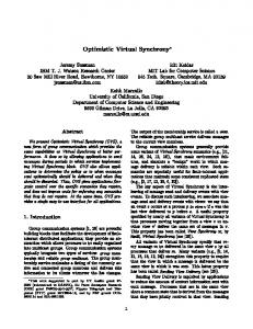
2. Background on MLC PCM The wide resistance difference between the amorphous and crystalline states enables the concept of MLC PCM technology. Currently, we can find 2-bit MLC prototypes, but ITRS predicts higher densities (3 and 4) being achievable near to 2020 [1]. In MLC, the number of resistance levels increases exponentially with the number of bits stored in a cell, implying that the resistance band assigned to each data value must be narrowed accordingly. Therefore, MLC read/write operations need dedicated control mechanisms for read and write operations which are described in this section. MLC Write: In MLC, a specified resistance band is assigned to represent a specific data value and the write process must be accurate enough to program the cell. To this end, MLC PCM controllers widely rely on a repetitive program-and-verify technique [2, 21]. When write circuit receives a request, it first injects a RESET pulse with large voltage magnitude to completely RESET the cell, and then injects a sequence of SET pulses with lower voltage magnitudes. After each SET pulse, the circuit reads the cell resistance value and verifies whether it falls within the target resistance range; if so, the write process is completed. Otherwise, the circuit recalculates the write parameters and repeats the steps until the target resistance is formed. Due to process variation and composite fluctuation of nano-scale devices, non-determinism arises for MLC PCM writes [11, 34]. The cells storing a memory line may take a variable number of iterations to finish. Furthermore, the same cell requires different number of iterations when writing different data values. Thus, to write a memory line, the worst case write latency is variable. This is a known problem for PCM and many previous studies proposed techniques to either speed up MLC write accesses or protect the processor from the negative impacts of slow writes [36]. Besides inferior performance, PCM writes bring two main challenges: (1) limited cell lifetime, and (2) considerable energy consumption per write access. These challenges are even exacerbated in MLCs because of the iterative pulses required during write operation. Limited cell lifetime can be dealt with by using combinations of three strategies: (1) reducing the total number of cell updates by differential write [4,17,36], (2) spreading cell wear out [24, 27, 36], and (3) tolerating cell failure [5, 26, 28, 31]. Most promising strategies are those in the first category because, in addition to reducing cells’ wear out, they reduce the required energy for write operation. Although all known wear management and error correction schemes are fully applicable to the SPCM architecture, our baseline system assumes differential writes [36], as it can potentially reduce both wear and energy. MLC Read: Reading a PCM cell involves sensing the resistance level and mapping it to its corresponding data value. Read operation usually applies binary search to determine MLC content bit by bit (Figure 1).
RB
100
60 40 20
2 Note
that RB also can be an alternative to the row buffer in memory side.
hi 3 pm d1 m pm d2 m pm d3 m plo 1 m plo 2 m plo 3 ca ne al de du p fa ce si m fe rr et vi ps m
hi 2
pm
p-
hi 1
0 m
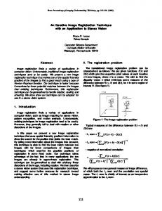
According to the iterative read mechanism described above, the MSB of a PCM cell can be determined in early cycles of a read access irrespective of the LSB. This asymmetry brings an opportunity to reduce read latency and energy consumption of MLC PCM. As a solution, we expect that by pairing two consecutive data blocks and rearranging them horizontally in an array of cells where each cell stores one bit of the first line and one bit of the other. Hence, MSBs hold the data block with odd address and LSBs hold the block with even address, as shown in Figure 2. This reduces the average memory access latency since the block at odd address is retrieved in the first read step (as in SLC mode), while reading the other block takes the latency of 2-bit MLC read. Based on our observation when a read request at an odd address arrives, the next line with even address is requested shortly most of the times as a result of spatial locality. Hence, if we buffer the most recently read blocks from the PCM array, requested by the LLC controller, in a Read Buffer (RB) 2 , it might not be necessary to spend extra read iterations to extract
LLC
80
p-
3. Motivation
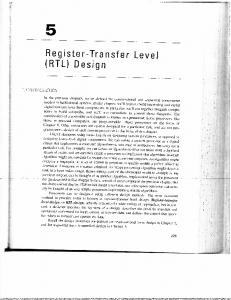
the MSB line (as reference). Even in case of miss in RB, the LLC may have already cached the MSB block. We define Odd-Block Hit-Rate (OBHR) as the frequency of odd block hits in either RB or LLC, required to realize a read for an evenaddress block. Overall, higher average OBHR means smaller number of redundant accesses to the PCM array. Figure 3 gives the breakdown of OBHR. As it is shown in Figure 3, approximately 63% of requested odd blocks are found in RB. Intuitively, to read the requested data block with even address, the controller can first request the odd block from RB or LLC. If it fails, it reads this block from the PCM array. Notice that if the odd block is found in the LLC, it must be clean.
m
At the first step, the circuit compares the resistance to a reference cell. The reference cell’s resistance is chosen as roughly the middle of the whole resistance window. Depending on the comparison outcome, (1) the MSB is determined (a larger resistance indicates the stored bit is “0”; otherwise, it is “1”) and (2) the circuit chooses the next resistance reference for the next bit. This process iteratively continues until all bits are read. In general, a read operation for an n-bit MLC requires n iterations to complete, which is not desirable as the processor performance highly depends on memory read latency. A straightforward solution to this problem is to perform all comparisons in parallel and complete the read in one step. Since such a parallel sensing requires 2n -1 copies of the read circuits for an n-bit MLC PCM, it increases sensing current and poses hardware overhead in addition to fabrication constraints which make it impractical. As such, bit by bit read mechanism is widely used in current MLC PCM prototypes [2, 23].
Figure 2: (a) Conventional vertically aligned bit mapping. (b) Striped bit mapping.
RB/LLC OBHR (%)
Figure 1: 2-bit MLC read mechanism. Reference resistance levels are driven from [35] for 2X difference between adjacent regions in order to tolerating 1 minute drift.
Figure 3: Breakdown of the OBHR in RB and LLC. The configuration reported in Section 4.1 augmented with a RB of 20 slots is used in our simulations.
4. The Striped Phase Change Memory Based on the above motivation, SPCM seeks for a better performance by pairing two memory lines. For simplicity, we assume that the two paired blocks differ in the lower bit of the block address. This rearrangement requires some modifications in read and write operations. Read: When a block with odd address is read, it is retrieved within the first iteration (RD1 in Figure 4). Given an even block address, the SPCM controller requires to know the MSBs of the cells to use as reference. So, the SPCM controller first examines the RB and LLC in parallel for the odd block. On a hit (either in RB or in the LLC when the odd block is clean) the requested even block can be retrieved in approximately one iteration (RD2). In the worst case, the odd
Figure 4: Timing diagram for (a) all possible read requests (RD1: Read odd block; RD2: Read even block/buffered odd block; RD3: Read even block/NOT buffered odd block), (b) even block write requests (WR1: Write even block/NOT buffered odd block; WR2: Write even block/buffered odd block), and (c) odd block write requests (WR3: Write odd block/NOT buffered even block; WR4: Write odd block/buffered even block). We assume 1, 3, and 6 time units for buffer, one MLC read sequence, and write latencies respectively.
block does not present in RB or LLC (or when it is dirty in LLC), the memory controller calls for reading the odd block as well; hence, the read process lasts as long as that in the baseline memory (RD3). Fortunately, the odd block usually exists in the RB due to spatial locality, enhancing the chance of performance improvement. Write: Regarding line striping, all updates to a memory line necessitates writing both MSB and LSB blocks at once. Therefore, the memory controller first attempts to obtain the partner block from the LLC; if it fails, the SPCM is accessed by using the read mechanism described above. In case of updating an even block, the partner odd block must be written as well. If the odd block is not cached (WR1 in Figure 4), it should be retrieved in one iteration of MLC read operation. Otherwise, the controller obtains it by accessing the cache (WR2). Similarly, when an odd block is requested for write, its partner even block must be written back too. In the worst case, the even block is not cached (WR3) and the controller needs to extract the old odd block (as a reference for reading the even block) and the partner even block itself. However, when the even block is cached (WR4), it can be obtained by accessing the cache. Finally, buffered blocks are scheduled to be written to the main memory in next cycles (see [10] for read/write-aware scheduling mechanisms). 4.1. Evaluation Settings Throughout evaluation, we use same configuration parameters for the baseline system used in similar studies. Infrastructure: We perform microarchitectural level, execution-driven simulation of a processor model with UltraSPARCIII ISA using GEMS [19] and Simics toolset [18]. The simulated CMP runs Solaris 10 operating system at 2.5GHz. We use CACTI 6.5 [20] to obtain timing, area, and energy estimations for the main memory and caches. Note that we used the approach given in [17] to adapt CACTI for PCM. For all the components except for the PCM main memory that
Table 1: Main characteristics of the evaluated system. Processor and on-Chip Memories quad-core, SPARC-III, out-of-order, 2.5GHz, Solaris 10 OS L1 caches Split I and D, UCA 32kB private, 32B, LRU, writeback, 3-cycle hit L2 cache NUCA 4MB shared, 8-way, 64B, write-back, 50cycle hit Memory Controller 20 slot read/write/read-response queue buffers PCM Main Memory SPCM Controller† 2MB SRAM, 16K slots P-WRQ (6ns, 22mm2 ); 2KB SRAM, 20 slots RB (0.7ns, 0.65mm2 ), 4.7K 2-input NAND gates control logic 667MHz, DDR3 1333MHz, 8B data bus, single-rank, DIMM 8 banks off-chip 128MB DRAM shared, 8-way, 128B, writeL3 cache (LLC) back, 63-cycle hit (25ns) MLC PCM 48ns/40uA/1.6V/5.5nJ read, 40ns/300uA/1.6V RESET, 150ns/150uA/1.2V SET, 15ns/100-996uA/upto 32 iterations partial set, 531.8nJ for all line updates Cores
†
SPCM Controller is not used in the baseline system.
uses a Low-Operating-Power (LOP) process, we use 32nm ITRS models, with a High-Performance (HP) process. System: We model a 4-core CMP detailed in Table 1. The system has three levels of caches: separated L1 instruction and data caches that are private for each core, an L2 cache that is logically shared among all the cores while physically structured as static NUCA, and an off-chip DRAM cache. SPCM Controller: SPCM requires a controller to handle read and write operations. We use a 2KB RB within the SPCM controller. To prevent traffic overloading on the memory bus, we assume both the LLC and SPCM controller are placed in DIMM side. Since the memory bus is physically wrapped between L2 (on CPU side) and LLC, the SPCM will not pose unnecessary traffic on the bus. PCM main memory: Our baseline architecture of a 2-bit PCM memory subsystem is shown in Figure 5. Similar to
Table 2: Characteristics of the evaluated workloads. MPKI OBHR† Lifetime (years) SPECCPU, 2006, 4-Application Multi-programmed (MP) mp-hi1: mcf-bzip2-omnetpp-xalancbmk 10.99 (H‡ ) 0.78 14.89 mp-hi2: milc-leslied3d-gemsfdtd-lbm 19.28 (H) 0.93 20.74 mp-hi3: mcf-xalancbmk-gemsfdtd-lbm 10.77 (H) 0.77 6.7 mp-md1: mcf-gemsfdtd-povray-perlbench 7.36 (M) 0.89 4.88 mp-md2: mcf-xalancbmk-perlbench-gcc 7.61 (M) 0.84 7.65 mp-md3: gemsfdtd-lbm-povray-namd 5.15 (M) 0.72 8.64 mp-lo1: gromacs-namd-dealii-povray 0.51 (L) 0.86 35.56 mp-lo2: perlbench-gcc-dealii-povray 2.11 (L) 0.97 20.02 mp-lo3: namd-povray-perlbench-gcc 1.01 (L) 0.98 29.84 Workload
† ‡
Workload MPKI OBHR Lifetime (years) PARSEC-2, 2009, Multi-threaded (MT) caneal 6.86 (M‡ ) 0.6 5.86 dedup 1.27 (L‡ ) 0.99 25.8 facesim 4.91 (M) 0.23 12.7 ferret 3.53 (M) 0.94 13.59 vips 1.63 (L) 0.98 24.03 For all benchmarks Min 0.51 0.23 4.88 Max 19.28 0.99 35.56 Average 5.93 0.82 16.49
Odd-Block Hit-Rate (OBHR); average OBHR for all benchmarks is 82% (63% in RB, and 19% exclusively in the LLC). L: below 3.0; M: between 3.0 and 10.0; H: above 10.0.
DRAM, PCM is based on DIMM with 8 PCM chips. A large DRAM shared cache is used to debilitate the problems of long write latency and limited endurance of PCM devices. The DRAM last-level cache has a default size of 128MB. We will also examine 16MB, 32MB, 64MB, and 256MB cache sizes later in Section 7. Due to the non-determinism of MLC PCM write latency, we adopt the universal memory interface proposed by Fang et al. [7]. We use write-pausing with adaptive write-cancelation policy proposed by Qureshi et al. [22] that can pause an on-going write in order to service a pending read request. Furthermore, we rely on randomized Start-Gap algorithm [24] for low-overhead wear leveling. For further lifetime and write energy efficiency, differential write mechanism is enabled. In this scheme, before a PCM block is written, the old value is read and compared to the new data, and only cells that need to change are then programmed [4, 36]. Considering the baseline, we choose a granularity of 64B for write circuit [9] to amortize the write driver’s area. As such, baseline needs two rounds to write a line (128B). In the SPCM with 128B data blocks, we use the same hardware and hence need four rounds while writing. There is no area overhead but the energy/latency costs should be accounted. In contrast, we should double up the number of read circuits to prevent latency overheads which imposes 2× read energy and has a negligible area overhead.
Figure 5: The baseline architecture
MLC PCM model: Table 1 summarizes the timing and power characteristics of the modeled 2-bit MLC PCM. We evaluated the MLC design with a resistance distribution that can tolerate
resistance drift of at most one minute (Figure 1), after which a refresh command is issued. This provides a readout current of 40uA and RESET and SET current of 300uA and 150uA, respectively. These values are obtained using a model by Kang et al. [15] that calculates the minimum programming current required for a successful write operation. Following this model, experiments show that program-and-verify takes at most 32 iterations to complete. Workloads: We used parallel programs in PARSEC-2 suite [3] as multi-threaded workloads and a set of programs in SPECCPU2006 benchmarks [29] for multi-program applications. Particular applications are chosen for their memory intensity and we did not consider a benchmark if its main memory access rate is low in order to better analyze the impact of memory system on overall system performance. Regarding input sets, we use Large set for PARSEC-2 applications and Sim-large for SPECCPU2006 workloads. We classify benchmarks based on their LLC’s Misses per Thousand Instructions (MPKI) when running alone in a 4-core system detailed in Table 1: each workload is either high-miss (H) if MPKI is greater than 10, medium-miss (M) if MPKI is between 3 and 10, or low-miss (L) if MPKI is less than 3. Table 2 characterizes the evaluated workloads. 4.2. Evaluation Results and Discussion We developed the SPCM system over the baseline system shown in Figure 5. Using the SPCM, we expect considerable reduction in memory access latency (especially for reads) compared to the baseline system. This is also observed in the first column of Table 3 that reports reduction in memory access latency; it shows up to 38.5% (31.2%, on average) reduction in memory access latency for the evaluated configurations. Table 3 also shows that the IPC improvement (as a system performance metric) is about 8.02%, on average (and up to 23.8% for mp-hi2). As expected, we have more performance gain in memory-intensive benchmarks, especially those which are read-dominant. Therefore, based on the information given in Table 2, workloads like mp-hi1 with larger MPKI can better benefit from SPCM. In the SPCM system, once a block is evicted from the LLC, it should be combined with its partner before writing
Table 3: Impact of using SPCM on different metrics (%). Graphical presentations can be found in Figures 9-13. Workload mp-hi1 mp-hi2 mp-hi3 mp-md1 mp-md2 mp-md3 mp-lo1 mp-lo2 mp-lo3 MP-HM∗
Mem. Latency 37.38 35.86 24.22 30.15 30.70 32.75 33.09 34.26 30.71 32.12
IPC 16.47 23.82 13.97 10.06 8.89 3.06 2.59 5.29 3.23 9.3
Energy -20.91 -27.76 -28 -25.16 -23.71 -31.92 -28.61 -25.99 -27.64 -26.76
EDP† 10.07 10 -4.04 -10.26 -2.43 -25.34 -21.92 -15.03 -21.86 -10.68
Updates‡ 29.7 37.3 36.6 34 33.2 39 39.2 38.2 33.1 35.5
caneal dedup facesim ferret vips MT-HM∗
27.25 38.51 18.90 31.67 32.49 29.76
6.61 3.33 8.38 8.94 2.02 5.79
-23.84 -24.7 -22.74 -26.88 -29.24 -25.55
-7.73 -20.5 -10.26 -14.25 -24.07 -15.81
31.9 31.6 29.9 33.7 35.5 32.5
Min Max H-Mean∗
18.90 38.51 31.28
2.02 23.82 8.02
-31.92 -20.91 -26.33
-25.34 10.07 -12.58
29.7 39.2 34.4
† ‡ ∗
Energy-Delay-Product (EDP) The percentage of increase in number of updated cells. HM means Harmonic-Mean.
in the associated cell array. For example, consider block A which becomes dirty at t1 and is going to be written back to the PCM array at t2 , but its partner block B is not dirty before t3 > t2 . So, A ∪ B is written to the associated PCM cell array at t2 . Subsequently, block B becomes dirty at t3 and is evicted from the LLC at t4 , requiring A ∪ B to be written on the same cell array. Then, the write-back traffic in the SPCM system is nearly twice the baseline. This is the main cause of increase in number of updated cells, which ultimately leads to shorter memory lifetime and more energy consumption. This energy overhead is higher than the performance gain achieved by the SPCM for most of the applications. The last two columns of Table 3 shed light on this fact by reporting the Energy-Delay-Product (EDP) as a metric for efficiency as well as the amount of growth in the number of updated cells. Notice that the number of updated cells in Table 3 are measured after applying differential write technique. As it can be seen, except for highly memory-intensive applications which benefit from striping, other benchmarks show large reduction in EDP. Therefore, we can conclude that using a pure SPCM is not worthwhile and we need to find a way to alleviate its energy/lifetime overheads.
5. Durable SPCM We develop an additional architectural innovation to the SPCM in order to prolong its lifetime and relieve its energy consumption by carefully scheduling the write operations. The main goal of this scheduling is to pair write-back requests in odd and even addresses and send them to the SPCM memory at once as a pair-write. By this modification, we expect that the energy consumption and number of writes per cell become close to those of the baseline system.
5.1. Pairing Write Queue: P-WRQ In this section, we first present the abstract concept of our solution through an example. Then, we support our idea with some observations on the efficiency of our solution. It was mentioned in Section 4.2 that any update in block A and/or B (which are paired) requires writing A ∪ B. Therefore, both blocks must be written onto the SPCM when one of them is evicted from the LLC for write-back. In this example, we assume blocks A and B are evicted in t2 and t4 , respectively (t4 > t2 ). We suggest to postpone writing block A until t4 . Thus, compared to the conventional design, SPCM gets a same-sized write update (occurred at t4 ).
Figure 6: Abstract Concept of Waiting Room. R-marked people are ready to go, because the couple is in the room; The mates of exclamation-marked (!) people are not in the LLC (previously have gone), so they don’t need to wait for anyone; Lastly, W-marked people must wait for their mate’s arrival.
Waiting room: Based on the above example, we must keep one block somewhere waiting for its partner block. We call this place “Waiting Room” to convey the abstract concept of waiting, as shown in Figure 6. Once a block is evicted from the LLC, it enters the waiting room to be scheduled for writing. In contrast with conventional write queues, the leaving priority is not in FIFO order.Instead, we define a SPCM-aware priority order as follows: 1. Ready: Both partner blocks are present in the room (marked with ‘R’). They are ready for pair-write operation. 2. Confused: One block is in the room (marked with ‘!’), and its partner block is not in the LLC. In this case, it is not required to wait for the partner block. 3. Waiting: One block is in the room (marked with ‘W’) while its partner block is not, but it can be found in the LLC. Now, the block must wait for its partner block to become dirty and finally evicted from the cache. We also consider FIFO order as the minor precedence, which means that in each priority, the one that comes earlier can go first. Figure 6 clarifies this scheduling by exhibiting a waiting room in the society. When the write buffer is full, two blocks are selected to leave. If both of them are in ready state, the scheduler sends them to the corresponding SPCM bank for writing. When one block is in confused state, the memory controller first accesses the SPCM bank to obtain the partner block and buffers it, then both page are sent for writing. Ultimately, if there is no ready
or confused block, the scheduler sends the first waiting block inevitably (at cost of redundant cell updates).
the number of writes in the SPCM system with P-WRQ gets closer to that of the baseline system. 5.3. Energy Restoration
R
100
!
W
80 60 40 20 s
et
vi p
m
rr
si ce
fa
fe
l
p du
de
3
ea
ca n
2
lo
m
p-
1
lo
lo m
p-
d3
pm
d2
m
m
p-
p-
m
3
d1 m
p-
m
m
2
hi p-
m
hi
pm
m
hi
1
0 p-
Distribution of each priority in P-WRQ evictions (%)
Figure 8: Percentage of each priority in P-WRQ ejections.
Using this architecture, we expect that the energy and lifetime overheads incurred by the SPCM system can be recovered. This is achievable when almost all ejected blocks are in ready state. Figure 8 plots the priority distribution of the ejected blocks from write queue. As it is shown, about 72% of the ejected blocks are of ready type. Based on this observation,
p-
lo 2 pM lo3 PH M ca ne a de l du fa p ce si m fe rr et v M ips TH H M -M ea n
P-WRQ SPCM
m
m
p-
d3 lo 1
Pure SPCM
m
d2
m p-
m p-
m
hi 3
m
p-
m
hi 2 m
m
p-
hi 1
p-
p-
d1
Baseline
1.4 1.2 1 0.8 0.6 0.4 0.2 0 m
Figure 7 illustrates the proposed architecture for pairing write queue. In this design, we supply a pairing write queue to the SPCM controller on DIMM with the eviction policy described before. An arbiter logic is required to determine which block can leave the queue. It requires knowing the state of all buffered blocks. Firstly, it should figure out how many blocks are ready (counter ‘R’ indicates the number of ready blocks). If there is any, it chooses the first couple to leave (pointers ‘P1’ and ‘P2’ contain the location of chosen ready blocks). But, if there is no ready block, it gets the number of confused blocks from counter ‘C’, and chooses the first one pointed by ‘P3’. The partners of confused blocks are retrieved from the SPCM and buffered. Finally, if there is no confused block either, the arbiter selects the head of the queue (which is waiting) and fetches its partner from the cache. Note that, in all transactions including buffer ejection and injection as well as the LLC updates, all counters and pointers are updated in the background.
m
5.2. Architecture
Normalized Energy Consumption
Figure 7: Pairing WRQ architecture for SPCM system
Figure 9 shows the impact on energy consumption of a SPCM system with P-WRQ and a SPCM system without P-WRQ. The SPCM system with P-WRQ has only 0.7% energy degradation, on average (1.3% improvement in MP applications and 4.6% degradation in MT programs). One can observe that in workloads where ready blocks are dominant, the SPCM with P-WRQ dissipates much less energy compared to the system without P-WRQ (see Figure 8). Highly memory intensive applications such as mp-hi1 running on the proposed architecture do not consume more energy than the baseline system, but they achieve improvement mainly because of data holding in P-WRQ. On the other hand, applications like caneal (10%) and ferret (13%), that have a great number of confused blocks, are less influenced by P-WRQ. Overall, combining P-WRQ with the pure SPCM system can save energy.
Figure 9: Impact on energy consumption.
5.4. Impact on Performance P-WRQ has a negligible effect on the memory access latency since all write operations are off-path and pausing them is not costly. Thus, we expect nearly no change in memory access latency, as it is shown in Figure 10. In this figure, the SPCM system with P-WRQ achieves an average improvement of 31%, similar to the system without P-WRQ. Figure 11 also shows the overall system performance improvement. We can observe that P-WRQ does not harm performance improvement while saving energy. The SPCM system with P-WRQ shows 3% to 25% IPC improvement (10%, on average). Notice that small variations in system performance are originated from P-WRQ’s capability of data holding. 5.5. EDP Enhancement With the energy saving and performance gain of the SPCM with P-WRQ, we expect improvements in total Energy-Delayproduct (EDP). As it is illustrated in Figure 13, SPCM with P-WRQ achieves up to 37% reduction in EDP (12%, on average) and this improvement is more noticeable on benchmarks
Normalized EDP
15 10 5
d3 plo m 1 plo m 2 pM lo3 PH M ca ne a de l du fa p ce si m fe rr et v M ips TH H M -M ea n
d2
m
m
m
p-
p-
m
i3
d1
m m
p-
ph
i2
pm
Pure SPCM
P-WRQ SPCM
p-
hi 1
h m i2 pm hi3 pm m d1 pm m d2 pm d m 3 plo m 1 plo m 2 m p-l p- o3 hm ea ca n ne a de l du fa p ce si m fe rr et m vip t-h s m ea hm n ea n
p-
m
m
p-
hi 1
0
Baseline
1.4 1.2 1 0.8 0.6 0.4 0.2 0 m
IPC Improvement (%)
20
P-WRQ SPCM
Figure 12: The impact of using SPCM system on IPL.
Pure SPCM P-WRQ SPCM
25
m
m
m
Figure 10: Impact of using SPCM on memory access latency. 30
m
ph
d3 plo m 1 plo m 2 pM lo3 PH M ca ne a de l du fa p ce si m fe rr et v M ips TH H M -M ea n
d2
m
m
p-
m
i3
d1
m
p-
m
p-
i2
ph
m
m
ph
m
ph
i1
0
i1
10
ph
20
Pure SPCM
h m i2 pm hi3 pm m d1 pm m d2 pm d m 3 plo m 1 plo m 2 pM lo3 PH M ca ne a de l du fa p ce si m fe rr et v M ips TH H M -M ea n
30
Baseline
1.8 1.6 1.4 1.2 1 0.8 0.6 0.4 0.2 0 m
Normalized IPL
40
m
Memory Access Latency Improvement (%)
Pure SPCM P-WRQ SPCM
50
Figure 11: IPC improvement using the SPCM system.
Figure 13: Impact of using SPCM on EDP.
with more memory accesses. The main reason is that the performance gain in these benchmarks is large enough to hide the negative impact of energy loss. For instance, while mp-lo1 shows an increased energy consumption of about 5.34%, IPC improvement of about 2.88% results in 1% enhancement of EDP. Finally, benchmarks for which both energy and performance are improved (such as facesim) demonstrate considerable EDP gain.
SPCM with and without using P-WRQ on the overall IPL. By comparing Figures 12 and 13, it is obvious that the trend of variations in IPL is approximately inverse of EDP. The reason is that both of them are functions of energy consumption and system performance. As it is shown, the SPCM system brings about 17% improvement in IPL, on average, without degradation in any benchmark. It is remarkable that using P-WRQ has an undeniable impact on the overall IPL. Therefore, it can be concluded that using SPCM memory system with P-WRQ is much more efficient than the baseline, even with shorter lifespan.
5.6. Impact on Lifetime In addition to energy consumption, lifetime is another concern in PCM memory systems. Unfortunately, pairing two memory lines in a 2-bit MLC cell array has an adverse impact on the overall PCM lifetime. On the other hand, increasing system performance causes higher write bandwidth even though both have an identical number of writes. In our experiments when an ideal wear leveling (e.g. those in [24, 27]) is used, we observed that SPCM system shortens the average lifespan for about 24%. However, lifetime itself is not a good measurement for efficiency. To this end, we define Instructions per Lifetime (IPL) as the number of executed instructions during the lifetime of the device which can be given by IPL =
B × F × Inst S ×Wmax
(1)
where B is bytes per cycle written to the PCM array (write bandwidth), F is system frequency (2.5GHz), Inst is the number of executed instructions, S is the size of PCM memory (4GB), and Wmax is the maximum number of writes to a PCM cell (see [25] for lifetime equation). A larger IPL reveals a more effective memory system. Figure 12 shows the impact of
6. Scalability Analysis The SPCM is a general approach and can be also applied to higher bit storage level PCMs. This means that more than two blocks can be grouped together and stored in one MLC array in an striped manner. In this section, we utilize different models to observe the impact of using N-bit SPCM system on different metrics and costs. 6.1. Read Latency Improvement We develop an analytical model to investigate the impact of storage density on the average memory latency of the SPCM, considering a normal distribution for all possible data patterns. Foremost, a recursive relation can be given as L(1) = P × LB + (1 − P) × LM to calculate the latency for extracting the first bit of the cell (the MSB), and L(n) = P × LB + (1 − P) × (LM + L(n − 1)) for lower bits, where n is the bit number in the cell from the next MSB to the LSB. The first term declares that when a desired block is in the RB or the LLC (with a probability of P), it can be retrieved in LB cycles (for simplicity
Estimated Memory Access Latency Gain Ratio 0.8
4.0
N=2 N=3 N=4
0.6
3.0
0.5 0.4
0.31
0.3
2.5 2.0 1.5
0.2
1.0
0.1
0.5
0
0
0.2
0.4
0.6
N=2 N=3 N=4
3.5
Espcm/Ebase
0.7
1-Lspcm/Lbase
Estimated Memory Access Energy Loss Ratio
0.8
0.0
1
1.005
0
0.2
0.4
P
0.6
0.8
1
P
Figure 14: Analytical estimation for memory access latency improvement in 2-, 3-, and 4-bit SPCM.
Figure 15: Analytical estimation for memory access energy overhead in 2-, 3-, and 4-bit SPCM with P-WRQ.
we assumed a fixed LB , but it depends on the latencies of LLC and RB). The second term states that if it is not cached or buffered, we need to spend LM cycles in order to read the block from the SPCM, and in case of not being the MSB, L(n − 1) additional cycles are also required for extracting the upper n − 1 bits (as the reference for read circuit). Then, for simplification, we describe the average of expected values for our model as i �� 1 N �
6.2. Write Energy Overhead
Lspcm =
∑ N i=1
1 − (1 − P) × P × LB + (1 − P) × LM P
(2)
where N is the cell density level, LB is the average latency of accessing the buffer and cache, LM is the latency of one iteration of reading from MLC PCM (120 cycles), and P is the probability of a block being buffered or cached. On the other hand, it is clear that the average latency of accessing the memory in the baseline system can be given by Lbase = P × LB + (1 − P) × LM × N
(3)
which means that if the block was cached or buffered with a probability of P, it can be obtained in LB cycles; otherwise, N × LM cycles would be required. Figure 14 plots curves of the expected memory access latency ratio (1 − Lspcm /Lbase ) for different cell density levels (i.e. N=2, 3, and 4). When P = 0, half of the blocks (those are at odd addresses) can be extracted within 50% of the total required latency for a 2-bit MLC which means 25% overall latency improvement as shown in Figure 14. As P increases, we achieve more improvement in access latency until P < 0.9. However, when 0.9 < P < 1.0, most of read requests are serviced in the LLC and RB, and therefore, we have less latency gain by using SPCM. Our simulation results (Figure 10) are also matched with this model. For example, ‘×” sign on N=2 curve in Figure 14 represents the value calculated by simulation; the value of P ' 0.82 is also determined by simulation for the evaluated workloads (see OBHR in Table 2).
In case of using more than two bits per cell, the ejection priority order in P-WRQ should be modified. In this case, the most prior group to be written is the one whose all partners are in the queue and the next priorities are those that have less number of buffered partners. This of course imposes latency overhead in the arbiter logic which cannot be mathematically modeled and requires synthesis evaluations to be obtained. For the energy overhead of using SPCM along with P-WRQ, however, we can write N
� � N N−i P (1 − P)i EM i=1 i
Espcm = P × EB + (1 − P) × ∑
(4)
where N is the storage level, EB is the energy for writing a block inside the buffer (P-WRQ) that is about 100.3pJ, EM is the required energy for writing an N-bit MLC array consisting of N cells that is 272.5pJ per cell, and P is the probability of a block being in the queue. The first term shows that in case of being buffered (with a probability of P), the write operation is redirected to P-WRQ which dissipates EB joules. The second term states that if the block was not buffered, for each partner of the group that is not in the buffer, one write operation is required (EM joules). Based on this model, if none of the partner blocks is in the P-WRQ (P = 0), N × EM joules would be consumed to write them back separately. For comparison, the energy consumption in the baseline system can be estimated as Ebase = P × EB + (1 − P) ×
EM N
(5)
where the first term indicates that if the block is in the buffer, it would dissipate EB joules. The second term states if it is not buffered, EM /N joules would be consumed. Note that in the baseline, an S-bit block lies on S/N number of MLCs. Figure 15 plots the expected memory access energy ratio curves (Espcm /Ebase ) as a function of P.
Percentage of Pair-Write Coverage
P-WRQ Latency/Energy Costs 5
P32 P16
60%
40%
16MB 32MB 64MB 128MB 256MB
20% 10
8
P-WRQ Si
6
4
ze (MB)
128
2
0 1632
64
ac
MC
DRA
ize he S
) (MB 0%
0
2
4
6
8
P-WRQ Size (MB)
(a)
10
12
120 3.5
P32 100
3 P64
2.5
80
2
60
1.5 40 P128
1 0.5 P256 0
14
140
4
Access Latency (ns)
P64
80%
256
12
160 P16
4.5
P128
Energy per Read Access (nJ)
LLC 256M P-WRQ 512K P256
100 90 80 70 60 50 40 30 20
Pair-Write Coverage
Pair-Write Coverage
100% P256
0
20
Access Latency Energy per Access 2
4
6
8
10
12
14
0
P-WRQ Size (MB)
(b)
(c)
Figure 16: The result of sensitivity analysis over the P-WRQ size versus LLC capacity in (a) 3D and (b) 2D forms. (c) Latency/Energy costs for different P-WRQ sizes. Selected design corners are shown in (b) as Px where x is the size of LLC.
7. Design Space Exploration To evaluate the efficiency of our proposed striping scheme under different settings, we conduct simulation experiments on different designs with different last-level cache capacities, and investigate the performance gain and energy loss for each design. Since the desirable number of slots in P-WRQ highly depends on the partner eviction intervals (number of irrelevant write-back requests between two partner block evictions from the LLC), we first performed a sensitivity analysis on the size of P-WRQ versus different sizes of LLC. Figure 16-b depicts the average percentage of pair-write coverage for different LLC capacities and P-WRQ sizes. By interpolating values between two simulated design-points, we can estimate pair-write coverage for other capacities (Figure 16-a). For each design the maximum percentage of pair-writes would be roughly saturated in a specific design-point which indicates the adequate size of P-WRQ (e.g. P128 for LLC capacity of 128MB in Figure 16-b). In large capacities, the LLC intends to keep data blocks rather than putting them out. Therefore, P-WRQ which collects dirty evicted blocks from the LLC, would be less polluted. This fact shortens the average partner eviction intervals and brings an opportunity to reduce the size of P-WRQ for larger LLCs. Hence, according to Figure 16-c, the latency/energy overheads would be smaller. Figure 17 compares the performance gain of SPCM memory system with P-WRQ for different LLC capacities. With a
Average IPC of Baseline
Speedup (%)
As we discussed before, when P = 0, the energy consumption is exactly N 2 × higher than the baseline since the number of updated cells in the SPCM system is N× greater than that of the baseline system and each partner block is written back in N different times. Obviously, if P = 1, we have no energy overhead because all write-backs occur at once. However, we probably have some improvement when 0.75 < P < 1.0 because not only most of the partners which are ejected from the queue have been written in time, but also some writes are handled in the buffer. Figure 9 shows that for benchmarks with medium rate of P (see Table 2 for OBHRs) we have some energy improvement.
40 35 30 25 20 15 10 5 0 -5
4.04
6.32
7.21
9.30
9.18
Quartiles
16M
32M
64M
128M
256M
DRAM Cache (LLC) Capacity Figure 17: The impact of the LLC capacity on overall speedup in a SPCM system with P-WRQ. Values are presented in candlestick style indicating maximum, minimum, mean, and quartiles. The average IPC for each design is shown above each bar.
small LLC, e.g. 16MB, a large number of memory accesses are realized, for which the SPCM system worked very well and provided considerable performance gain. However, small LLCs increase the main memory bandwidth requirement and make it a performance bottleneck for the system which result in a declination on average IPC. Additionally, small LLCs require large P-WRQ with long access latency. Due to its large capacity, maybe many read requests are serviced in PWRQ taking several cycles (300 cycles for a 12MB P-WRQ). Therefore, although small LLCs can improve the overall performance of the SPCM system, they are not proper settings to be used in PCM for two reasons: (1) a small LLC poses write stress on PCM devices leading to early wear out and extra write energy consumption, and (2) it slightly improves the IPC value (compare the average IPC of 9.3 for a 128MB SPCM system to the average IPC of 4.04 for 16MB SPCM system). On the other hand, large LLCs are slower than smaller ones due to wire, decode, and sensing amplifier delays, which can potentially harm performance gains. Figure 18 illustrates the impact of using SPCM system with P-WRQ on memory access energy with respect to the baseline
PCM Energy Loss (%)
15
Quartiles
10 5 0 -5 -10 -15
16M
32M
64M
128M
256M
DRAM Cache (LLC) Capacity Figure 18: The impact of LLC capacity on energy consumption for a system using SPCM with P-WRQ compared to the baseline. Values are presented for maximum, minimum, mean, and quartiles.
system. This figure considers only the energy dissipated in the main memory for the SPCM and baseline systems. It is obvious that the total amount of memory energy consumption would be lower for large LLCs because of smaller number of memory accesses. As can be seen in the figure, the average energy loss in all settings is roughly identical. So, using larger LLCs hides the SPCM performance potential and has no benefits over the smaller ones. As shown in Figure 17, the average speedup has a reverse relation with LLC capacity, while Figure 18 reveals almost no change in energy loss for different LLC sizes. Additionally, large LLCs impose extra dynamic power and area overheads. Worse, larger LLCs consume more leakage energy and have longer access latency. Therefore, there is a tradeoff between the LLC capacity and speedup. Putting these all together, we can conclude that 128MB is a proper compromise between performance gain and power costs.
8. Related Work In this section, we focus on important related studies concerning innovative techniques to favourably effect on overall system performance and PCM lifetime. To reduce the latency of the system’s critical path at architectural level, especially for read operation, certain topical micro-architectures tend to take advantage of MLCs high density along with immediate reaction to read requests. Among them, two classes can be categorized: first, based on the resume capability of iterative program-and-verify process, the Write Pausing and Write Cancelation schemes are proposed in [22], which tries to pause/cancel an on-going write in support of prompt response to a superior read request directed to same memory bank; second, aggregating benefits of both SLC and MLC in a storage system, strategies in [6,23] try to dynamically transmute between these two states. Dong and Xie in [6] proposed AdaMS, an adaptive MLC/SLC PCM design for file storage, which focuses on exploiting fast SLC response speed and high MLC density with the consciousness of workload
characteristic and lifetime requirement. MMS, a morphable memory system [23], also decides on bit-storage level of the physical memory page and subsequent recent transactions. To this end, a monitoring scheme determines operating at lower bit-capacity of the cell in order to obtain faster response time during a phase of low memory usage, or at high-density MLC when the program working-set is large. Some researchers pursue architectural techniques to reduce program-and-verify iterations. For example, [13] and [22] discriminate between the way of programming based on data pattern and previously stored data values. The experiments confirm that a safe decision on the write scheme selection can lead to a striking drop in program iterations, which sequentially causes enhancements in overall latency, energy and write-endurance of the non-volatile memories. In case of lifetime improvement, Qureshi et al. proposed Start-Gap [24], a simple but efficient analytical wear leveling technique to prevent too many write repetitions on a particular memory region. Taking advantage of asymmetric read latencies in multi-bit storage systems is another insight to improve system performance. Jiang et al. [12] proposed a large and fast MLC STTMRAM based cache for embedded systems where two physical cache lines are combined and rearranged to construct one read-fast-write-slow (RFWS) line and one read-slow-writefast (RSWF) line. Then, a swapping mechanism is applied for mapping write-intensive data blocks to RSWF lines and read-intensive blocks to RFWS lines. Striping also is already used in NAND-FLASH storage systems in different forms (vertical, horizontal, and 2-dimensional) for page alignment and combining physical pages from several dies to enlarge the granularity of flash arrays [8]. However, while multi-level STT-MRAM and Flash cells require modifications on fabrication process for different bit-storage densities, the structure of MLC PCM would not be changed. Yoon et al. [32] published a technical report presenting a new data mapping scheme for MLC PCM similar to what we proposed in this work to exploit the read latency asymmetry. Although the durability is one of the most important PCM concerns, they did not address the problem of doubling up the write bandwidth. Another complexity of the technique reported in [32] is that the OS must be aware of hardware for mapping policy.
9. Conclusion Among non-volatile memory systems, Phase Change Memory (PCM) is a promising candidate as a DRAM alternative for increasing main memory capacity especially in Multi-Level Cell (MLC) mode. However, one of the main challenges in an MLC PCM system is the linear increase in read access latency with respect to the cell storage level. In this paper, we took benefit of asymmetry in read mechanism and proposed a striping scheme for data alignment in a 2-bit MLC PCM (SPCM). Then, we augmented our design with a pairing write queue (P-WRQ) to prevent unnecessary write pressure on SPCM.
We also evaluated SPCM and P-WRQ with different configurations. Finally, we analytically investigated the scalability of SPCM with higher bit storage levels for potential performance gain and energy overhead. Our experiments showed significant improvement in system performance (10%) with a negligible energy overhead (0.7%).
References [1] A. Allan, D. Edenfeld, W. H. Joyner Jr, A. B. Kahng, M. Rodgers, and Y. Zorian, “2001 technology roadmap for semiconductors,” Computer, vol. 35, no. 1, pp. 42–53, 2002. [2] F. Bedeschi, R. Fackenthal, C. Resta, E. M. Donze, M. Jagasivamani, E. C. Buda, F. Pellizzer, D. W. Chow, A. Cabrini, G. Calvi, R. Faravelli, A. Fantini, G. Torelli, D. Mills, R. Gastaldi, and G. Casagrande, “A bipolar-selected phase change memory featuring multi-level cell storage,” IEEE JCCS, vol. 44, no. 1, pp. 217–227, Jan 2009. [3] C. Bienia and K. Li, “PARSEC 2.0: A new benchmark suite for chipmultiprocessors,” in MoBS, Jun 2009. [4] S. Cho and H. Lee, “Flip-N-Write: a simple deterministic technique to improve PRAM write performance, energy and endurance,” in MICRO, Dec 2009, pp. 347–357. [5] J. Condit, E. B. Nightingale, C. Frost, E. Ipek, B. Lee, D. Burger, and D. Coetzee, “Better I/O through byte-addressable, persistent memory,” in SOSP, Oct 2009, pp. 133–146. [6] X. Dong and Y. Xie, “AdaMS: Adaptive MLC/SLC phase-change memory design for file storage,” in ASP-DAC, Jan 2011, pp. 31–36. [7] K. Fang, L. Chen, Z. Zhang, and Z. Zhu, “Memory architecture for integrating emerging memory technologies,” in PACT, Oct 2011, pp. 403–412. [8] L. M. Grupp, J. D. Davis, and S. Swanson, “The bleak future of nand flash memory,” in Proceedings of the 10th USENIX conference on File and Storage Technologies. USENIX Association, 2012, pp. 2–2. [9] A. Hay, K. Strauss, T. Sherwood, G. H. Loh, and D. Burger, “Preventing PCM banks from seizing too much power,” in MICRO, Dec 2011, pp. 186–195. [10] S. Hudgens and B. Johnson, “Overview of phase-change chalcogenide nonvolatile memory technology,” MRS Bulletin, vol. 29, pp. 829–832, Oct 2004. [11] L. Jiang, Y. Zhang, B. R. Childers, and J. Yang, “FPB: Fine-grained power budgeting to improve write throughput of multi-level cell phase change memory,” in MICRO, Dec 2012, pp. 1–12. [12] L. Jiang, B. Zhao, Y. Zhang, and J. Yang, “Constructing large and fast multi-level cell stt-mram based cache for embedded processors,” in Design Automation Conference (DAC), 2012 49th ACM/EDAC/IEEE. IEEE, 2012, pp. 907–912. [13] L. Jiang, B. Zhao, Y. Zhang, J. Yang, and B. Childers, “Improving write operations in MLC phase change memory,” in HPCA, Feb 2012, pp. 1–10. [14] M. Joshi, W. Zhang, and T. Li, “Mercury: A fast and energy-efficient multi-level cell based phase change memory system,” in HPCA, Feb 2011, pp. 345–356. [15] D.-H. Kang, D.-H. Ahn, K.-B. Kim, J. F. Webb, and K.-W. Yi, “Onedimensional heat conduction model for an electrical phase change random access memory device with an 8F2 memory cell (F=0.15um),” Applied Physics, vol. 94, no. 5, pp. 3536–3542, Sep 2003. [16] K. Kilbok, “Main memory technology direction,” in WinHec, My 2007. [17] B. C. Lee, E. Ipek, O. Mutlu, and D. Burger, “Architecting phase change memory as a scalable DRAM alternative,” in ISCA, Jun 2009, pp. 2–13. [18] P. S. Magnusson, M. Christensson, J. Eskilson, D. Forsgren, G. Hallberg, J. Hogberg, F. Larsson, A. Moestedt, and B. Werner, “Simics: A full system simulation platform,” Computer, vol. 35, no. 2, pp. 50–58, Feb 2002.
[19] M. M. Martin, D. J. Sorin, B. M. Beckmann, M. R. Marty, M. Xu, A. R. Alameldeen, K. E. Moore, M. D. Hill, and D. A. Wood, “Multifacet’s general execution-driven multiprocessor simulator (GEMS) toolset,” CAN, vol. 33, no. 4, pp. 92–99, Nov 2005. [20] N. Muralimanohar, R. Balasubramonian, and N. Jouppi, “Optimizing NUCA organizations and wiring alternatives for large caches with CACTI 6.0,” in MICRO, Dec 2007, pp. 3–14. [21] T. Nirschl, J. Phipp, T. Happ, G. Burr, B. Rajendran, M.-H. Lee, A. Schrott, M. Yang, M. Breitwisch, C. Chen, E. Joseph, M. Lamorey, R. Cheek, S. Chen, S. Zaidi, S. Raoux, Y. Chen, Y. Zhu, R. Bergmann, H. Lung, and C. Lam, “Write strategies for 2 and 4-bit multi-level phase-change memory,” in IEDM, Dec 2007, pp. 461–464. [22] M. Qureshi, M. Franceschini, and L. Lastras-Montano, “Improving read performance of phase change memories via write cancellation and write pausing,” in HPCA, Jan 2010, pp. 1–11. [23] M. K. Qureshi, M. M. Franceschini, L. A. Lastras-Montaño, and J. P. Karidis, “Morphable memory system: a robust architecture for exploiting multi-level phase change memories,” in ISCA, Jun 2010, pp. 153–162. [24] M. K. Qureshi, J. Karidis, M. Franceschini, V. Srinivasan, L. Lastras, and B. Abali, “Enhancing lifetime and security of PCM-based main memory with start-gap wear leveling,” in MICRO, Dec 2009, pp. 14– 23. [25] M. K. Qureshi, V. Srinivasan, and J. A. Rivers, “Scalable high performance main memory system using phase-change memory technology,” in ISCA, Jun 2009, pp. 24–33. [26] S. Schechter, G. H. Loh, K. Straus, and D. Burger, “Use ECP, not ECC, for hard failures in resistive memories,” in ISCA, Jun 2010, pp. 141–152. [27] N. H. Seong, D. H. Woo, and H.-H. S. Lee, “Security refresh: prevent malicious wear-out and increase durability for phase-change memory with dynamically randomized address mapping,” in ISCA, Jun 2010, pp. 383–394. [28] N. H. Seong, D. H. Woo, V. Srinivasan, J. A. Rivers, and H.-H. S. Lee, “SAFER: Stuck-at-fault error recovery for memories,” in MICRO, Dec 2010, pp. 115–124. [29] C. D. Spradling, “SPEC CPU2006 benchmark tools,” CAN, vol. 35, no. 1, pp. 130–134, Mar 2007. [30] J. Stuecheli, D. Kaseridis, H. Hunter, and L. John, “Elastic refresh: Techniques to mitigate refresh penalties in high density memory,” in MICRO, Dec 2010, pp. 375–384. [31] D. H. Yoon, N. Muralimanohar, J. Chang, P. Ranganathan, N. P. Jouppi, and M. Erez, “FREE-p: Protecting non-volatile memory against both hard and soft errors,” in HPCA, Feb 2011, pp. 466–477. [32] H. Yoon, N. Muralimanohar, J. Meza, O. Mutlu, and N. P. Jouppi, “Techniques for data mapping and buffering to exploit asymmetry in multi-level cell (phase change) memory,” 2013. [33] G. Zhang, Z. Wu, J. hyun Jeong, D. S. Jeong, W. J. Yoo, and B. ki Cheong, “Modified write-and-verify scheme for improving the endurance of multi-level cell phase-change memory using ge-doped sbte,” Solid-State Electronics, vol. 76, no. 0, pp. 67–70, 2012. [34] W. Zhang and T. Li, “Characterizing and mitigating the impact of process variations on phase change based memory systems,” in MICRO, Dec 2009, pp. 2–13. [35] W. Zhang and T. Li, “Helmet: A resistance drift resilient architecture for multi-level cell phase change memory system,” in DSN, Jun 2011, pp. 197–208. [36] P. Zhou, B. Zhao, J. Yang, and Y. Zhang, “A durable and energy efficient main memory using phase change memory technology,” in ISCA, Jun 2009, pp. 14–23.


![ModelSim Tutorial - UCSD CSE [PDF]](https://m.moam.info/img/260x300/modelsim-tutorial-ucsd-cse-pdf_64799306098a9e495b8b45ed.jpg)