Reducing Handover Latency in Future IP-based Wireless Networks: Proxy Mobile IPv6 with Simultaneous Bindings Mortaza S. Bargh, Bob Hulsebosch, Henk Eertink Telematica Instituut The Netherlands {1stname.2ndname}@ telin.nl
Geert Heijenk, Jeroen Idserda University of Twente The Netherlands
[email protected] [email protected]
Abstract Handover in future wireless communication systems must be seamless. Current IP-level mobility protocols have difficulties meeting the stringent handover delay requirements. At the same time they do not give sufficient control to the network to optimize the handover process and they do not deal well with slow connection setups of some wireless technologies. In this paper we propose an enhancement of Proxy MIPv6 (PMIPv6) with Simultaneous bindings. The result, called SPMIPv6, is a proactive networkcontrolled handover solution that allows some handover processes to be carried proactively while the mobile node is connected to the serving network. We analyze SPMIPv6 performance and show that the handover latency can be limited to one RTT between the mobile node and the target access router, which is typically below 10ms, and that the packet loss due to handover can be decreased and eliminated by appropriately buffering packets at the target access router. Moreover, our performance evaluation based on a SPMIPv6 implementation shows no TCP and UDP performance degradation during handovers. Two important characteristics of SPMIPv6 are its robustness to incorrect handover predictions and its built-in features to accommodate large network attachment latencies.
1. Introduction Handover in wireless systems is a process to transfer the connection of a Mobile Node (MN) from one point of attachment to another one. During a handover, the MN may experience connectivity interruption and be subject to extra security threats, while mobile users, on the other hand, desire to receive 978-1-4244-2100-8/08/$25.00 ©2008 IEEE
Julien Laganier, Anand R. Prasad, Alf Zugenmaier DoCoMo Comm. Labs Europe GmbH, Germany {1stname.2ndname}@doco molab-euro.com
their services seamlessly. In case of real-time interactive services, e.g. VoIP, this requires containing the overall IP-level handover latency – the time interval in which the MN does not send or receive IP packets – within 50ms to prevent excessive jitter [1][2]. Unfortunately, the vast majority of the handovers do not currently meet this goal due to the latencies associated with packet loss and signaling and reconfiguration overhead [3]. In order to enable IP mobility the IETF has specified a number of protocols, of which Mobile IPv6 (MIPv6) [4] is the most important one. Furthermore, some enhancements to IPv6 and MIPv6 – like Hierarchical MIPv6 (HMIPv6) [5], Fast Handovers for MIPv6 (FMIPv6) [6] and Detecting Network Attachment (DNA) [7] – are proposed within IETF to mitigate the influence of handover on performance aspects such as delay and packet loss. In MIPv6 the MN is in control of handover. Currently IETF is engaged in specifying a Proxy MIPv6 (PMIPv6) [9] for network-based-localized mobility management. Such a solution is of particular interest for next generation mobile communication systems being standardized within the 3GPP System Architecture Evolution / Long Term Evolution (SAE/LTE) activity [8]. Networkbased-localized mobility management is a key part of a network controlled handover mechanism that enables network operators to control their services and improve service quality by optimum utilization of network resources. Unlike MIPv6 for which many enhancements exist to speed up its performance, PMIPv6 is in its starting point for which enhancements are about to be developed. In this paper we design, evaluate and analyze an enhancement of PMIPv6, called Simultaneous-binding PMIPv6 (SPMIPv6). SPMIPv6 is a proactive handover solution that allows a number of handover processes to be carried out before the handover while the MN is
connected to the serving attachment point. Being a proactive protocol, SPMIPv6 reacts on a handover prediction event and triggers a mobility anchor point to send IP packets to both target and serving access routers. Our evaluation of SPMIPv6 performance is based on both analysis and experiments carried on a testbed implementation. The results indicate that the handover latency can be limited to one RTT between the MN and the target access router, which is typically below 10ms. We show that packet loss due to handover can be eliminated by appropriately buffering the packets distained to the MN at the target access router. Our experimental evaluation based on a SPMIPv6 implementation shows no degradation of TCP and UDP performance in the event of handovers. SPMIPv6 is robust to incorrect handover predictions and long Layer 2 (L2) setup latencies. The rest of the paper is organized as follows. Section 2 describes the related work and Section 3 gives a detailed description of the SPMIPv6 protocol. Section 4 presents our analysis of the protocol performance with a discussion of the results. Section 5 describes the testbed used for evaluating SPMIPv6 performance and presents the test results. Finally, Section 6 presents our conclusions.
2. Related work MIPv6 [4] offers basic mobility management service in the IP layer, i.e. Layer 3 (L3), with a growing success due to its simplicity and scalability. MIPv6 in its basic form, however, inflicts unacceptable handover latencies and packet losses, which makes it inappropriate for real time applications with heavy constraints in transmission interruption and packets loss. Therefore the IETF has specified two MIPv6 enhancements: HMIPv6 and FMIPv6. HMIPv6 [5] allows the MN to signal its local handovers to a Mobility Anchor Point located somewhere nearby the MN. In this way, HMIPv6 avoids high latency signaling to the MN’s home network. FMIPv6 [6] aims at reducing handover latencies by proactively executing the configuration of the MN interface for the link to the target access router while the MN is still connected to the link to the serving access router. Further, FMIPv6 exploits forwarding of packets by the serving access router to the target access router during the critical phase of the handover and buffering of these packets at the target access router until the MN attaches to it. In MIPv6 and its enhancements the MN acts as the handover control entity to initiate handover. Recently, PMIPv6 [9] has been proposed as a Network-based Localized Mobility Management (NetLMM) protocol
to hide IP layer mobility from the MN. A special access router, called Mobile Access Gateway (MAG), enables a MN to continue to use its home address when attached. The MAG emulates the MN’s home link on the access link by advertising the MN’s home network prefix to the MN. Upon handover, it is the new MAG that signals a Local Mobility Anchor (LMA), being similar to a home agent, regarding the MN movement. Packets are tunneled from the LMA to the new MAG, using a proxy Care-off-Address (CoA). Like MIPv6, PMIPv6 suffers from unacceptable handover latencies and packet losses, therefore it is necessary to design and specify PMIPv6 extensions that enhance its performance. Moreover, PMIPv6 offers a loose coordination of handover control: there is limited coordination in the LMA, which replaces existing bindings with new ones based on time-stamps provided in the proxy binding updates. Recently, we proposed and analyzed Fast PMIPv6 (FPMIPv6) [10] to reduce handover latency and packet loss in a way similar to FMIPv6. There have been also initial proposals that extend PMIPv6 with communication between old MAG (MAG-old) and new MAG (MAG-new) [11][12] which are similar to FPMIPv6. In this paper we design and evaluate another type of PMIPv6 enhancement (i.e., SPMIPv6) that is based on the use of simultaneous bindings. SPMIPv6 relies on three principles: (1) MAG-old acts as the handover coordinator by predicting the handover based on the information gathered, while the real handover might occur later when the MN loses its connectivity to MAG-old. We denote these events by trigger-1: the handover anticipation event and trigger-2: the lack of connectivity event. (2) Detecting trigger-1, MAG-old asks MAG-new to instruct the LMA to bi-casts IP packets to MAG-old and MAG-new. (3) Detecting trigger-1, MAG-old asks the MN to attach (i.e. establish L2 connectivity) to the new attachment point. The latter is to exclude the L2 attachment latency from contributing to handover latency. The use of double or multiple triggers, as proposed by e.g. Guan et al. [13], is widely used in proactive handover solutions to initiate various handover processes in advance of a handover. The concept of simultaneous bindings is already explored in Mobile IPv4 [14] and multicast based mobility [15][16]. It is also applied to FMIPv6 [17][18] and to combined FMIP and HMIP [19]. Because all these proposals are applied to MIPv6, the use of bi-casting in combination with PMIPv6 and its comprehensive performance analysis as done in this paper are new to the best of our knowledge. Further, in [19] the objective is to contain the handover latency to L2 connection setup time. While we aim at removing the L2 setup period from the handover latency period since it contributes
significantly to handover latency in SAE/LTE, specially in vertical or inter-domain handovers.
3. PMIPv6 with simultaneous bindings 3.1. Design requirements Seamless handover support: Handovers from a serving network to a target network must be fast so that mobile users continue receiving their services seamlessly. Supporting voice and interactive multimedia with continuous mobility implies that the handover latency should not exceed 50ms to prevent excessive jitter. Long L2 setup-time support: In next generation network environments, e.g., in SAE/LTE, some network technologies require long L2 setup time for mutual MN-network authentication, authorization, key generation/distribution, and L2 attachment. For example, according to our study a UMTS link is subject to 200–1200ms latency typically, depending on the states of the state machines governing the UMTS attachment process (i.e., the RRC connection setup, GPRS attach and PDP context activation state machines). In handovers to networks with such slow L2 setup, it is required to execute most handover processes, like L2 setup, proactively. The L3 handover solution should have a means for accommodating such proactive behavior. Robust with respect to prediction errors: The proactive behavior requires predicting a handover in advance. Prediction methods are subject to false negative and false positive errors. For false negative errors, i.e., occurring handovers that are not predicted, the devised protocol must behave at least like the native protocol (i.e., PMIPv6 in our case). For false positive errors, i.e., predicted handovers that do not occur, the devised protocol must not degrade the service quality via the ongoing connection. No extra load on air-interface: The MN should not send or receive data IP-packets multiple times. In this way we exclude IP level soft handover solutions, see for example [20]. This requirement saves air bandwidths and keeps the MN architecture simple, as an objective sought in PMIPv6 design. Note that having below IP-level simultaneous connections is allowed to enable simultaneous control channel communication [21] to set up new L2 connection. Actually this control channel communication is required to fully benefit from SPMIPv6 features. For data channel communication (i.e., for transporting IP packets), however, we assume the break-before-make communication paradigm [22].
Finally simplicity is a key requirement for any solution aiming at being adopted and used widely. A prominent simplicity feature exploited in PMIPv6 – and to be complied with in our design – is the fact that the MN is not aware of the handover at the IP Layer. The PMIPv6 allows the MN to maintain its IP address unchanged in handovers between different IP subnets by advertising so-called MN specific network prefixes.
3.2. PMIPv6 overview Nodes in the PMIPv6 domain that are involved in the handover process are the MN, MAG-old and MAG-new as the first IP-level nodes seen from the MN, and the LMA as the entity that issues the MN’s home IP address. The MAGs emulate the MN’s home link on their access link by advertising the MN’s home network prefix to the MN. A typical message sequence diagram of PMIPv6 is shown in Figure 1. MN
MAG-old
MAG-new
LMA
data -plane handover trigger L2 setup to the new network/MAG
RS (MN’s ID, …)
PBU (MN’s ID)
RA (MN’s prefix, …)
PBA data -plane
Figure 1: PMIPv6 message sequence diagram. Upon handover, the MN establishes a L2 connection to the new network, which somehow (i.e., unspecified in the protocol) informs the MAG-new about the MN’s attachment. In [23] the authors regard the Router Solicitation (RS) message as a means of informing MAG-new about the MN presence, as also shown in Figure 1. This sending of RS to MAG-new complies with normal L3 behavior for a MN which experiences a L2 change. The MAG-new sends, as a result, a Proxy Binding Update (PBU) to the LMA with the MN’s identity. The LMA updates its binding table of the MN with the CoA of MAG-new, sends Proxy Binding Acknowledgement (PBA) to MAG-new with the MN specific network prefix. The MAG-new sends Router Advertisement (RA) with MN’s network prefix. In this way the MN does not observe any IPlevel mobility, i.e., its IP address remains unchanged. The IP packets are tunneled from LMA to MAG-new, using the proxy CoA. The MAG-new unpacks and
forwards the packets to the MN with the MN IP address. PMIPv6 performance is evaluated by experiments in [23].
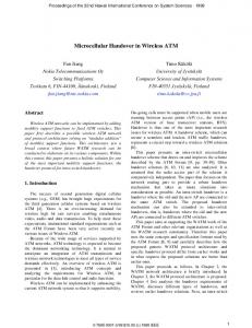
3.3. SPMIPv6 overview In our description of SPMIPv6, we use the same terminology as used in PMIPv6 and nodes (MN, MAG-old and MAG-new and LMA). A typical message sequence diagram of SPMIPv6 is shown in Figure 2. The protocol relies on two triggers: trigger-1, which marks the prediction of a possible handover and trigger-2, which indicates breaking the connection between the MN and MAG-old. MAG old, as handover coordinator, initiates trigger-1 based on information collected from various resources such as the MN, old Access Point (AP), etc. Then MAG-old sends trigger-1 to the MN using for example an IEEE802.21 Media Independent Command Service (MICS) [24]. Both MN and MAG-old can detect trigger-2, specification of which is out of our scope. MAG old
MN
MAG new
LMA
data -plane trigger-1 L2 setup to the new network
trigger-1 SPBU
PBU (s = 1, …) start bi-casting
SPBA
PBA
trigger-2 RS RA
PBU stop bi-casting PBA
Figure 2: A typical SPMIPv6 message sequence diagram. When receiving trigger-1, the MN starts to establish L2 connectivity with the target network. The required information about the target network is included in trigger-1 message. Whenever the MN loses its ongoing L3 connection to the serving network, i.e., the MN detects trigger-2, the MN sends a RS message to the target network similarly to PMIPv6. The Finite State Machine (FSM) in Figure 3 describes the operations of MAG-old. Each edge of the finite state machines is labeled with the input and output message(s) in the nominator and denominator of the label, respectively. After detecting trigger-1, MAG-
old sends a trigger-1 message to the MN and a Simultaneous PBU (SPBU) to MAG-new that includes the MN’s ID and a timeout value. In handover initiated state MAG-old waits for the acknowledgement of SPBU, i.e., the SPBA, and/or trigger-2 that brings MAG-old into the idle state. If trigger-2 does not arrive, i.e., when the MN does not move from the serving MAG-old, the timer expires and the MAG-old returns to the origin “connected” state. connected (forward !")
trigger-2 -
events/info send trigger-1 send SPBU set the timer
timeout
handover initiated (forward !")
SPBA -
idle
-
trigger-2 -
Figure 3: The FSM of MAG-old operation. Similarly, the FSM in Figure 4 describes the operations of MAG-new. After receiving the SPBU, MAG-new sends a PBU to the LMA with a simultaneous binding flag on (i.e., s=1). The s flag being 1 or 0 indicates to the LMA to bi-cast or unicast, respectively. After receiving the PBA from the LMA, MAG-new buffers IP packets destined to the MN as long as the MN is not attached to MAG-new. The buffer size at MAG-new is limited. If it is full, the earliest packets received are dropped. Anytime when the MN attaches to the new link it sends a RS to MAGnew. Receiving RS, MAG-new sends a PBU with s=0 to the LMA to stop bi-casting. The left branches in Figure 4 (between states idle, waiting and connected) indicate the case where SPMIPv6 operates the same way as PMIPv6. RS
waiting for PBA RS PBA
PBU (s=0) SPBA
RA RS
connected (forward !")
idle
PBU (s=0)
PBU (s=0) RA
handover initiated
SPBU PBU (s=1)
PBA SPBA set the timer
buffering (")
timeout -
Figure 4: The FSM of MAG-new operation.
When the LMA receives a PBU message, the LMA updates its binding table entry of the MN with the CoA of the MAG sending the PBU, i.e., the MAG-new. The LMA also responds with the PBA to the MAG-new, which includes the IP address prefix of the MN. If the s flag of PBU is 1, then the LMA starts bi-casting downstream data packets to both MAG-new and MAG-old. If the flag is 0, the LMA stops sending the downstream data packets to the MAG-old and removes the MAG-old state from its binding table for the MN. If the LMA starts bi-casting data packets to both MAGs, but it does not receive any PBU with s=0 from the MAG-new for a period of time, i.e., after a timer expires, the LMA stops sending downstream packets to the MAG-new and removes the MAG-new state from its binding table for the MN.
4. Performance analysis We analyze the performance of SPMIPv6 with two performance measures: handover latency and packet loss latency for downstream data flows (from the Correspondent Node (CN) to the MN). Handover latency measures the maximum time interval in which the MN does not receive any IP packet due to handover. Usually this handover latency is marked by the moment that the MN receives the last IP packet from the MAG-old, and the moment that the MN receives the first IP packet from the MAG-new. Packet loss measures the number of downstream packets lost at the MN during the handover period. These packets may be discarded by various network elements due to buffer overflow, connection loss, etc. If the application level throughput remains the same during the handover, the packet loss can be mapped onto a period called packet loss latency, given that data throughput.
4.1. Notation Let THO and TPL denote the handover latency and packet loss latency, respectively. These performance measures will be expressed as a function of a number of network parameters as follows. We designate • the Round Trip Time (RTT) between a MAG and the LMA by RTTMAG-LMA, • the RTT between a MN and a MAG connected to it by RTTMN-MAG, and • the RTT between two neighboring MAGs by RTTMAG-MAG. In our analysis we assume the same signal propagation time in upstream and downstream directions. The model we use to evaluate the handover latency and packet loss latency is an elementary one. We basically sum the delay components involved in
the handover, assume the individual delay components to be fixed, and assume the same throughput and MNMAG, MAG-MAG, and MAG-LMA delays for the serving and target networks. Let’s parameters tr1 and tr2 denote the moments that trigger-1 is issued at MAG-old and the moment that trigger-2 is detected at the MN, respectively. Our notation rule used in this paper is: tX denotes the moment that event X occurs and capital TX = tX ! tr1 denotes its time difference with moment tr1. We define the prediction time by D = tr2 ! tr1, which is the time that elapses between prediction of a handover and the (forced) disconnection of the MN from the old link. Let D2 denote the duration of the L2 connection setup process (for authentication, L2 association, etc) to the new network link and tD2 mark its end moment. In SPMIPv6 we have assumed that the MN initiates the new L2 setup after receiving trigger-1 (in Section 4.4 we will relax this condition), then:
TD 2 = t D 2 − tr1 = 0.5 RTT MN − MAG + D2 (1) Further, we assume that trigger-2 follows the event of trigger-1 being received at the MN, i.e.:
D = tr2 − tr1 ≥ 0.5 RTT MN − MAG (2) If tr2 arrives in period [tr1 , tr1 + 0.5RTTMN-MAG], then one can show that SPMIPv6 and PMIPv6 performances are the same (but we don not intend to go into details).
4.2. Handover latency Let’s first consider a basic handover scenario where trigger-2 occurs after the L2 connection setup (i.e., tr2 > tD2). In order to define the corresponding handover latency we use three auxiliary parameters tA , tB and tC that mark three time events at MAG-new as shown in Figure 5:
t A = tr1 + 0.5RTTMAG − MAG t B = tr1 + 0.5RTTMAG − MAG + RTTMAG − LMA t C = tr2 + 0.5RTTMN − MAG = tr1 + D + 0.5RTTMN − MAG
MAG old
MN tr1
THOb
LMA
MAG new
THO 0.5RTTMN-MAG
SPBU
H
tA
H
PBU
D2
a
tD2
tr2
TL
tC
H c
The handover latency of the basic handover scenario is called “basic handover latency” and b
denoted by THO . The basic handover latency is defined in relation (3) with respect to the position of tC (thus b
tr2) relative to tB and tA (thus, THO depends on prediction time D). The last row in (3) follows from (2) and expresses the fact that SPMIPv6 acts like PMIPv6 when tC < tA.. tC ≥ t B tB > tC ≥ t A
(3)
t A > tC ≥ tr1 + RTTMN − MAG
To simply the notation in (3), let’s define TL, TH, L, and H as follows: TL = 0.5( RTT MAG − MAG − RTTMN − MAG )
(4)
D ≥ TH $L ! b T HO ( D ) = #H − ( D − TL ) T H > D ≥ TL !H T L > D ≥ 0.5 RTT MN −MAG " b
L TL
TD2 TH
(5)
In Figure 6-(a), THO is depicted as a function of D. When D is below the threshold TL, the handover delay is at a high level, H. When D is above a certain threshold TH, the handover delay is at a low level, L. Between these two thresholds, the handover delay linearly decreases from H to L.
L
d D
TL
TH TD2
Figure 6: Handover latency: basic form (a) and for three ranges of D2, i.e., TD2 0, we first consider the basic packet loss
TPLb
b PL
latency T ( D, k ) which holds if trigger-2 arrives after establishing the new L2 connection (i.e. TD2 < D). To derive the basic packet loss latency, we first derive it for k=". In this case, the packet loss period starts when the first packet arrives at MAG-old that is not sent to the MN (i.e., moment ts=tr2-0.5RTTMN-MAG). The packet loss period ends when the first packet arrives at MAG-new that is (later) sent to the MN (i.e., moment te). There are two possibilities:
$tr + 0.5 RTT MN − MAG + RTTMAG − LMA D < TL te = # 2 tB D ≥ TL " Above, we calculated the packet loss period at MAGs. Because both MAGs are the same distance from the MN, the resulting latency holds also for the MN. Thus: b TLO ( D, ∞ ) = t e − t s =
D < TL D ≥ TL
Relation (8) indicates that the packet loss is negative if D < 0.5(RTTMAG-MN+RTTMN-MAG) + RTTMAGLMA. In practice this means that the MN receives twice the packets bi-cast by the LMA. Note that the process of bi-casting does not continue for ever, and stops at moment tC + RTTMAG-LMA at MAG-new. The buffering process at MAG-new starts at tB and ends at tC. Thus, the maximum length of buffering at MAG-new is: (9)
b Now let’s consider TPL ( D, k ) for finite values of k. If D