REDUCING MULTIPLE MODES OF VIBRATION BY DIGITAL FILTERING AND INPUT SHAPING
Joshua Vaughan and William Singhose Woodruff School of Mechanical Engineering Georgia Institute of Technology Atlanta, Georgia USA
[email protected]
ABSTRACT The residual vibration of flexible systems can be reduced by properly shaping the reference command. There has been substantial evidence presented that input shaping is better than notch filtering for shaping reference commands to suppress vibration in mechanical systems. Much of this evidence is empirical comparisons between traditional filters and robust input shapers. Recently, a proof showing that notch filters are always equal to or longer in duration than an input shaper with identical single-mode vibration suppression constraints was presented. This paper expands on that previous result by extending the proof to multi-mode systems. The important ramification of this proof is that multi-mode input shapers suppress vibration more quickly than multi-mode notch filters. Ease of design, computation, and implementation are also discussed. Simulations of an industrial bridge crane demonstrate the key differences between the two methods.
A3
p(t)
*
0
Baseline Command
i(t)
A1
A5 t2
0
t3
A2
t4
t5
A4
Filter/Shaper
u(t)
0 t2 t3 t4 t5
Shaped Command Fig 1. SHAPING A REFERENCE COMMAND.
INTRODUCTION The reference command signals used to drive flexible systems can significantly impact performance. Digital filtering and input shaping are well-known methods for shaping the reference commands to reduce vibration. Since the development of robust input shaping [1, 2], researchers have produced substantial evidence that input shaping is superior to notch and lowpass filtering for applications involving flexible mechanical systems with one or two dominant modes [1, 3–5]. Much of this evidence has been empirical comparisons between traditional notch filters (Chebychev, elliptical, Parks-McClellan, etc.) and robust input shapers (ZVD, EI, SI, etc.). Nonetheless, many researchers still promote traditional filtering methods for control of mechanical
vibration [6–9]. Recently, however, a proof was presented that showed notch and lowpass filters can never be shorter in duration than an input shaper with the same vibration-suppression constraints [10]. The ramification of this proof is that input shaping enables faster responses than traditional filters. Digital finite impulse response (FIR) filters and input shapers are both sequences of impulses that are convolved with a baseline command to produce a shaped reference command. This process is shown in Fig. 1. If the filter or shaper is designed correctly, then the shaped command will move the system without significant residual vibration. The key difference between the two command-shaping methods lies in the constraint equa-
1
|I(0)|=1 Vtol !P1 !S1
!P2 !S2
!P3 !S3
!S4
!P4
Fig 2. MULTI-MODE NOTCH FILTER CONSTRAINTS. tions that are used to design the impulse sequences. Notch filters pass certain frequencies with very little attenuation or amplification (passbands), as shown graphically in Fig. 2. The figure shows the magnitude of the notch filter’s Laplace transform on the vertical axis and frequency on the horizontal axis. Notch filters also suppress a range or ranges of frequencies (stopbands). The magnitude variation within the passbands determines how accurately the frequency amplitudes are passed through the filter. In the stopband frequency ranges, the filter is required to have a small magnitude Laplace transform. This requirement attenuates these frequencies when the filter is used to shape a command signal going into a flexible system [2, 11–15]. The height of the stopband range determines how much these frequencies are suppressed. For mechanical systems, this height is the tolerable vibration limit, Vtol . Between the passbands and stopbands are transition bands. In these frequency ranges, no requirements are placed on the filter. Input shapers are designed by requiring them to suppress a range of frequencies (stopbands). There are no passband requirements, but the magnitude of the Laplace transform must equal one at zero frequency. This constraint is not explicitly enforced as a passband constraint, but rather it is achieved by requiring the impulse amplitudes to sum to one. This constraint is also enforced for notch filters and ensures that the steady-state gain of the filtering process equals one. When this condition is satisfied, the filtered command signal reaches the same steady-state value as the baseline reference command that is being shaped. Note that this constraint is not explicitly stated in some filter design algorithms and is typically solved for in an iterative fashion [6]. When designing filters or input shapers there are many performance measures that can be considered. For example, the wider the stopband, the more robust the command shaping will be to uncertainties in the vibration frequency that is being targeted for suppression. However, as the stopband width is increased, the duration of the filter or shaper must increase (assuming all other constraints are held constant) [16, 17]. When the filter or shaper duration increases, the command rise time increases, which in turn, slows down the system rise time. If the tolerable vibration limit is lowered, then the command shaping
will suppress the vibration to a greater extent. Lowering the vibration limit will also increase the duration of the filter or shaper. Given that performance requirements can vary from system to system, this paper focuses on the two most important requirements: vibration suppression and rise time. This paper will expand upon the proof presented in [10] to show that for any given vibration suppression requirements and selection of the minimum duration solution, multi-mode notch filters can never be faster than multi-mode input shapers. Although this paper concentrates on proving input shaper superiority in this fundamental design trade-off, it also shows that input shapers are superior in ease of design and implementation. Note that this paper does not claim that input shapers are superior to filters for all applications; it only seeks to prove that input shapers are superior to filters for vibration reduction via command shaping in mechanical systems with a few dominant modes. The next section describes the design criteria for filters and input shapers. It is then proven that filters cannot be shorter in duration than input shapers with identical multi-mode vibration suppression constraints, given selection of the minimum time solution. The results of the proof are then expanded upon through an example performance comparison and discussion of ease of design, computation, and implementation.
DESIGN CRITERIA Multi-Mode Notch Filter Constraints The frequency-domain constraints needed to design a twomode notch filter are shown graphically in Fig. 2. The figure shows that at frequencies below ωP1 , at frequencies between ωP2 and ωP3 , and at frequencies above ωP4 the filter maintains amplitudes near one. That is, these frequencies are passed without significant amplitude modification. The height of the magnitude variation (shown as grey areas) determines how accurately the frequency amplitudes are passed through the filter. In the stopband frequency ranges, between ωS1 and ωS2 and between ωS3 and ωS4 , the filter is required to have a small magnitude Laplace transform. This requirement attenuates these frequencies [2, 11–15, 18]. The height of the stopband range determines how much these frequencies are suppressed. For mechanical systems, this height is the tolerable vibration limit, Vtol . An additional requirement is that the magnitude of the Laplace transform must equal one at the zero frequency. This ensures that the steady-state gain of the filtering process equals one. If a filter meets the constraints shown in Fig. 2, then when it is used to shape the baseline reference command, a system driven by the filtered command will have low vibration at frequencies in the two stopbands. There are numerous possible methods for designing a filter to meet the specifications [6,19–22]. However, irrespective of the method, the filter must satisfy constraints on the passbands and on the stopbands. These constraints can be visualized by placing constraints at numerous discrete frequencies. For example, Fig. 3 shows a stopband with constraints indicated by circles at several
I(!i) !1+"1U I(! i) !Vtol 1
|I(0)|=1
Vtol !S1
I(!i) "1-"1L
!P1
!S2
Fig 3. DISCRETE FREQUENCY STOPBAND CONSTRAINTS.
Fig 4. DISCRETE FREQUENCY PASSBAND CONSTRAINTS.
frequencies. At each labeled frequency, the design constraints limit the magnitude. Given that the notch filter is a sequence of impulses, the normalized vibration amplitude it induces at a frequency, ωn , with an associated damping ratio of ζ is given by:
where m is finite. The design constraints given above are only one way to enforce the stopband requirements. This approach is used to illustrate the idea of constraint equations because it is straightforward. Many other approaches exist and they can lower the number of constraints by, for example, limiting the vibration at only the peak values of the filter’s Laplace magnitude plot within the stop band [16]. So, a more general statement of the stopband constraints shown in Fig. 2 is:
V (ωn , ζ) = e−ζωn tN
q [C (ωn , ζ)]2 + [S (ωn , ζ)]2
(1)
where, C (ωn , ζ) = ∑Nj=1 A j eζωn t j cos (ωd t j )
(2)
S (ωn , ζ) = ∑Nj=1 A j eζωn t j sin (ωd t j )
(3)
A j and t j are the amplitudes and time locations of the N impulses that compose the filter [2]. Therefore, to suppress the vibration to below the tolerable level at a frequency of ωn , the notch filter impulses must satisfy the following equation: V (ωn , ζ) ≤ Vtol
(4)
To suppress the vibration over an entire stopband range, the design constraints must include multiple versions of the above equation, each enforced at a different frequency. As the number of suppressed frequencies approaches infinity, the constraints ensure that every frequency within the stopband is suppressed. This theoretically-possible set of constraints on a stopband can be stated as: SBT : V (ωi , ζ) ≤ Vtol ,
i = 1, 2, . . . , ∞
(5)
where the frequencies, ωi , range from the low end of the stopband to the high end. Of course an infinity of equations cannot actually be used, but it has been shown that just a few such constraints will effectively limit the vibration [16]. Therefore, the design constraints in the above equation can be replaced with the practically-achievable set of constraints given by:
SB1 : V (ωi , ζ) ≤ Vtol ,
ωS1 ≤ ωi ≤ ωS2
(7)
SB2 : V (ωi , ζ) ≤ Vtol ,
ωS3 ≤ ωi ≤ ωS4
(8)
The exact method for formulating and solving the constraints in (7) and (8) is not important for the purposes of this paper. What is important to understand is that a set of constraint equations must be enforced to limit vibration in the stopbands. The design requirements for the passbands are more complicated. Figure 4 shows the requirements for the low-frequency passband that runs from 0 to ωP1 . Again, discrete constraints are used to illustrate the requirements. The passband has constraints that limit the maximum value of the magnitude, just as in the stopband. The passband also has constraints that require the magnitude of the Laplace transform to be above a certain level. Again, these constraints are shown at a finite number of frequencies in Fig. 4. A general expression for the constraints on the magnitude in the passbands is: PB1 : 1 − ε1L ≤ V (ωi , ζ) ≤ 1 + ε1U ,
0 ≤ ωi ≤ ωP1
(9)
where ε1U and ε1L are some small values. The passbands between the two stopbands and at the higher frequencies in Fig. 2 require constraints similar to those at the lower frequencies: PB2 : 1 − ε2L ≤ V (ωi , ζ) ≤ 1 + ε2U , ωP2 ≤ ωi ≤ ωP3 (10)
SBP : V (ωi , ζ) ≤ Vtol ,
i = 1, 2, . . . , m
(6)
PB3 : 1 − ε3L ≤ V (ωi , ζ) ≤ 1 + ε3U , ωP4 ≤ ωi
(11)
To ensure unity gain of the filtering process, the Laplace transform magnitude at the zero frequency must equal one. This is equivalent to requiring the impulse amplitudes to sum to one: SS1 : ∑ A j = 1
|I(0)|=1
(12)
Note again that this constraint is not explicitly included in many filter design methods, but must be enforced for mechanical systems to ensure the system is moved to the same final state as with the unfiltered command. The entire set of vibration constraints for a typical two-mode notch filter can now be stated as:
Vtol !S1
!S2
!S3
!S4
Fig 5. MULTI-MODE INPUT SHAPER CONSTRAINTS. V IBNF2 : {SB1, SB2, PB1, PB2, PB3, SS1}
(13)
As the number of vibratory modes and intervening passbands increase, so do the number of constraints. For a system with k suppressed modes, there will be 2k + 2 constraints: V IBNFk : {SB1, . . . , SBk, PB1, . . . , PB(k + 1), SS1}
of the minimum-duration solution, a multi-mode notch filter can never be shorter in duration than a multi-mode input shaper. Proof: The set of constraints needed to design a notch filer to suppress k-modes of vibration is:
(14) V IBNFk : {SB1, . . . , SBk, PB1, . . . , PB(k + 1), SS1}
Multi-Mode Input Shaper Constraints The constraints needed for a two-mode input shaper are shown graphically in Fig. 5. The constraint set consists of two stopband constraints:
For a multi-mode input shaper that suppresses k-modes of vibration, the constraint set is: V IBISk : {SB1, . . . , SBk, SS1}
SB1 : V (ωi , ζ) ≤ Vtol ,
ωS1 ≤ ωi ≤ ωS2
(15)
SB2 : V (ωi , ζ) ≤ Vtol ,
ωS3 ≤ ωi ≤ ωS4
(16)
and the unity-gain constraint: SS1 : ∑ A j = 1
(17)
The entire set of constraints for a two-mode input shaper is then: V IBIS2 : {SB1, SB2, SS1}
(18)
(20)
(21)
The constraint set for the input shaper, (21), is a necessary subset of the constraint set for the notch filter, (20). Therefore, any solution that satisfies the multi-mode notch-filter constraints also satisfies the input-shaper constraints. This means that the set of possible multi-mode input-shaper solutions is equal to or larger than the set of possible multi-mode notch-filter solutions. Given that the filtered/shaped command duration will be increased by the duration of the filter or shaper used, the minimum duration solution should be selected. This selection process is captured by minimizing the time of the last impulse of the filter or shaper:
To suppress k modes of vibration, k + 1 constraints are required:
min(tN )
V IBISk : {SB1, . . . , SBk, SS1}
(19)
Using this selection criterion, a multi-mode notch filter can never be shorter in duration than a multi-mode input shaper that satisfies the same vibration suppression constraints. QED.
PROOF OF INPUT SHAPER SUPERIORITY FOR MULTIMODE SYSTEMS Theorem: The set of multi-mode notch-filter solutions is a subset of the set of multi-mode input-shaper solutions. Therefore, for a given set of vibration-suppression constraints and selection
Implications: While the proof guarantees that notch filters cannot be shorter in duration than an input shaper with identical stopband and selection requirements, it is easy to see that input shapers have significantly fewer requirements to satisfy. Therefore, in many practical design scenarios, the input shaper can be
(22)
significantly shorter than the corresponding filter. In fact, the only way to get a notch filter that has performance close to an input shaper is to shrink the passbands down to zero frequency width (i.e. removing them). But this, of course, means that we are designing an input shaper rather than a notch filter.
1.4 Magnitude, |I(s)|
Payload
Fig 7. INDUSTRIAL BRIDGE CRANE WITH DOULBE-PENDULUM PAYLOAD
1.5 1 0.5 0 0
Unshaped Notch Filtered SI Shaped 5
Time (s)
10
15
Fig 8. EXAMPLE BRIDGE CRANE PAYLOAD RESPONSES. suppress the vibration that occurs if the payload configuration creates frequencies in the suppressed ranges, as shown in Fig. 8. However, as seen in Fig. 9, the shaped command is much shorter in duration, leading to the faster response shown in Fig. 8.
Notch Filter SI Shaper
1.2
Hook
Payload Position (m)
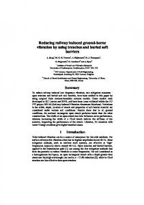
FILTER PERFORMANCE COMPARISON The proof in the previous section demonstrated that filters can never provide vibration suppression faster than input shapers. However, it does not indicate how much better input shapers perform. This section presents one example that demonstrates the degree of input shaper superiority in terms of rise time. The magnitude plot of a two-mode notch filter is shown in Fig. 6. The filter was designed to suppress modes near 0.22Hz and 1.13Hz, with robustness to ±10% changes in frequency around each mode. The tolerable level of vibration was 5% and the passband was constrained to be between 0.95 and 1.05. The low-passband edge was 0.05 Hz, the mid-passband between 0.4 and 0.8 Hz, and the high-passband edge at 1.4Hz. The sampling frequency was 20Hz. The gray-shaded areas on the figure show the passbands. Also shown in the figure is the magnitude plot for a twomode Specified Insensitivity (SI) shaper [23, 24]. The two-mode notch filter and the two-mode SI shaper in the figure were designed to suppress vibration over the same frequency ranges. However, the SI shaper is 30% shorter in duration than the notch filter (4.52s compared to 6.25s). The extra passband constraints of the notch filter force it to be longer than the SI shaper. For many applications these additional constraints, and the resulting cost in command duration, provide no additional benefit. This is especially true of point-to-point motion of a flexible, mechanical system, where command duration dictates the speed of motion, not what frequencies are passed by the command shaping. For example, consider an industrial bridge crane with a double-pendulum payload like the one shown in Figure 7 [24, 25]. The notch filter and SI shaper shown in Fig. 6 will both
Trolley
1 0.8 0.6 0.4 0.2 00
Vtol 0.5
1
1.5
Frequency (Hz)
2
Fig 6. COMPARISON OF TWO-MODE NOTCH FILTERS AND SI SHAPERS.
EASE OF SOLUTION AND IMPLEMENTATION Given that digital filters and input shapers are implemented in the same manner and their constraint sets are similar, it might seem that the ease of solution and implementation would be similar. However, there are two important aspects to consider i) ease of generating the impulse sequence and ii) implementation of the solution. Filters must satisfy the input-shaper constraints equations, plus some additional constraints. Therefore, they must be more difficult to generate in a computational sense. In addition, an
Trolley Velocity (m/s)
0.4
Unshaped Notch Filtered SI Shaped
0.3 0.2 0.1 0
-0.1 0
5
Time (s)
10
15
Fig 9. EXAMPLE BRIDGE CRANE TROLLEY VELOCITY COMMANDS. engineer designing a filter must also choose more design parameters than when designing an input shaper. This is illustrated by the size of the constraint sets in (20) and (21). An additional benefit from the lower number of constraints is the ability to solve for impulse amplitudes and times in closed-form. In fact, there are closed-form solutions for many input shapers [2,17,26], including some addressing additional constraints such as fuel use [27]. No such closed-form solutions exist for digital notch filters [20, 21]. An additional consideration is the implementation of the filters on real machines. Filters designed using traditional filtering techniques, originally developed for signal processing, do not include any form of actuator constraints. As such, commands shaped with these filters may not be realizable on a given system. Input shapers can easily contain constraints that create realizable commands. For example, shaper impulse amplitudes can be limited to be positive or explicitly bounded to create commands within the actuator limits of the unshaped command [17, 28, 29]. The larger number of impulses that comprise notch and lowpass filters can also create implementation difficulties. As the number of impulses increases, so does the likelihood that a nonimplementable command change will occur. Because they contain fewer impulses, input shapers generally create simpler commands than notch filters. As a result, actuators are more likely to be able to track an input-shaped command than a filtered command. This is demonstrated by the commands in Fig. 9; the notch-filter command contains more aggressive velocity transitions than the SI-shaped command. The lower computational cost of implementing an input shaper also means that an input-shaped command is more likely to be realizable on a given system than a notch-filtered command. For example, input shaping has been implemented on a micro-mill with a closed-architecture CNC controller [30]. Despite little access to trajectory-generation parameters and a sampling period close to the vibration period of the system, input shaping successfully reduced positioning stage oscillation. Other researchers have shown that input shaping can be successfully implemented on low-powered microcontrollers and tailored to
meet the requirements of low-resolution Pulse-Width-Modulated (PWM) commands while maintaining low vibration [31].
CONCLUSION The constraints used to design multi-mode notch filters and multi-mode input shapers were categorized and compared. It was shown that input shapers need to satisfy fewer constraints than notch filters. As a result, the input-shaper solution space is larger and includes the solution space of the notch filters. Therefore, multi-mode filters can never be shorter in duration than a multi-mode input shaper with identical vibration-suppression constraints. In addition, input shapers were shown to be easier to design, compute, and implement. Simulations of an industrial bridge crane demonstrated some of the key advantages of input shaping.
ACKNOWLEDGEMENTS The authors would like to thank Boeing Research and Technology and the Japan Society for the Promotion of Science (JSPS) for their support of this work.
REFERENCES [1] Singer, N. C., and Seering, W. P., 1989. “Design and comparison of command shaping methods for controlling residual vibration”. In IEEE International Conference on Robotics and Automation, Vol. 2, pp. 888 – 893. [2] Singer, N. C., and Seering, W. P., 1990. “Preshaping command inputs to reduce system vibration”. Journal of Dynamic Systems, Measurement, and Control, 112, March, pp. 76–82. [3] Singer, N. C., 1989. “Residual vibration reduction in computer controlled machines”. PhD thesis, Massachusetts Institute of Technology. [4] Singer, N. C., Singhose, W. E., and Seering, W. P., 1999. “Comparison of filtering methods for reducing residual vibration”. European Journal of Control(5), pp. 208–218. [5] Ahmad, M., Ismail, R. R., Ramli, M., Nasir, A., and Hambali, N., 2009. “Feed-forward techniques for sway suppression in a double-pendulum-type overhead crane”. In International Conference on Computer Technology and Development, pp. 173–178. [6] Economou, D., Mavroidis, C., Antoniadis, I., and Lee, C., 2002. “Maximally robust input preconditioning for residual vibration suppression using low-pass fir digital filters”. Journal of Dynamic Systems, Measurement, and Control, 124(1), pp. 85 – 97. [7] Glossiotis, G., and Antoniadis, I., 2003. “Payload sway suppression in rotary cranes by digital filtering of the commanded inputs.”. Proceedings of the Institution of Mechanical Engineers – Part K – Journal of Multi-body Dynamics, 217(2), pp. 99 – 109.
[8] Economou, D., Mavroidis, C., and Antoniadis, I., 2004. “Robust vibration suppression in flexible systems using infinite impulse response digital filters”. Journal of Guidance, Control, and Dynamics, 27(1), pp. 107 – 117. Vibration suppression;Robustness-error-delay (RED) curves;. [9] Glossiotis, G., and Antoniadis, I., 2007. “Digital filter based motion command preconditioning of time varying suspended loads in boom cranes for sway suppression”. J. Vib. Control, 13(5), May, pp. 617 – 56. [10] Vaughan, J., and Singhose, W., 2008. “Comparison of command filterting methods for vibration reduction in automated manufacturing”. In International Symposium on Flexible Automation. [11] Bhat, S. P., and Miu, D. K., 1990. “Precise point-topoint positioning control of flexible structures”. Journal of Dynamic Systems, Measurement, and Control, 112(4), pp. 667–674. [12] Singh, T., and Vadali, S. R., 1993. “Robust time-delay control”. Journal of Dynamic Systems, Measurement, and Control, 115, pp. 303–6. [13] Meckl, P. H., and Kinceler, R., 1994. “Robust motion control of flexible systems using feedforward forcing functions”. IEEE Transactions on Control Systems Technology, 2(3), pp. 245 – 254. [14] Shiller, Z., and Chang, H., 1995. “Trajectory preshaping for high-speed articulated systems”. Journal of Dynamic Systems, Measurement and Control, 117(3), pp. 304 – 310. [15] Feddema, J. T., Dohrmann, C. R., Parker, G. G., Robinett, R. D., Romero, V. J., and Schmitt, D. J., 1997. “Control for slosh-free motion of an open container”. IEEE Control Systems Magazine, 17(1), pp. 29 – 36. [16] Singhose, W., Seering, W., and Singer, N., 1996. “Input shaping for vibration reduction with specified insensitivity to modeling errors”. In Japan-USA Sym. on Flexible Automation, Vol. 1, pp. 307–13. [17] Vaughan, J., Yano, A., and Singhose, W., 2008. “Comparison of robust input shapers”. Journal of Sound and Vibration, 315(4-5), pp. 797 – 815. [18] Murphy, B. R., and Watanabe, I., 1992. “Digital shaping filters for reducing machine vibration”. IEEE Transactions on Robotics and Automation, 8(2), pp. 285–9. [19] Parks, T. W., and McClellan, J. H., 1972. “Chebyshev approximation for nonrecursive digital filters with linear phase”. pp. 189 – 94. [20] Oppenheim, A. V., and Schafer, R. W., 1975. Digital Signal Processing. Prentice Hall, Inc., Englewood Cliffs, NJ. [21] Taylor, F. J., 1983. Digital Filter Design Handbook. M. Dekker, New York. [22] Parks, T., and Burus, C., 1987. Digital Filter Design. John Wiley & Sons, Inc., New York. [23] Singhose, W., Crain, E., and Seering, W., 1997. “Convolved and simultaneous two-mode input shapers”. IEE Control Theory and Applications, 144, November, pp. 515– 520.
[24] Singhose, W., Kim, D., and Kenison, M., 2008. “Input shaping control of double-pendulum bridge crane oscillations”. Journal of Dynamic Systems, Measurement, and Control, 130(3), May, pp. 1 – 7. [25] Kim, D., and Singhose, W., 2010. “Performance studies of human operators driving double-pendulum bridge cranes”. Control Engineering Practice, 18(6), pp. 567 – 576. [26] Singhose, W., Seering, W., and Singer, N., 1994. “Residual vibration reduction using vector diagrams to generate shaped inputs”. ASME J. of Mechanical Design, 116, June, pp. 654–659. [27] Singhose, W., Biediger, E., Okada, H., and Matunaga, S., 2006. “Closed-form specified-fuel commands for on-off thrusters”. AIAA J.of Guidance, Control, and Dynamics, 29, pp. 606–11. [28] Singhose, W., Biediger, E., Chen, Y.-H., and Mills, B., 2004. “Reference command shaping using specifiednegative-amplitude input shapers for vibration reduction”. ASME J. of Dynamic Systems, Measurement, and Controls, 126, March, pp. 210–214. [29] Vaughan, J., Yano, A., and Singhose, W., 2009. “Robust negative input shapers for vibration suppression”. Journal of Dynamic Systems, Measurement, and Control, 131(3), p. 031014. [30] Fortgang, J., Marquez, J., and Singhose, W., 2004. “Application of command shaping on micro-mills”. In 2004 Japan-USA Flexible Symposium on Automation. [31] Pel´aez, G., and Singhose, W., 2002. “Implementation of input shaping on flexible machines with integer controllers”. In IFAC World Congress on Automatic Control.