Interpolation techniques for CNC manufacturing systems are either of the ...
selecte~ number of Reference-Word circular interpolation techniques that are.
Reprinted fror:n November 1982, Vol. 104, Journal of Engineering for Industry
0. Masory Research Engineer, Gould Laboratories, Rolling Meadow, Ill. 60008, Assoc. Mem. ASME
Y. Koren Goebel Professor, Department of Mechanical Engineering, Cenler for Robotics and Integrated Manufacturing, University of Michigan. Ann Arbor, Mich. 48109 Mem.ASME
Rteference-Word Circular Interpolators for CNC Systems Interpolation techniques for CNC manufacturing systems are either of the Reference-Pulse or Reference-Word type. Reference-Pulse interpolators have been discussed in a previous paper [2]. The present paper provides an analysis of a selecte~ number of Reference-Word circular interpolation techniques that are us.efu/ m CNC systems. These interpolators junction in an on-line iterative mode and generate binary words which are supplied as references to the control/oops in Sampled-Da~a CNC sys.tems. T~e various methods are evaluated in terms of accu,racy, maxzmum permztted radzus, and number of required iterations to complete a circular arc.
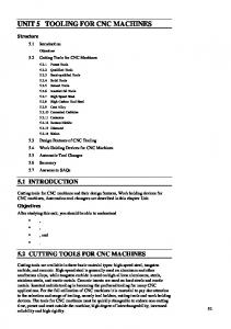
Introduction The present paper is the last in a series of three papers dealing with the design concepts of computer numerical control (CNC) systems [1, 2]. The first pape:r [1] presented two principal structures of control systems denoted as Reference-Pulse and Sampled-Data systems. With the first technique the computer produces a sequenc:e of reference pulses for each axis of motion, each pulse gene:rating a motion of one basic length-unit (BLU) of axis travel. These pulses can actuate a stepping motor in an open-loop system, or be fed as a reference to a closed-loop hardware system. With the Sampled-Data technique, the control loop is closed by software through the computer itself, as shown in Fig. 1. The control program compares a reference binary word with the feedback signal to determine the position error. The error is fed at fixed time intervals to a digital-to-analog converter (DAC), which in turn supplies a voltage proportional to the required axis velocity. Both of these techniques require distinct: interpolation routines to generate their corresponding references: pulses or binary words. The interpolator routine coordinates the motion along the machine axes, which are separately driven, to generate the required machining pa!h. The machining path is usually obtained from a combination of linear and circular segments, and accordingly the control program contains both linear and circular interpolation subroutines. Tlhe interpolator routine functions in an on-line mode and is usually written in assembly language in order to improve computing speed. Although linear interpolators can be easily written in assembly language, difficulties arise in assembly language programming of circular interpolators which necessitates the on-line solution of a second order equation. The previous paper [2] in this series was concerned with the evaluation of circular interpolators for Reference-Pulse CNC systems. All Reference-Pulse interpolators are based on an iterative technique controlled by an interrupt dock. At each Contributed by the Production E ngineering Division for publication in the JOURNAL OF ENOINEERINO FOR INDUSTRY
A single·axis sampled·data system
and presented at. the 1981 Winter
Annual Meeti ng, November 15- 17, 1981, Washington, D.C., of the AMERJCAN SOCIETY OF MECIIANICAL ENGINEERS. Revised manuscript received at ASME Headquarters June 15,1982.
400 I Vol. 104. NOVFMR FR
Fig. 1
interrupt, a single iteration of the interpolation routine is executed, which in turn can provide an output pulse that advances the corresponding machine axis by one BLU. Therefore, the maximum attainable feedrate, or axis velocity in BLUs/s, is inversely proportional to the execution time of a single iteration. It has been shown that the appropriate Reference-Pulse interpolation technique for machine tool systems is the software DDA [3], since the uniformity of the feedrate along the circular path is obtained only with this method. Using a PDP-11 as the CNC controller, an interpolation iteration time of 52 p.5 has been obtained [2], which allows a maximum velocity of 19,230 BLUs/s. A BLU might be on the order of 10 Jtm in a typical machine tool system, resulting in a maximum feedrate of about 11 m/min, which is adequate for machining applications. However, modern CNC systems employ a single axial drive motor for both idle motions and machining, and in these systems a velocity of 11 m/min is considered to be too low for idle motion. In contrast, the maximum velocity in Sampled-Data systems is not limited by the computer. In these systems the circular interpolation is based upon approximating a circle with straight line segments. For each segment the interpolator generates a reference word proportional to the local axial velocities which are transmitted to the corresponding software loop-comparators of the control axes. The present paper evaluates Reference-Word circular interpolator techniques which can be applied to manufacturing systems permitting the simultaneous operation of two axes-of-motion.
1Q.R?
The Concept of Reference-Word Interpolators In circular interpolation, the simultaneous motion of two
y
coordinates of the successive point X(i + 1), Y(i + 1) according to equation (6). The segment lengths are: DX(i)
= X(i + l) - X(i)=(A -
l)X(i)-BY(i) (7)
DY(i) = Y(i + l) - Y(i)==(A - l)Y(i) + BX(i) and the corresponding velocities are: Vx (i) = VoDX(i)IDS(i) Vy (i) = V0 DY(i)IDS(i)
(8)
where
~~UL~----------------~------~--~
Fig. 2
2 The values obtained from equation (7) are the incremental positions, and those of equation (8) are the velocities, or the reference-words, for the present segment. These values are supplied to the software control loops.
X
Definitions for the reference·worcl technique
axes generates a circular arc at a constant t:angential velocity, or feedrate, V0 • The axial velocities satisfy the following equations:
= V0
sin O(t) Vy (t) = V0 cos O(t) Vx (t)
(1)
3 Upon completion of the segment, the routine increments the coordinates X(i) and Y(l) . Since the angle a is relatively small,,the chord length DS can be approximated by its arc length Ra and the calculation of the velocities Vx and Vy can be simplified to: Vx(i) ==K DX(i) (9)
where
Vy (i) =K DY(i) O(t) =(V0 1R)t
and~
is the radius of the circular arc. The velocity components Vx and Vy are: computed by the circular interpolator and are supplied as r-eference inputs to the computer closed-loops. The circle generated in this case is actually comprised of straight line segments . At the beginning of each segment the references are supplied by the interpolator and the end of the segment is located with the aid of a feedback signal. Increasing the number of these segments improves the accuracy of the generated cilrcle, but increases the number of iterations, thus requiring mo•re computer time. The optimal number of segments is the smallest one which maintains the path error within the required limit of one BLU. Each iteration of the algorithm corresponds to an angle a, as illustrated in Fig. 2. The choice of the a:ngle a depends on the interpolation method. All of these methods employ the difference equation: cosO(i+ 1) = AcosO(i) - BsinO(i) (2) sinO(i+ 1) = AsinO(i) +Bc·osO(i) where the coefficients A and B are given by:
A=cosa
B=sina
(3)
where K = V0 / Ra. The parameter K is a constant, which is calculated only once for each circle, and consequently the reference words are actually proportional to the segment lengths. Approximation of a circle by straight line segments causes two types of errors as illustrated in Fig. 3: (a) Radial error ER, due to the truncation effects: ER (i) = R(i) - R=,lX2 [i)_.f._¥([} -R where R is the required radius. (b) Chord height error EH defined by:
EH (i) = R - R (i) cos(a/2)
(4)
The corresponding segment is terminated at the point X(i + 1), Y(i + I) which is approximated by: X(i+ 1) = R(i)cosO(i + 1) (5) Y(i + 1) = R(i) sinO(i+ 1)
Substituting equation (2) into (5) yields: X(i+ l) = AX(i) -BY(i)
(6)
Y(i+ 1) = AY(i) + BX(i)
Equation (6) is the basic relationship which permits the calculation of a successive point based on the present one. The main differences between the variious interpolation methods are in the determination of a and in approximation of the coefficients A and Bin equation (3). Once the angle a is chosen , the interpolator routine proceeds, lfor each iteration, as follows: 1 At each point X(i), Y(i) the interpolator calculates the Journal of Engineering for Industry
(II)
Equation (10) is explicitly obtained using the approximated values of A and B, which causes the truncation error in the radius. Since the algorithms use an iterative technique, this error is accumulated with time. The effect of the truncation error ER at the ith iteration can be approximated by (see Appendix 1): (12) ER(i) = i(C - l)R where
C=.JAT+lfi
and O(i+ l)=O(i) +a
(10)
Equation (12) shows how the truncation error increases with the number of iterations. The largest circular arc produced by a single instruction in NC systems is a quarter of a circle. The compatible number of iterations is: N = 1rl2a (13) Upon completing this number of steps the error ER reaches its maximum value: (14) ERmax =(7r/2a)(C-1)R By contrast, the error EH is not cumulative. Using the formula cos(a/2) =.J(l + cosa)/2 = .J(l + .Af7i
(15)
in equation (11), yields: EH(i) =R-R(i) .J(l +A)/2.
(16)
The angle a is selected so that either the error ER or EH NOVEMBER 1982, Vol. 104/401
reaches a maximum value of one BLU. In addition to the
Table 1
angle ex, the interpolator is given the coordinates of the initial
Maximum radius in IEM
n[bits]
point [X(O), Y(O)] and the required feedrate V0 • These parameters are obtained from the part-program for each circular arc. Several interpolators applying the reference-word method are now discussed and their relative features are compared.
Q
15 23 31
8 13
16
p
Rm!BLUs]
7 10 15
4095
255 32767
The actual average A which is used in equation (27) is given by:
Euler Method The Euler method is based upon a first-order Taylor series expansion to equation (3) which provides the simplest approximation: A= I
;
B=cx
(17)
The basic equations of the algorithm are obtained by substituting for A and Bin equation (7): DX(i) =
- aY(i)
DY(i) = cxX(i) (18) Substitution of equation (18) in (9) gives the required velocities: Vx(i) = -(Vo!R)Y(i) Vy (i)
=
I
2
a2
X(i) = (1 +a) Y(i)
or at angle of 8
(29)
=1rl4 and the corresponding error is: a
4
ERmax =
(30)
R
Since ER should not exceed one unit
Since the series expansion is truncated after the frrst term, the accuracy of the Euler method depends mainly on this truncation error ER rather than on the chord error EH. The maximum error is obtained by substituting equation (17) into
a=41R
(31)
The number of iterations required to produce a quarter of a circle as obtained from equation (13) is:
(14):
N = 1rRI8
ERmax =(1r/2a)(~ - 1)R
(20)
For small a, equation (20) can be approximated by: ERmax =(?r/4)aR (21) which allows for calculating the value of a. To satisfy the accuracy requirement, the maximum permitted error is one BLU and the corresponding angle is: a=4! (?rR)
(22)
Consequently, the number of iterations required to •Complete a quarter of a circle is obtained from equation (13): N =~ R/8
(23)
The improved Euler method (IEM) [3] also us.es the approximation (17) but it applies the calculated value of X(i +I) to determine the present value of Y(i + 1). With this modification, equation (6) becomes: X(i+ l)=AX(i) - BY(i)
Y(i +I) =A Y(i)
(24)
+ BX(i+ 1)
and with substitution of A and B from (17) the main equations of the (IEM) algorithm are obtained: X(i+l) = X(i)-aY(i)
(25)
Y(i+ I) = Y(i) +cxX(i+ I) The segment lengths as defined in equation (7) are: DX(i) = -a Y(i) DY(i) =cxX(i+ I)
X(i) - aY(i)
= (l-cx )Y(i) +cxX(i) 2
402/ Vol. 104, NOVEMBER 1982
2m ' 2 C!::.R
(33)
The power m is the smallest integer which satisfies equation (33) and is obtained by SHIFT operations. Thus, a complete
implementation of the IEM algorithm is achieved by basic assembler instructions, without the necessity for either a floating-point unit (FPU) or multiplication operations. In spite of the attractive features of the IEM, special care is needed to avoid introducing a new truncation error that can arise from the right-shifts used in cxX and aY. To avoid the truncation error, then-bit word is divided into two parts. One part is q bits long and stores the radius. The other part is p bits and stores the error. In the IEM, the maximum ER (of one unit) occurs at 8= 1!'14 or when l/2N iterations have been completed. Thus, the condition:
(26) -
1
2
The improvement as compared with the previous method is illustrated by deriving the explicit expression for Y(i+ 1) in the second equation of (25): Y(i+ I)
(32)
which is less than with the Euler method by a factor of 1r (see equation (23)). Although the algorithms of the Euler and Improved Euler methods are relatively simple, they cannot be implemented with basic assembler instructions such as ADD and SHIFT. The computational difficulties arise in calculating the angle a and in performing multiplications cxX and a Y. With the Euler method, part of the difficulty in calculating the angle a is with using the factor ?f (equation (22)), which is not needed with the IEM (equation (31)). The second difficulty can be overcome by expressing the angle a in powers of 2, i.e., a=2-m, thereby permitting the use of SHIFT operations rather than multiplications. In this case the angle a is calculated by: a= 2 - m s4/R or
Improved Euler Method
X(i+ I)
(28)
rather than the value of I which is used for approximation of cosa in the Euler method. Therefore, a better approximation of the coefficient A is achieved with the IEM without any additional computational effort. The error ER reaches its maximum value for particular iteration that satisfies the condition (see Appendix 2):
(19)
(V0 1R)X(i)
1
2
-[I+ (1 - a 2 )] =I- -
N=2P
(34)
guarantees that the truncation error is less than one unit. The relationship between the maximum permitted radius Rm and the word length n can be determined through the equation:
(27)
n =q+p=log2 Rm + log 2 (
~
N)
(35)
Transactions of the ASM E
Table 2 Maximum radius in Taylor method n[bits]
q 10
15
23 31
p
5 8 10
15
21
1023 32767 2097151
The error EH is equation (11) is obtained by substitution for A, which yields:
!
EH(I) =R -R (i)j1-
a 2 =R - R (i)
+ (a2 /8)R (i) (43)
Since the error caused by the truncated series (39) leads to an increased radius with each step, the maximum value of EH is obtained at the first iteration, for R ( i) = R, which yields: Fig. 3
Errors in the generated circle
(44)
Substituting for N from equation (32) gives: n =2log 2 Rm + log 2 1r- 4
(36)
A comparison of two errors in equations (42) and (44) shows that
and since Rm = 2q
ERmax = I
q=
n+ 1.2
2
(37)
Table 1 gives the maximum allowable radius in BLU's for typical length of computer words (one bit is reserved as a sign bit): In practice only the last line in Table 1 wo•uld give sufficiently large radii in CNC systems. Therefore, a double-or even triple-precision word technique will be required in the control computer. Note that since in the Euler method the number o f iterations are greater than in the IEM and the maximum error appears at the end of the arc, the equivalent formula to (37) is: q=
I
2
n-0.15
(38)
which means that the maximum permitted radius in practice is even smaller, and the Euler method is useless for CNC applications.
2
EHmax
(45)
which means that for an angle a which satisfies a 20 BLUs, which covers virtually all practical systems (e.g., if lBLU = 10J.Lm,R >0.2 mm). The number of iterations to complete a quarter of a circle is: (47) The algorithm given by equations (40) and (41) requires a determination of a and a 2 • Expressing these values in power of 2 avoids the use of floating-point unit [5]: (48)
or
Taylor Method For the Taylor method [4] the coefficients A and B in equation (3) are evaluated by the truncated series: 1 A=l- - a2
• B=a (39) 2 ' Using these values, the basic equations of the algorithm are derived. The corresponding segment lengths are obtained from equation (7):
DX(i)
I
=- -
DY(i) = - -
2 1
2
a 2 X(i) - aY(i)
(49)
Again, the power m is determined by SHIFT operations, and all multiplication instructions in the algorithm are executed in the same way. Therefore, the Taylor method can be implemented by using basic assembler instructions. The relationship between the maXimum radius and the word-length for the Taylor method is:
(40) and since R = 2q:
a 2 Y(i) + aX(i)
q=
and the velocities obtained from equation (9): Vx (i)=-(Vo!R)[
~
aX(i)+Y(i)J
Vy (i) =(V0 /R)[ -
~
aY(i) +X(i)]
(41)
The maxim um value of the error ER is calculated! according to equation (14): ERmax = : 2
'TrCi
(J1 + ! a
4
-1)R=1rRa3 ! !6
Journal o f Engineering for Industry
2
3
n+0.56
(51)
Examples illustrating the dependence of the maximum radius on the word length are given in Table 2. The last two cases in Table 2 are practical for CNC systems. In reference [4] the Taylor method algorithm was applied to a CNC system controlled by a PDP-8 computer using a tripleprecision word. Successive points along the circular arc were computed at the rate of 1.4 millisecond per point. The interpolator occupied 600 (12 bit) words of core storage.
Tustin Method (42)
The Tustin method [6] is based on an approximate NOVEMBER 1982, Vol. 104/403
Table3 Simulation results for R = 10,000 BLU's
y
Method
N
Euler IEM Taylor Tustin ITM
relationship between the derivative operators and the discrete variablez: (52) Using the Tustin approximation yields the following relations for cosa and sin a, or A and B: 1 - (a/2) 2 a A= I + (a/2)2 ; B = 1 +(a/2)2 (53) These approximations can be used to generate circular interpolation for CNC systems. Substituting these values of A and B into equations (7) and (9) gives the basic equations of the proposed algorithm:
=-
DY(i) =
2
1 l+(a/2) 2 1
[
l + (a/2) 2
a X(i) + a Y(i)] 2 .
[
~2
-
V0 Vx(I') = - R[l+(a/2)2] 0 VY ( I') = R[l +V(a/2)2]
[
[
-
X(')
Ta
Y( ')
I+
I
Y(. ] 1)
FPU
4hrR
.,?R / 8
IEM
FPU or ASL
4/R
1fRI8
Taylor
FPU orASL
.Jf1R
~.JRT2
Tustin
FPU
../SiR
~.fR/2
ITM
FPU
4/VR
.!!....{R
4
4
8
1)=4/VR
Therefore, the angle a is increased by a factor of decreasing the number of iterations to:
+X(')] I
N= .!!.... VR
ER (i) =0 (56) Since the error ER is identically zero, the angle 01 is prescribed by the error EH given in equation (16). For R (i) =R:
(62)
Vi (63)
8 Obviously the Tustin methods require considerably more calculations than the previous methods. Basic assembler instructions are insufficient to handle the routine and an FPU is a necessity.
Comparison and Discussion
R EH = R - -== .,..--.../l+(a/2)2 which can be approximated for small a by:
(57)
al
(58)
EH= -R 2
a +8 The angle a is derived by equating the error EH toO one unit:
(59)
a= .../8 /(R - 1)=.../8/ R
which is identical to equation (46).
Improved Tustin Method The Tustin method yields an ER of zero. From a practical point of view in manufacturing systems we choose the maximum error equal to one BLU . Therefore th•e method can be improved by increasing the angle a [7). From Fig. 4 the angle a is evaluated using equation (15): ~
-R-- =.../2/(1 +A)= ...Jl+ (a/2)2 = 1 +404/ Vol. '104, NOVEMBER 1982
Euler
(55)
The truncation error is found by substituting equation (53) into (12) which shows that:
-
1.500 1.652 1.428 1.681 1.405
TableS Features of reference-word interpolators Method Programming a N
a=.../16/(R -
Ta
- 1
1.500 1.652 0.633 0.681 1.662
1.008 1.002 0.988 1.016 0.999
so that the angle a is:
.
R+l
40
1.008 1.002 0.071 1.016 1.029
(54)
Y(i) +o:X(i) ']
2
56 56
Practical ERmax EHmax
Table4 Simulation results for R = 250 BLUs Type Method N EHmax ERmax 1.557 1.549 !EM FPU 99 ASL 102 1.103 1.103 IEM 0.529 0.999 Taylor FPU 9 Taylor 0.953 0.953 ASL 13
~~---------------L------~x Fig. 4 Circle generation by the Improved Tustin Method
DX(i)
12331 3928
Simulation ERmax EHmax
8
(61)
The interpolation methods requmng an FPU were simulated for R = 10000 BLU units to produce a quarter of a circle. The results are presented in Table 3, where N is the number of iterations and the errors are given in BLUs. The errors ERmax and EHmax• calculated during the simulation of the methods, are listed in the third and fourth columns of Table 3. In a real system, however, the DACs and the position counters can only use integer numbers, so the reference word must be an integer. This means that DX, DY, Vx, and Vy must be rounded off to the closest integer value which increases the error. The maximum errors ERmax and EHmax for a real system are listed in the fifth and sixth columns of Table 3. In this example, for real systems, the interpolation methods generate errors in the range of I to 2 BLUs. In order to limit the error to 1 BLU the angle a should be decreased. It can be seen that the Improved Tustin Method will generate an arc with the fewest number of iterations. In order to compare assembly language (ASL) with the floating-point unit (FPU) methods, a simulation was performed for producing a 90 degree arc with a radius of 250
units. The results shown in Table 4 indicate that for an Transactions of the ASME
algorithm programmed with assembly instructions, the Taylor method is the best. The number of iterations required to complete! the arc by this method is considerably smaller than the number needed with IEM, while the erro~rs are always within the required tolerance of one BLU. Finally, the main features of the various algorithms have been summarized in Table 5. The interpolators of Table 5 which require an FPU will require more computer storage and have reducc~d computer speed than those implemented with ASL. From Table 5 it can be seen that if an FPU is available, the Improved Tustin Method (ITM), which has been introduced in the present paper, is the favorite. This method produces a circle using the fewest iterations and guarantees the required accuracy. The computation of the parameters A and Bin equatiion (53) does not cause any difficulties since an FPU is used. If an FPU is not available, or if implementation of assembly language is preferred, then the Taylor method [4, 5] should be applied. With this method the maximum allowable radius is much larger than with the IEM (see Tables 1 and 2), and the number of iterations required to complete the arc is smaller by a factor of .JR/2.
Acknowledgment
(Al-l) where (Al-2) By successively using equation (Al-I), as the interpolation proceeds, assuming that the initial point lies on the circle [R(O) = R], one obtains: R(i) =C;R (Al-3) The radial error ER in the ith step is determined from equation (10) and equation (A1-3): ER(i) = (C; -l)R (A1-4) Since the value of C is close to 1, equation (Al-4) is approximated by: ER(i) =i(C-l)R (Al-5)
APPENDIX
2
Defining: M(i) =R(i+ 1) - R(i) = .JX'-(i +I)+ f2(i + 1) -.JX'- (i) +
The authors would like to thank Professors S. Malkin and G. Ulsoy for their helpful comments.
APPENDIX
1
Summing the squares of both sides of equation t(6) gives:
Journal of Engineering for Industry
(A2-1)
The radial error ER at the jth step is derived by summing the incremental errors M(1), or by integrating along the arcs:
References I Koren, Y., "Design of Computer Control for Manufacturing Systems," ASME JOURNAL OF ENGINEERING FOR INDUSTRY, Vol. 101, Ne>. 3, Aug. 1979, pp. 326-332. 2 Koren, Y., and Masory, 0., "Reference-Pulse Circular ltnterpolators for CNC Systems," ASME JOURNAL OF ENGINEERING fOR INDUSTRY, Vol. 103, No. I, Feb. 1981, pp. 131-136. 3 Koren, Y., "Interpolator for a CNC System," IEEE Trans. on Computers, Vol. 25, No. I, Jan. 1976, pp. 32-37. 4 Bergren, C., "A Simple Algorithm for Circular Interpolation," Control Engineering, Sept. 1971, pp. 57-59. 5 Musse, J. , Veron, M., Lepage, F., and Drapier, J., "High Performance Tool Path Interpolator for CNC System," CIRP Manufacturintg Systems, Vol. 7, No. I , 1978. (Presented in the 9th CIRP Int. Sem. on Manufacturing Systems.) 6 Cadzow, J . A., and Martens, H. R., Discrete-Time and Computer Control Systems, Chapter9, Prentice-Hall, New Jersey, 1970. 7 Koren, Y., Computer Control of Manufacturing Systems, Chapter 5, McGraw-Hill, New Y6rk, 1983.
f2 (i)
ERU) =
t
M(i)
=iM·ds
(A2-2)
i=O
The maximum error ERmax is obtained by equating the first derivative of equation (A2-2) to zero: dER
-
=M(i) =0 (A2-3) ds Namely, at R (i + 1) =R (i) Using the definition of equation (A2-1) we see that the maximum radial error occurs when (A2-4) Xl(i + 1) + f2(i +I) =X'- (i) + f2 (i) Substitution of equation (25) into (A2-4) yields (A2-5) 2[X(i) -X(i+ l)]Y(i)/a=X'-(i+ 1)+ f2 (i) Substituting for X(i + 1) from equation (24) into the left-side term of equation (A2-5) gives Y(i) =X(i + 1), or X(i) = Y(i) +aY(i) (A2-6)
NOVEMBER 1982, Vol.104/405