MERL – A MITSUBISHI ELECTRIC RESEARCH LABORATORY http://www.merl.com
Regenerator vs. Simple-Relay with Optimum Transmit Power Control for Error Propagation
Zafer Sahinoglu and Philip Orlik TR-2003-54
July 2003
Abstract We study power dissipation in relay assisted wireless transmissions. Two types of assistance are considered: simple relaying and regenerative repeater. We find minimum transmit power levels to provision the same bit error rate (BER) in both cases. The simple-relay case considers power adjustment for error propagation at the intermediate relay node. Power consumption comparisons are made and results are discussed.
This work may not be copied or reproduced in whole or in part for any commercial purpose. Permission to copy in whole or in part without payment of fee is granted for nonprofit educational and research purposes provided that all such whole or partial copies include the following: a notice that such copying is by permission of Mitsubishi Electric Research Laboratories, Inc.; an acknowledgment of the authors and individual contributions to the work; and all applicable portions of the copyright notice. Copying, reproduction, or republishing for any other purpose shall require a license with payment of fee to Mitsubishi Electric Research Laboratories, Inc. All rights reserved. c Mitsubishi Electric Research Laboratories, Inc., 2003 Copyright 201 Broadway, Cambridge, Massachusetts 02139
Publication History: 1. First printing, TR-2003-54, July 2003
Regenerator vs. Simple-Relay with Optimum Transmit Power Control for Error Propagation Zafer Sahinoglu, Member, IEEE, and Philip Orlik, Member, IEEE
Abstract— We study power dissipation in relay assisted wireless transmissions. Two types of assistance are considered: simple relaying and regenerative repeater. We find minimum transmit power levels to provision the same bit error rate (BER) in both cases. The simple-relay case considers power adjustment for error propagation at the intermediate relay node. Power consumption comparisons are made and results are discussed.
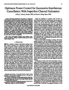
bottom), C does not perform any data recovery (e.g., error correction etc.), but cooperates with A such that A adjusts its transmit power level to provision PreAC at receiver C; and C adjusts its transmit power level to provision PreCB at receiver B. Hence, assuming that the bit errors on these two paths are additive, the total BER is constrained to PreAB .
Index Terms—Power control, error propagation, relayassisted transmission.
I
I. INTRODUCTION
sensor networks and mobile ad-hoc networks, minimizing overall power consumption in the network, and accordingly increasing network lifetime is currently an active research area. Some of the approaches to achieve power efficiency are to decrease encoder and decoder complexities, to design low power circuitries, and to develop low signalingcost routing protocols etc. There are also other techniques that try to exploit network topology to reduce power expenditure. Relay assisted transmission and power combining methods with diversity techniques [1]-[4] fall under the latter. Assume a triplet as illustrated in Fig.1. In [1], [2] and [4], it is shown that when terminal A sends its data to B through C, the overall power consumption compared to the case when A transmits directly to B is reduced. This comparison is only valid provided that two scenarios provision the same bit error rate (BER) constraint, PreAB , at destination B. In [1]-[4], this constraint is provisioned. However, their results do not take transmit power compensation due to error propagation into account at the relay node. This letter aims to fill this gap. Intermediate node C may function in two different ways: a regenerator or a simple relay. In the regenerator mode (Fig.1top), C receives data from A, at a power level that would satisfy PreAB , corrects bits in errors and forwards the N
recovered data to B at a transmit power level that would again satisfy PreAB at receiver B. In a simple relay mode (Fig.1Manuscript received February 4, 2003. The associate editor coordinating the review of this letter and approving it for publication was Dr. Yu-Dong Yao. The authors are with the Mitsubishi Electric Research Labs, Cambridge, MA 02139, USA, (phone: (617) 621 7500; fax: (617) 621 7548; e-mail:
[email protected],
[email protected] ).
Fig. 1. Illustration of the received signal power levels and bit error rates at receiving terminals in wireless transmission over (top) the regenerator (bottom) simple relay intermediate node.
II. RADIO MODEL We denote by α R , the required received signal power at rate R such that the BER is PreAB . We use a simple radio model analogous to the ones in [2] and [3] to model wireless transmission. We assume that the power consumption of a communications node, Pt (in watts), consists of power consumed by the tx/rx radio circuitry, Pcirc , which is fixed; the power consumed by the tx amplifier power, Pamp ( R ) , which is adjusted to achieve a desired BER at rate R; and power consumed to receive the bits at the receiver end, Prec ( R) . Also, different levels of clutter on propagation paths are modeled as lognormal shadowing. The shadowing effect between nodes i and j, xij (in dB), is expressed in the power equations as x /10
10 ij
(in watts).
Pt = Pcirc + Pamp ( R ) + Prec ( R )
(1) x /10
ij Pamp can be further expanded as Pamp = α R 10 ij
dijγ , where
dij is the distance between node pairs i and j, and γ is the
path loss exponent. Antenna gain is assumed to be unity. III. POWER ANALYSIS In this section, we quantify power dissipation in a communications triplet with an intermediate node that is used as a regenerator or a simple-relay (amplifier). These two cases are compared to the power consumption in direct transmission. A. Direct Transmission ij denote the amplifier power at transmitter i for Let Pamp
streaming data to receiver j. When data are directly transmitted from A to B, the total power expended in the system, Pt ' , is A AB B Pt ' = Pcirc + Pamp ( R) + Prec ( R ) + Pcirc
(2)
γ = (2Pc + Prec ( R )) + α R 10 x AB /10 d AB
In (2), we have made an assumption without loss of generality A B C that Pcirc = Pcirc = Pcirc = Pc . B. Intermediate Regenerator Node Assume that A transmits data to B using C as an intermediate regenerator node. C would consume power while both receiving data from A and forwarding it to B. Let Pt '' denote the power dissipation in this triplet. A AC C CB B Pt '' = Pcirc + Pamp ( R) + Pcirc + 2 Prec ( R ) + Pamp ( R ) + Pcirc (3) γ γ = 3Pc + 2 Prec ( R ) + α R (10 x AC /10 d AC + 10 xCB /10 dCB ) The satisfactory condition to have power savings with comparison to the direct transmission is ∆P1 = Pt " − Pt ' < 0 . ∆P1 = α R (−10
x AB /10
γ
d AB + 10
xAC /10
γ
d AC
(4) γ +10 xCB /10 dCB ) + Pc + Prec ( R ) After rearranging (4), the test condition for power savings is given in (5). γ γ 10 x AC /10 d AC + 10 xCB /10 dCB < 10 xAB /10 d γAB −
Pc + Prec ( R )
αR
(5)
C. Intermediate Simple Relay Node In this scenario, C does not perform any recovery on the data received from A. Let α RAC and α RCB denote the required received signal power levels to provision PreAC from A to C and PreCB from C to B. Then, the overall power dissipation, Pt ''' , is A AC C CB B Pt ''' = Pcirc + Pamp ( R ) + Pcirc + 2 Prec ( R ) + Pamp ( R ) + Pcirc
γ γ = 3 Pc + 2 Prec ( R ) + α RAC 10 x AC / 10 d AC + α RCB 10 xCB /10 d CB
(6)
The difference in power expenditure between simple relaying and direct transmission is ∆P2 = Pt "' − Pt ' .
γ ∆ P2 = α RAC 10 x AC / 10 d γAC + α RCB 10 xCB / 10 d CB
(7)
γ −α R 10 x AB / 10 d AB − Pc + Prec ( R )
To prove power efficiency of simple relaying compared to direct transmission ∆P2 < 0 must be satisfied. Eq.7 leads to test condition (8), which is slightly different from (5). α RAC x AC / 10 γ α CB γ 10 d AC + R 10 xCB / 10 d CB αR αR (8) Pc + Prec ( R ) x AB / 10 γ < 10 d AB − αR Note that the right sides of (5) and (8) are the same. In order to be able to compare power consumption in the intermediate simple relay scenario to either the direct transmission or to the intermediate regenerator scenario, α RCB and α RAC must be optimally selected such that the left side of (8) is minimized, under the constraint that PreAC + PreCB = PreAB . Assuming a Mary Quadrature amplitude modulation (QAM) scheme in direct transmission from A to B, PreAB can be approximated as in (9) [5]. 4(1 − 1/ M ) 3α R log 2 M (9) PreAB ≅ Q R (M − 1) N log 2 M 0 where N 0 is the power density of additive white Gaussian noise (AWGN). In a similar way, we can formulate PreAC and PreCB as in (10) and (11) respectively. PreAC ≅
4(1 − 1/ M ) 3α RAC log 2 M Q R (M − 1) N 0 log 2 M
α RAC / α R Q −1 ( 0.25β PreAB )
)
(10)
4(1 − 1/ M ) 3α RCB log 2 M Q R( M − 1) N 0 log 2 M
(11)
= (4 / β )Q PreCB ≅
= (4 / β )Q
( (
α RCB / α R Q −1 ( 0.25β PreAB )
)
where β = (log 2 M ) /(1 − 1/ M ) . The goal is to find optimum error rates * PreAC and * PreCB that would minimize objective function (12), and then to compute optimum received signal power levels *α RAC and *α RCB . Q −1 (0.25β Pr AC ) 2 e −1 10 x AC /10 d γAC AB Q (0.25β Pre ) arg min 2 PreAC Q −1 (0.25β PreCB ) xCB /10 γ 10 dCB + Q −1 (0.25β Pr AB ) e
(12)
After rearranging the derivative of (12) in terms of PreAC , we get (13). It is then straightforward to find * PreAC .
d γ 10 xAC /10 = ln Q −1 ( 0.25β (PreAB − PreAC ) ) ln AC xCB /10 γ d 10 CB
(
(
) (
+ erf −1 (1 − 0.5 β (PreAB − PreAC ) − erf −1 (1 − 0.5β PreAC ) 2
(
− ln Q −1 ( 0.25β PreAC )
)
results show that regenerating may expend up to 0.55dB less power than simple relaying, as the intermediate node gets closer to the midpoint of A-B separation, intuitively which proves to be the optimum point to achieve the highest power savings in 1-hop assisted wireless transmission.
) )
2
(13) Note that * PreCB = PreAB − * PreAC . Finally, *α RAC and *α RCB are derived from (10) and (11), and are used in (6) to compute the power dissipation in the simple relay triplet. IV. RESULTS Assume a grid area of 100x100 meters. Let us denote the Cartesian coordinates of nodes A, B and C as (0,0), (100,0) and (i,j) respectively, where i,j∈[1,99]. In order to compare relative power savings between the regenerator and the simple-relay, we define a new metric η in (14). It is the average ratio of the power expenditure in the relay mode to the power expenditure in the regenerator mode. This average is taken only over the set of coordinates where relaying has power savings, that is Pt ''' < Pt ' . The I(x) is the indicator function defined such that it returns 1 if x is TRUE, and 0 otherwise. 99
99
∑∑ ( P (i, j) / P (i, j ))Ι( P (i, j) < P ) '''
''
t
η=
'''
t
'
t
i =1 j =1
99
99
(14)
∑∑ Ι( P (i, j) < P ) '''
'
t
i =1 j =1
Fig. 2. Power savings of regenerating with respect to simple relaying at intermediate node positions over the direct path between A and B separated with 100m.
Note:
PreAB = 10−3 ,
x AB , xCB , x AC = 0 ,
M=64,
and
(3Pc + 2Prec ( R)) / α R = 0.2 .
Figure 2 plots the numerator in (14) for only intermediate node positions on the direct path between A and B. The
TABLE I AVERAGE POWER SAVING DIFFERENCE BETWEEN SIMPLERELAYING AND REGENERATING (in dB). Note: M=64
ACKNOWLEDGMENT The authors thank Dr. Anthony Vetro for helpful discussions and critical reading of the manuscript. We also thank the anonymous reviewers for helpful suggestions. REFERENCES
On the other hand, the numerical results given in Table-1 for η prove that for lower PreAB and higher γ, the performance margin between the simple relay and the regenerator gets quite narrow. Noting that results in Fig.2 and Table-1 ignore power consumption due to regeneration process at the intermediate node, simple relaying may be preferred to regenerating. For instance, assume that the relay node is located on the direct path at 70 meters from A and 30 meters from B. In Fig.2, Pt ''' < Pt '' corresponds to 0.12 (dB) for γ=4 at that position. This tells us that if the power dissipation for regeneration process exceeds 0.12 (dB), simple relaying is favored. V. CONCLUSIONS We quantify power savings performances of simple relaying and regenerating at an intermediate node in relayassisted wireless transmission. Error propagation is taken into consideration for optimizing transmit-powers.
[1] W. R. Heinzelman, A. Chandrakasan, H. Balakrishnan, “Energy-efficient Communication Protocol for Wireless Microsensor Networks,” Proc. of IEEE Hawaii Int. Conf. on System Sciences, pp. 3005-3014, January, 2000, Maui, Hawaii. [2] P. Chen, B. O’Dea, E. Callaway, “Energy Efficient System Design with Optimum Transmission Range for Wireless Ad-hoc Networks,” Proc. of IEEE Int. Conf. on Communications, ICC’02, pp. 945-952, May, 2002, New York City, New York. [3] A. Catovic, S. Tekinay, "Reducing Transmit Power and Extending Network Lifetime via User Cooperation in the Next Generation Multi-hop Wireless Networks”, J. Communications and Networks, Special Issue on Evolving from 3G deployment to 4G definition, vol. 4, no. 4, pp. 351-362, December 2002. [4] V. Rodoplu, T. H. Meng, “Minimum Energy Mobile Wireless Networks,” IEEE J. Select. Areas Commun., vol. 17, no. 8, pp.1333-1344, August 1999. [5] T. S. Rappaport, Wireless Communications: Principles and Practice, 2nd Edition, pp. 327, Upper Saddle River, NJ: Prentice Hall PTR, 2002.