1.2 Self-Tuning. A self-tuning system, illustrated in Figure 2, works on top .... The only downfall of this ..... sider the tuning system described in the previous paragraph, if the DLL .... design_compiler (A GUI Synthesis tool from Synopsis). The top ...
Remora: A Dynamic Self-Tuning Processor Chris Weaver, Fadi Gebara, Todd Austin, and Richard Brown Designed as part of EECS 627 (VLSI II) at the University of Michigan
Abstract This paper describes a self-tuning architecture that dynamically adjusts the frequency of the processor to run at the highest speed it can sustain without causing errors. This frequency is determined through dynamic verification, an online error checking technique that uses a second, simpler processor to redundantly execute instructions, detecting both design errors and transient faults.
Remora: A Dynamic Self-Tuning Processor Chris Weaver, Fadi Gebara, Todd Austin, and Richard Brown Designed as part of EECS 627 (VLSI II) at the University of Michigan hAbstract This paper describes a self-tuning architecture that dynamically adjusts the frequency of the processor to run at the highest speed it can sustain without causing errors. This frequency is determined through dynamic verification, an online error checking technique that uses a second, simpler processor to redundantly execute instructions, detecting both design errors and transient faults.
1 Introduction 1.1 Dynamic Verification To implement dynamic verification, a microprocessor is constructed using two heterogeneous internal processors that execute the same program (see Figure 1). The core processor is responsible for pre-executing the program to create the prediction stream. The prediction stream consists of all executed instructions (delivered in program order) with their input values and any memory addresses referenced. The core processor is identical in every way to the traditional complex microprocessor core up to (but not including) the retirement stage. The checker processor follows the core processor, verifying the activities of the core processor by re-executing all program computation in its wake. The high-quality stream of predictions from the core processor serves to simplify the design of the checker processor and speed its processing. Pre-execution of the program on the complex core processor eliminates all the processing hazards (e.g., branch mispredictions, cache misses, and data dependencies) that slow simple processors and necessitate complex microarchitectures. Thus it is possible to build an inorder checker without speculation that can match the retirement bandwidth of the core. In the event the core produces a bad result (e.g., due to overclocking, or a design error), the checker processor will fix the incorrect result, flush all internal state from the core processor, and restart it after the
C o re P ro c e sso r C o re P ip e lin e
L 1 ca che
CT
c o re R F
errant instruction. Once restarted, the core processor will resynchronize with the correct state of the machine as it reads register and memory values from non-speculative storage [1,2,3,4,5]. To eliminate the possibility of storage structural hazards, the checker processor has its own register file and caches. A small dedicated data cache for the checker processor, called the L0 cache, is loaded with whatever data is touched by the core processor; it taps at the output port of the L1 cache. This prefetching technique greatly reduces the number of misses experienced by the checker. However, if the checker processor misses in the L0 cache, it blocks the entire checker pipeline, and the miss is serviced by the core L2 cache. Cache misses are rare for the checker processor even for very small caches, because the high-quality address stream from the core processor allows it to manage these resources very efficiently through effective prefetching..
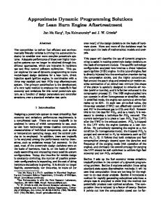
1.2 Self-Tuning A self-tuning system, illustrated in Figure 2, works on top of the dynamic verification mechanism. It monitors the error rate of by the core to determine the clock and voltage of the system. If the system is to function correctly the checker must be designed such that it is more robust and therefore able to detect when the core is operating outside of its range. For this to be the case the maximum operating frequency has to be determined relative to the checker. Additionally, changing frequencies requires a small amount of time, so it is necessary to establish an algorithm that balances the time lost to tuning and the performance gained from the frequency change. There are several key components in this design necessary to support variable frequencies inside of the chip. These components include: analog tuning support, a core, a checker, a register file with roll back capabilities, and a bus interface that compensates for variable frequencies. The analog components must be constructed to allow the internal chip to adapt to new
P re d ic tio n S tre a m : ins ts, in p u ts, a d d rs a n d re s ults
C h e c k e r P ro c e sso r C h e c k e r P ip e lin e
L0 cac he
L2 cac he
Figure 1: Dynamic Verification System Architecture.
CT
C hec ker R F
C ore P re diction s C ore
C h ecker
C lo ck C lock G en erato r
E rror R ate C lock C o ntro l
Tun in g
Figure 2: Self-Tuning Feedback diagram frequencies. We have constructed a delay lock loop (DLL) to slowly track frequency changes from an external voltage controlled oscillator. Furthermore, to make the hardware tune itself, a feedback path must be constructed with hardware support to make sure the transition occurs correctly. In our case a core is coupled with a checker that uses the error rate of the core to determine when the tuning should take place. Our hardware support consists of three additional special digital structures. The first is a register file that supports the role back of the checker state into the core state when an error has been detected. The second is bus interface that can tolerate the variable frequency of the chip. Finally, a special tuning block is added to our design to control the frequency adjustment and ensure its proper completion. The following section describes these blocks (DLL, Core, Checker, Register File, Bus Unit Interface, and Tuning block) in detail. The proceeding section describes the methodology used to implement the design. A description of the verification environment follows this. The paper concludes with some discussion of the future work and conclusions on the project.
2 Design Description The hierarchy of the design that we have constructed that implements self-tuning is shown in Figure 4. All of the top level modules are described in detail in this section.
2.1 DLL Design To synchronize the Remora chip with an external clock, a delay lock loop (DLL) and a phase lock loop (PLL) is needed.
Figure 3: Custom Layout of the DLL A PLL has the advantage of being programmable and is well suited to frequency multiplication. Also, PLLs do not pass any jitter from the reference clock to the output clock since PLLs generate their own clock. The clock signal generated by a PLL does, of course, have a certain amount of inherent jitter. The feedback loop used to adjust a PLL's frequency of oscillation has the possibility of becoming unstable since it is a second order system. This places a stringent stability requirement on the loop gain and complicates the design and implementation of the PLL. A DLL was selected for the clock phase generation because it is simpler to implement and meets our requirements. The custom layout is shown in Figure 3. A block diagram of a DLL is shown in Figure 5. The basic components of a DLL are the delay line, a phase detector or a phase frequency detector (we chose the later), a charge pump, and a loop filter. Both DLLs and PLLs can suffer from false locking problems, which occur when the DLL/PLL locks to two or more periods of the input clock. A DLL is only a first order system and therefore has no stability problems. The DLL has one more attractive feature that is of particular interest to this application. The DLL can follow incoming frequency changes in real-time without ever becoming unlocked. This feature will ultimately give the Remora chip its fast tuning times. The DLL will be operating in close proximity to a large synchronous digital system. This implies that the strongest noise source will be the power supply. Also noise from the TOP LEVEL REM ORA
Tuning
TO P L E V E L D ig ital
C o re
F u n c tio n a l U n its
RFs
B u s In ter fa ce
TO P LEV EL A n a lo g
C h e ck er
D LL
IF / G S H A R E
C ore R F
C o r e I ca c h e*
IF C H E C K
ID S TA G E
C hk R F
C o r e D ca c h e *
ID C H E C K
E X S TA G E
C h k I ca c h e*
EX CHECK
M E M S TA G E
C h k D c a ch e *
M EM CHECK C O NT RO L
F u n c tio n a l U n its
Figure 4: Design Hierarchy (*in progress see Bus Unit Interface)
E x ter n a l V C O
C lo c k P h a se F req u en cy D e te c to r
C h a rg e Pum p
Loop F i lt e r
VCDL
C lo c k
Figure 5: DLL Block Diagram The Instruction Decode stage [ID] is responsible for extracting all of the information that will guide the instruction’s execution down the rest of the pipeline. The ID stage also contains forwarding logic that determines the sources of values for the operands into the EX stage. The Execution (EX) stage contains all of the function units and is responsible for the actual mathematical computation (if any) in the instruction. Eight functional units are used in this design, a multiplier, subtractor, adder, shifter, logic op, cmove, byte manipulator and comparator. The value of the active functional unit is placed on the shared tristate result bus. This structure was chosen to facilitate the replacement of a synthesized functional unit with a custom block. Redundancy between the functional units was removed via flattened synthesis.The multiplier is given 10 cycles to complete in the EX stage. The Memory (MEM) stage performs any memory operation that is required. A hit signal is generated to indicate when the transaction is complete. The MEM stage interfaces to the bus unit interface (BUI), discussed later. Since only one memory stage is used, no store forwarding is needed. In the Commit (CT) cycle, the instruction destination register is written with the result computed in the EX stage or loaded from memory (during the MEM stage).
transistors themselves can become a significant source. The design must be tolerant of these sources of noise and still meet the specifications. The first cell in the DLL is the phase detector or phase frequency detector. The type chosen is the set reset delay latch. This type of detector will not lock harmonics of the input frequency. It also has the advantage of tracking both phase differences and frequency differences. The only downfall of this detector is that there is a dead-zone when the DLL is locked. This dead-zone can cause unnecessary jitter. By changing to the dual flip-flop detector the dead zone can eleminated.The charge pump was designed to be as simple as possible, while controlling feed-through currents. This design gave consideration to these feed through currents. The delay line utilizes twenty current starved elements to provide the delay. Eighteen of the delay elements are used to create the delay with the other two ensuring that all stages see the same loading.
2.2 Core The core design is a fairly straightforward five stage pipeline, with forwarding logic and support for multicycle instructions. The core and the checker implement the majority of the Alpha integer ISA. The general structure of the pipeline and the critical paths that determine its operating frequency will be described. A further analysis of possible improvements is provided in the future work section.
2.2.2 Core Critical Path Analysis The critical path analysis was done using the report_timing command in Synopsys, after all constraints on the design had been satisfied. We discuss later how the constraints for the design, including output load estimates, were developed.While Synopsys can only estimate the delay due to capacitive interconnect, this is a reasonable starting point for the timing analysis. The critical path for branch resolution, shown in Table 1, is a well known bottleneck for CPU performance. Many companies are combating this path by pushing branch resolution
2.2.1 Pipeline Structure The pipeline is a five stage pipeline as illustrated in Figure 6. The frontend fetch stage [IF] contains a GSHARE branch predictor [7] that speeds up execution by reducing the number of mispredicted branches. The GSHARE is trained with the branch target calculations from the execute stage, where branch mispredictions are also resolved. IF
ID
EX
M EM
CT
0 OP B FU ACTIV E 0 OP A
g sh ar e
FU A CTIV E
0 OP B
To R F
FU ACT IVE 0 OP A FU A CTIV E
To / F ro m I n s tr u c t io n M em o ry
F rom R F
Figure 6: Block Diagram of the Core Pipeline
To / F r o m D a ta M em o ry
deeper into the pipeline, which is evident by increasing branch misprediction latencies [8]. Path Component
Time (ns)
Flip Flop Propagation Delay
.17
Next PC calculation
1.31
Branch Misprediction Analysis
.7
Gshare update
.81
Flip Flop Setup Time
.27
Total
3.26ns
2.3.1 Checker Control Logic As mentioned above, the only state in the checker modules is a register to hold the instruction; the rest of the state lies in the Checker Control Unit shown in Figure 7. This unit is a simple three-state finite machine. This strongly connected state machine uses the results of the checker modules to determine whether an instruction executed correctly. A done signal, derived from a cycles counter and the memory stall lines, is used to indicate when checking status should be evaluated. A NEW_INST flag is sent from the core to the checker to indicate that an instruction is ready to be checked. Finally, a watchdog timer is used to detect when the core is no longer making forward progress. When it expires, it generates a timer_expired
Table 1: Timing path of the 64 bit CPU in the Artisan .18 technology (typical operation)
RESET !N E W _ IN S T & & !tim er_ exp ired
2.3 Checker ID L E
The checker, shown in Figure 8, acts very much like another pipestage during check mode. Each checker module takes in the values from the core and compares the values against its computation to determine whether the instruction is valid. Table 2 summarizes how these values are checked. The routing muxes present in the checker are reconfigured, when an error is detected to execute the instruction and then reload the core with the checker’s state. Since the checker modules do not contain flip-flops (with the exception of a register for the instruction from memory), only one instruction is allowed to execute in the checker pipeline during an error recovery. This gives it high latency, but makes it simple to design. The assumption is that there will be fewer errors, so their latency will not significantly effect performance.
tim er_ ex pired N E W _I N S T d on e & & !N E W _ IN S T & & CORRECT
d on e & & !N E W _ IN S T
d o ne& & !C O R R E C T
CHECK
EXECUTE d o ne& & N E W _ IN S T !d o ne
!do n e|| (do n e& & C O R R E C T & & N E W _ IN S T )
Figure 7: Checker Control Unit State Diagram In s tru ction M em o ry
In p u ts F ro m C o re R eg i s te r A # a n d v a lu e R eg i s te r B # a n d v a lu e D e st in a t io n # a n d v a lu e A lu R es u l t I n s tr u c ti o n PC N PC
C o re Va lu e s
< A d d re s s , D a ta , S ta ll>
IF C H E C K
ID C H E C K
IF C H E C K
< P C , In s tru c tio n >
< IF C O R R E C T, S TA L L >
EX C H E C K
R eg ister F ile
< P C , In s tru c t io n >
1 < P C , In s tru c tio n , R e g s >
M EM CH ECK
ID C H E C K
CO NTRO L < ID C O R R E C T >
0
b)
< R e g is te rs , In s tru c tio n >
1 < R e g is te rs , A lu R e s u lt , In s tru c tio n >
EX CH ECK
0
A rch itected S tate
< A lu R e s u lt, R e g is te r s , In s tru c tio n >
1 < R e g is te rs , A lu R e s u lt , In s tru c tio n , N P C >
CT
< R A # , R A Va l R B # , R B Va l>
IF C H E C K
ID C H E C K
CT
M EM C H EC K < M E M C O R R E C T, S TA L L >
0
EX C H E C K
M em o ry < A d d re s s , D a ta , S ta ll>
“ ro u tin g ” m ux c o n tro l
M EM CH ECK
CONTROL
a)
in s tru c tio n v a lid a n d s ta ll s ig n a ls
CT
CO NTRO L
c)
Figure 8: Checker Processor Pipeline Structure for a) a single wide checker processor, b) a checker processor in Check mode, and c) a checker processor in Execute mode
Stage
Any Instruction
IF Check
CheckerInstruction = IMEM[CheckerPC] IFCorrect= ((CorePC==CheckerPC)&&( CoreInstruction == IMEM[CheckerPC])) IFStall = ! ICACHEHIT
ID Check
CheckerOperand A= RegisterA CheckerOperand B =(Immediate_Alu_Op) ? Immedaite : RegisterB CheckerRDEST # = RC field IDCorrect= (Core_RDEST#==CheckerRDEST#)&& (Core Operand B == Checker Operand B)&& (Core Operand A == Checker Operand A)
CheckerOperand A=RegisterB CheckerOperand B= Immediate CheckerRDEST # = RA field
EX Check
CheckerResult = (Operand A [aluop] Operand B) EXCorrect = (Core AluResult == Checker Result)
CheckerResult= (OperandA + OperandB) EXCorrect = (Core AluResult == Checker Result)
Checker Result= (OperandA + OperandB +4)>>2 EXCorrect = (Core AluResult == Checker Result)
MEM Check
CheckerNPC = PC + 1 MEMCorrect= (CoreNPC==CheckerNPC) MEMStall = 0
CheckerNPC = PC + 1 Checker RDESTValue = DMEM[Aluresult] MEMCorrect= (CoreNPC==CheckerNPC)&& (CoreRDESTValue==CheckerRDESTvalue) MEMStall= ! DCACHEHIT
Checker NPC= (ConditionTrue)AluResult : PC+1 MEMCorrect= (CoreNPC==CheckerNPC) MEMStall = 0
CT
PC=NPC RDEST#=RDESTValue WBStall=0
PC=NPC For Load: RDEST# = RDESTValue WBStall=0 For Store: DMEM[AluResult]=RDESTValue WbStall= !DCACHEHIT
PC=NPC WBStall =0
ALU
Load or Store
Branch CheckerOperand A=Checker_PC CheckerOperand B= Immediate CheckerRDEST # = RA field IDCorrect= (Core_RDEST#==CheckerRDEST#)&& (Core Operand B == Checker Operand B)&& (Core Operand A == Checker Operand A)
IDCorrect= (Core_RDEST#==CheckerRDEST#)&& (Core Operand B == Checker Operand B)&& (Core Operand A == Checker Operand A)
Table 2: Description of checker module functions signal, and the checker will execute the next instruction in the program and reset the core. Path Component
2.4 Register File Checker Wr Port
Time (ns)
Propagation Delay- Flip Flop
.17
Routing Mux Signal Logic
.20
Instruction through mux to ID_CHECK
.43
ID_CHECK Execution (ID_CORRECT)
1.39
Control Logic Commit Signal
.30
Instruction Latch Logic
.66
Setup Time- Flip Flop
.11
Core Wr Port
RF
RF Core Rd Ports
RF
RF
Checker Rd Ports RF Controller
Total
3.26ns
Table 3: Timing path of the 64 bit CHECKER in the Artisan .18 technology (typical operation)
2.3.2 Checker Critical Path The critical path of the checker, shown in Table 3, resulted from synthesizing to meet the time of the core. At the start of the cycle the new state is loaded into the Checker Control, which sets the state of the routing muxes. The instruction is then fed to the ID_CHECK, which verifies that all of the correct fields have been decoded. It returns the correctness of the decode to the Control Logic, which determines whether the instruction should commit. If the instruction is to commit, a new instruction is sent to the checker latches for checking. Since, the critical path goes through the ID_CHECK and not the EX_CHECK where the functional units are, it is easy to see that this design can be synthesized to operate at higher speeds. Additionally, the routing mux control signal logic can be overlapped with the commit logic and stored in a flip-flop for the following cycle. Changing the synthesis script and latching the mux control signal in the previous cycle should yield an operating frequency below 3ns.
Figure 9: Register File Block Diagram
The register file, shown in Figure 9, was constructed using the Artisan register file compiler. However the version we have access to supports only register files with one write and one read port. The Alpha ISA requires two read and one write port. So two 1-wr, 1-rd port register files were put in parallel with a common write bus to form a 1-wr 2-rd port register file. This was done for both the core and the checker. Logic was then added that allowed the core register file to be written with the checker register file’s values (sequentially) if the checker detected and error.
2.5 Bus Unit Interface The Bus Unit Interface (BUI) is the connection of the internal memory buses to the memory offchip. Presently, this is implemented as a bus switch. The BUI takes in the buses from the core and checker and stalls them until the data is available. The two external data buses (with matching address buses), are assigned to the requesters in a round-robin fashion. Bus stealing is possible when the person assigned the bus does not require it. The bus is held for X number of cycles, where X is a
value placed on the bus wait cycle pins of the chip. This design allows for a variable frequency core, because it assumes an asynchronous external memory is used. The wait states are programmed to match the memory that is used. The REMORA chip is very similar to a chip multiprocessor in memory requirements. There are two separate instruction requests per cycle (assuming perfect throughput) and possible two more data requests. Because of this, bringing some of the memory onchip will yield large performance benefits. We have already started work on incorporating a memory hierarchy. The difficulty here is that to prevent false detections of errors in the checker, the memory used by the checker and core needs to be kept consistent. Additionally, the core can not be allowed to do anything that can’t be corrected by the checker. So if the core were to write a value into incorrect memory location, the checker would not be able to (easily or efficiently) detect this error. To prevent this our current development does not allow the core Dcache to write back and uses a special queue to pass the memory values to the checker. The checker then does all of the ‘precise’ memory operations.
2.6 Tuning The tuning block facilitates the frequency tuning of the system through the use of a global feedback system as previously shown in Figure 2. When tuning the tuning control, checker, and DLL all play a role. The checker is reasonable for making the decision of when to frequency tune. When that decision is made the checker will provide an 8 bit unsigned number. This number is sent to a on-chip 8 bit digital to analog converter (DAC) (completed in previous course work). The DAC will then perform the conversion and send a DC representation of the digital value to an off-chip voltage controlled oscillator (VCO) time base. In turn, the VCO will generate a clock signal that is proportional to the checker request. This clock is fed into the DLL which will attempt to stay in lock with the new clock signal, hence, frequency tuning the system. One might ask what if the DLL become unlocked? This problem was indeed a difficult issue to solve. However a rather simple and well though out solution was implemented. Consider the tuning system described in the previous paragraph, if the DLL should become unlocked and left to provide the time base for the core, the system would violate timing constraints. To correct this issue the DLL was design to provide a continuous digital signal called is_locked. This signal is feed to the tuning block which is continuously monitoring the signal. When the DLL becomes unlocked a new minimum speed clock, from an on-chip oscillator, is muxed into the core and checker through a synchronizer. This clock switching will allow the system to continue functioning during an unlock. Meanwhile the tuning block has shutdown the external clock input to the DLL and begins reset sequence for the DLL. Upon the completion of the reset the DLL is allow to relock the external clock. Once this external clock is locked, it is muxed back into the system through a synchronizer. The overall function of the tuning block is to frequency tune the system. During the tuning sequence the system never halts execution of instructions. In fact the system never halts execution of instruction even if the new frequency in unlockable in real-time. Overall the tuning block allows for real-time tuning in a non problematic case and retuning in less then 100ns is cases of unlocking while continuously executing instruction.
C o n ce p t P h as e D es ig n P h a se S y n th e sis P h a se P la ce a n d R o u te P h ase
L o g ic M a p p in g P ro b lem s T im in g P ro b le m F ix L a y o u t E r ro rs
L ay o u t Ve rifica tio n P h ase M an u fa ctu rin g P h as e
F a b ric atio n P ro b lem Found D e sig n B ug Found
P o st-M an u fac turin g P h a se Figure 10: Standard Asic Flow
3 Design Methodology A standard ASIC flow as shown in Figure 10 was used in this design. In the Concept Phase, a specification of the hardware is written so the correct functionality was clearly defined. The next step is the Design Phase, during which the specification is captured in some type of hardware description. The synthesis phase concentrates on the mapping of this hardware description to logic gates. The logic gates are then transformed into a physical layout, using place and route. Timing is also examined during this step to see if the design still meets the specification. The layout verification step ensures that the layout captures the correct functionality (through layout versus schematic, LVS) and that it will be manufactured correct (through design rule check, DRC). The Manufacturing Phase takes fabricates the circuits. Finally, the fabricated wafer is tested during the post manufacturing phase. This section will detail the efforts and the accomplishments that we have made in the first five stages.
3.1 Concept Phase The concept phase is essential to the testing process, as it determines what the correct behavior of the design is. We implemented a subset of the Alpha 21264 instruction set which included large majority of the integer instructions. Presently, our implementation ignores the vector math instructions and non-quadword load stores. The load/stores are supported in the on-chip memory hierarchy that is in development.
3.1.1 Golden Brick Once the behavior of the system was established, a model that fits the specification was constructed. The verification model, or “Golden Brick” as it is sometimes referred to, is used to generate the expected results. Legacy designs and simulators are two common examples of “Golden Bricks”. An Alpha 21264 workstation was available for comparison, but because of the difficulty of viewing all the registers and mem-
ory space in a real chip, the SimpleScalar Alpha simulator [6] was also used to model the hardware and program execution. This simulator makes it easy to track changes to both the registers and the memory space, which can be used as references for the Verilog model to check against.
3.1.2 Design For Test Provisions for testing the design were also developed during the concept stage. It is desirable to use built-in-selftest (BIST) on the checker to aid in the manufacturing tests. We have shown that, since the control of the checker is minimal, it is straightforward to get a high stuck-at-fault coverage. The details of the BIST vector creation can be found in [5]. Scan chains are also used in the prototype chip. Since these chains do add latency, it is assumed that if this chip ever reached production levels the scan chains would be removed. Finally, a cache bypass is present in the current development of the memory hierarchy. The cache bypass forces the chip to go straight to a memory bus for all of its data. This makes it easy to control the values sent and allow for the testing of the core logic in the presence of a problem in the memory hierarchy. Finally we plan to memory map a USART on the chip so that we can control the chip via RS-232. The USART will be supplied via an IP block.
3.2 Design Phase In an ASIC flow, such as the one used the design phase usually consists of writing a hardware description in Verilog or VHDL. Our current revision of the code contains over 17,000 lines of synthesizable Verilog, which is structured as previously shown in Figure 4. The Remora chip was designed using an incremental approach. The first version started with a three stage pipeline, which is fairly straightforward since, there are few data hazards to worry about (we needed only a single stage bypass network). The focus of this design was decoding of the instructions. Next we added additional stages to the pipeline to better distribute the delay, and achieve a higher clock speed. A branch predictor and support for multi-cycle functional units were also added to increase performance. The third revision of the design added a memory hierarchy. The key benefit of the incremental approach is that each revision adds only a few features so that debug work is limited to a smaller code space.
3.3 Synthesis Synthesis takes a logic representation and maps it to a specific library gate implementation. To synthesize the Remora chip, a snapshot of the Verilog code was first analyzed in design_compiler (A GUI Synthesis tool from Synopsis). The top design was implemented, and the “characterize” function was used to develop constraints for the lower modules. This facilitated the synthesize of lower modules with good estimates of the loads and delays that are connected to them. This ensures that the output gates are properly sized. We also needed to make sure that multi-cycle paths through the multipliers and the checker in recovery mode were accurately modeled. Scripts were created for each module so that it could be synthesized separately. In total over 55,000 lines of synthesis scripts were generated. The upper module scripts read in the database files of the lower modules and direct the tool not to touch the design. The module was then synthesized; after synthesis the don’t touches’ were removed and an incremental compile with boundary optimization was performed. This
method allowed as to get the performance of a flat design with the time-saving advantages of a hierarchical method.
3.4 Place and Route Place and Route was performed using the Silicon Ensemble tool from Cadence. Originally, the whole design was placed and routed as one large block. While this produced a fairly dense design, we were unable to verify such a large block with the tools described in the next section (We allowed a run to go 2 days before giving up). To overcome this, we placed and routed the checker, core and register file separately. These designs were saved as lef files and then read in for place and route of the Remora chip. We also added 16K of RAM, which is to be used with our memory hierarchy when it is completed. All of these large macro blocks were manually floorplanned. The flat design, shown in Figure 11a, resulted in a chip that is roughly 1.8 mm on a side. The hierarchical approach, shown in Figure 11b, with the 16K of cache was 4 mm on a side.
3.5 Layout Verification The layout verification includes two steps. The first is to see if the layout follows the rules set by the foundry of how the circuit must be designed. This was done via DRC (design rule check) using the DIVA tool in the cadence design environment. First, the gdsii from silicon ensemble was streamed into cadence where it was merged with the gdsii of the standard cells, RAM and RF macros. Next, a compatible deck from the MOSIS website was downloaded, because Artisan uses 45 degree bends in some of its gates. With this new deck we were able to get the blocks to DRC with almost no rule violations. In the core, errors were encountered in a RAM due to poor placement of a filler by silicon ensemble. When the fill area was better defined, this problem disappear. The resulting design had fewer then 20 metal spacing or metal notch errors that were easily fixed. The deck required .23 µm between the metal lines and the actual spacing was .225 µm. The second layout verification that must be conducted is layout versus schematic (LVS). Here the transistor layout is extracted from the gdsii and compared to the spice netlist. The LVS was performed on the flat design (11a), however the hierarchical design (11b) has not been put through LVS yet. This layout contains the start of the memory hierarchy that we are adding to the completed design to enhance its performance before fabrication.
3.6 Top Level Organization The synthesis and APR (automated place and route) portions of the design flow were organized with a makefile. Makefiles inherently track changes to the files and execute commands only when one of the dependences is modified. This means that if in a hierarchical place and route when something in the Verilog of the checker is changed, it would resynthesize the necessary modules in the checker and then recreate the macro block. This results in considerable time savings.
4 Design Verification The primary method for verification was running actual code on the verilog, by accessing a simulated memory structure. Half of the programs were written in actual assemble and the other half were written in alpha is a assembly mnemonics and then assembled with the GAS compiler[9]. We have also developed a random code generator. The generator uses branch areas at the top and bottom of a main program code segment.
Register File
Register File
16K RAM
Tag Cache
4mm
1.8mm
Core Branch Predictor a) b) Figure 11 a) The Layout of the Remora as a flat Place and Route. The layout is shown with only metal 1 and 2 visable and consumes roughly 1.8mm on a side. b) The hierarchical place and route of the system. 16K of cache was added to this layout for the memory hierarchy that is under construction. This layout is shown with only metal 1 visable and consumes roughly 4 mm on a side. DRC clean (with the exception of a few metal spacing probThe code generator randomly selects an instruction. If the lems that are fixed by hand). instruction is a non-control instruction it is simply placed in the main program segment. If the instruction is a branch or jump, the registers are set with value to make the branch land 7 Acknowledgements in an open slot in the upper or lower branch region. This area is then loaded with a corresponding branch back to the main code We would like to acknowledge Matt Guthaus for his assissegment. This allows us to test branches without creating an tance as the teaching assistant for EECS627. We like to thank infinite loop. Chris Burke for his assistance with the initial implementation of the gshare and memory hierarchies. Branch Predictor
5 Future Work There are four areas that we would like to improve on the design. The first which has been eluded to before is the addition of an on-chip memory hierarchy. The second is that we would like to research optimizing tuning algorithms for determining when to switch frequencies and by what percentage, through the use of external hardware. This is a potentially lucrative research field for computer architecture. The third thing is to increase the testability through the addition of a USART IP block. Finally, we want to examine the performance benefits of adding custom modules. As mentioned above, the EX stage was designed to make this fairly straightfoward.
6 Conclusions We have completed the design of a first prototype of Remora, which is a self-tuning dynamically verified processor. The design has been synthesized to an operating speed of 300Mhz. The place and route of the design has been done using both flat and hierarchical approaches. Using the hierarchically placed and routed design the macro blocks have been
Checker
8 References [1]T. Austin. “DIVA: A Reliable Substrate for Deep Submicron Microarchitecture Design”. In Micro-32, Nov 99. [2]T. Austin. “DIVA: A Dynamic Approach to Microprocessor Verification.” The Journal of Instruction-Level Parallelism Volume 2, 2000. [3]S. Chaterjee, C. Weaver and T. Austin. “Efficient Checker Processor Design.” In Micro-33, Dec 2000. [4]M. Mneimneh, F. Aloul, C. Weaver, S. Chatterjee, K. Sakallah, and T. Austin, “Scalable Hybrid Verification of Complex Microprocessors,” in the Proc. of the Design Automation Conference (DAC), 2001. [5] C. Weaver and T. Austin. “A Fault Tolerant Approach to Micropro cessor Design” In DSN-2001, July 2001. [6]D. C. Burger and T. M. Austin. The simplescalar tool set, version 2.0. Technical Report CS-TR-97-1342, University of Wisconsin, Madison, June 1997. [7]S. McFarling et all. “Combing branch predictors.” Technical Report TN-36m Digital Western Research Lab, June 1993. [8]Vikas Agarwal and M.S. Hrishikesh and Stephen W. Keckler and Doug Burger “Clock rate versus (IPC): the end of the road for conventional microarchitectures.” ISCA 2000, 248-259. [9]http://www.gnu.org/software/binutils/binutils.htnl