Requirements Engineering in the Development of Large-Scale Systems Sascha Konrad and Michael Gall Siemens Corporate Research, Inc. 755 College Road East, Princeton, NJ 08536, USA {sascha.konrad,
[email protected]}
Abstract Requirements engineering is arguably the most important activity in the development of complex, software-intensive systems. Generally, the higher the complexity of the system under development, the more exacerbated the importance of good requirements engineering becomes. While numerous researchers in academia have focused on requirements engineering, there is still a need for practical guidelines that scale to real-world applications. This paper presents requirements engineering challenges faced and lessons learned addressing these challenges in a large-scale industrial project. The implementation of these lessons greatly contributed to the success of the project.
1. Introduction Requirements engineering is arguably the most important activity in the development of complex, software-intensive systems [8] [11]. In our experience, no other activity has greater impact on the success of a system development project. Generally, the higher the complexity of the system under development, the more exacerbated the importance of good requirements engineering becomes. In this paper, we present several lessons learned while addressing requirements-related challenges in a large-scale industrial project. High-quality requirements are important, since they serve as a baseline among multiple teams on the product that needs to be developed, and provide a basis for planning, validating, and testing. A system that does not adhere to its requirements (or to requirements not aligned with customer expectations) will not fit the purpose it was intended for and likely fail [5]. In addition, the cost of correcting errors introduced early in the requirements phase is known to be significantly more expensive than the cost of correcting errors introduced in later stages [3], leading to budget and/or time overruns, possibly even to project cancellations. While numerous researchers in academia have focused on requirements engineering, there is still a need for practical guidelines that scale to real-world applica-
tions. In industry, however, lessons learned are often not documented, which results in projects repeating the same avoidable mistakes. In order to address this problem, we collected lessons learned based on eight challenges faced in a large-scale industrial project. We believe that these lessons are valuable and will increase the probability of success in a project facing similar challenges. The presented challenges and lessons learned have been reviewed by multiple requirements engineering experts at Siemens Corporate Research, with the general agreement that similar challenges exist across projects with similar characteristics at many companies and that the techniques presented in this paper are generally applicable to these projects. In our experience, the measures taken to address the challenges in the project greatly contributed to its success. The remainder of the paper is organized as follows. Section 2 presents an overview of the project the lessons were derived from. Section 3 describes the challenges faced in this project. Section 4 presents our lessons learned on how to address these challenges. Finally, Section 5 gives concluding remarks and discusses directions for future work.
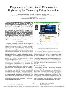
2. Project Description The project from which we derived the lessons presented in this paper was a large-scale system development project with more than 4,000 customer requirements. For the system under development, several hundred distributed components had to collaborate to achieve the required functionality. An existing infrastructure and legacy systems had to be integrated. Figure 1 shows the elided V-model (adapted to systems engineering) used in this project. As part of the system engineering process, the customer requirements were refined into system requirements, where issues such as incompleteness, ambiguity, inconsistencies, or contradictions were resolved. A system architect then created a high-level system architecture and end-toend workflows, and assigned the system requirements to the identified subsystems.
• Changing technology (C4): Since the project spanned several years, technological changes during the time had to be taken into account and accommodated. • Distributed teams (C5): Project teams were distributed geographically across continents. Previous studies have shown that this distribution often leads to issues, such as coordination and communication challenges [15]. • Traceability (C6): Full bi-directional traceability was required for all development artifacts, including requirements. Creating and maintaining the traces was a difficult task, due to the amount of time and manual effort required. • Scope change and creep (C7): Scope change and creep is natural and unavoidable in large projects. For instance, due to changes in technologies and processes, the customer requested modifications to some of their requirements. Accommodating the change in scope while still meeting the project milestones was demanding. • Resource fluctuation (C8): In long-term projects, it is inevitable that team members phase in and out of the project. Providing easy access to project knowledge for all team members, such as upcoming deadlines, past deliveries, decisions/trade-offs taken, and project risks, was a challenge.
4. Lessons Learned Figure 1: Artifacts and corresponding tests (elided) For system requirements assigned to software subsystems, more detailed software requirements were created and documented in a software requirements specification (SRS). Subsequently, a software architecture was created to satisfy the requirements captured in the SRS. For each of these artifacts, corresponding tests were created.
This section describes lessons learned during the setup and execution of the previously outlined project, and ties the lessons learned back to the challenges presented in the previous section. The lessons learned are classified according to the CMMI process areas requirements development and requirements management [6]. Table 1 provides an overview of the lessons learned and the challenges they address. In the remainder of this section, each of these lessons is explained in more detail.
3. Challenges Faced This section lists some of the challenges that were faced in the project: • Large number of customer requirements (C1): The larger number of customer requirements posed challenges for analyzing, specifying, and managing requirements. • Limited, formal interface to customer (C2): Communication with the customer was formal, meaning that official submittal and review processes had to be followed on most issues. This level of formality greatly increased the time required to receive feedback and clarifications from the customer. • Management of customer expectations (C3): Since a large and complex system was being developed, but early prototypes of the system were being shown to the customer, expectations of the customer on how far development had already progressed needed to be properly managed.
Table 1: Challenges and lessons learned Challenges C1, C5 C1, C2, C3, C7 C1, C5 C4
C6, C7 C6 C5, C6 C5, C8 C5, C7
Lessons learned Requirements development Develop a well-structured feature list. Obtain a good understanding of customer requirements. Use specification approaches that scale. Separate requirements and design decisions. Requirements management Establish a traceability model. Define a traceability measurement process. Provide project status visualization. Establish effective documentation standards and review processes. Create effective hierarchical CCB structure.
4.1 Requirements Development Requirements development denotes activities related to specifying and analyzing customer and system requirements [6]. Subsequently, we discuss lessons learned pertaining to requirements development. Develop a well-structured feature list (C1, C5): A feature is a required, externally accessible service of the system. It is common practice to organize software requirements specifications according to features [17]. In order to create a well-organized SRS document, time and effort needs to be invested into creating a well-structured list of features; otherwise, several difficulties can be faced later in the project. Since project schedules are often created according to features, not understanding the complexity of features and their interdependencies may lead to cost and time overruns. This problem is exacerbated for large projects with several distributed teams. In addition, once the SRS document has been created, changing the feature structure is expensive, since such changes may require approval by the customer, reorganization of document, updates to traces, etc. The cost of these changes is increased if the features are organized in terms of a graph structure. In our experience, it is necessary for the requirements engineers to invest significant time and effort early in the project into developing a well-thought-out list of features. We found it useful to create feature descriptions on several levels and arrange them in terms of a hierarchical feature model. The decomposition of coarse-grained into fine-grained features simplifies the assessment of completeness and provides a means for hierarchically structuring the SRS document. Obtain a good understanding of customer requirements (C1, C2, C3, C7): The large number of customer requirements made understanding the various aspects of the system under development challenging. This problem was exacerbated by the fact that even the customer often did not have a proper understanding of the requirements. The reason for the lack of understanding was that the knowledge was fragmented within the customer organization. In addition, the system under development was intended to, partially or completely, replace workflows that were at that time executed manually. In order to address these challenges, we found it important to clarify customer requirements early in the development process. The development of operational concepts based on a high-level architecture for the major features of the system is important to clarify workflows with the customer. Another important tech-
nique we used was involving the customer in the requirements engineering process through prototyping sessions, which are an effective means for facilitating communication with the customer and driving the requirements refinement [18]. The sessions allowed domain experts of the customer to view whether our interpretation of the requirements was aligned with their workflows. If not, the prototyping sessions provided rapid feedback for correcting the system requirements, before committing to design and coding. The use of prototypes, however, also raised issues. One issue was that customer expectations needed to be sufficiently managed. Once a functional prototype was demonstrated, it was important to remind the customer that the prototype was not the basis for the final system that will be delivered and was therefore no indication of development progress. Use specification approaches that scale (C1, C5): It is common practice to capture functional customer requirements in terms of use cases. Use cases provide an external view on the behavior of a system [10]; the system is treated as a black box. Requirements on the system level, on the other hand, are commonly captured in a different form, such as in the form of “shall” statements. For a complex system with numerous requirements, the number of such statements can be extensive. We found the understandability and manageability of a large number of requirements as “shall” statements difficult, even when supported by tools. In order to specify the software requirements, we employed an approach similar to the one advocated in [1] for system requirements. For the system under development, a high-level architectural description already existed and was used for classifying the system requirements. In order to reuse this architectural knowledge in the SRS, we created grey-box use cases, which are white box on the system level (since they take the interactions between software subsystems into account), but black box on the subsystems level (since they treat software subsystems as black boxes). As such, the use cases not only capture the external view of the system behavior, but also describe the interaction between software subsystems. In our experience, this approach greatly increased the readability and maintainability of the software requirements specification. Stakeholders, including the customer, agreed that the use case representation was easier to understand and review than the “shall” statements in an earlier version of the SRS. The test team reported that the creation of software validation test cases was facilitated, since the grey-box use cases capture the sequence of interactions between software
subsystems and do not only capture “happy path” scenarios, but also variant paths. Separate requirements and design decisions (C4): It is commonly accepted that requirements engineering in large-scale systems shares numerous characteristics with so-called wicked problems [14]. For example: The formulation of requirements is difficult, there is no hard rule when to stop doing requirements engineering, and the design solutions created to address the requirements are not right or wrong, but merely better or worse. Furthermore, the attempt of designing a solution often gives new insight into the problem and, therefore, affects the problem description. For our project, this nature of requirements engineering had two implications. First, software requirements were changing constantly as designers were creating solutions to satisfy the requirements. In order to mitigate this problem, the process we used attempted to minimize change, but also reduce the cost of unavoidable change. Change can be minimized by attempting to understand the requirements of the software and the characteristics of a solution thoroughly before committing to design. Prototyping sessions with the customer helped in this respect. Cost of change can be minimized by having a clear separation of concerns and modularization of the requirements specification, and through avoiding unnecessary redundancy. The second implication we found was that customers and architects tended to describe problems in terms of solutions. This solution bias may have potentially led to the requirements specifications containing design details. Especially in long running projects, technology changes affect the system design. Even if the customer requirements are subsequently not affected, a system requirements specification with design details will still need to be updated to accommodate design changes. As such, problem and solution description should be kept separate. While a perfect separation is not feasible (system requirements and architecture are “inevitably intertwined” [20]), having as much separation as possible facilitates technology change.
4.2 Requirements Management Requirements management is concerned with managing the requirements and assuring that project plan and developed artifacts adhere to the requirements [6]. Subsequently, we discuss lessons learned pertaining to requirements management. Establish a traceability model (C6, C7): Establishing and documenting a well thought-out traceability model early in the project enables project
members to understand the tracing strategy and their roles and responsibilities. In addition to meeting customer or regulatory requirements, a well-defined traceability model supports impact analysis, facilitates product maintenance, aids project tracking, supports testing, and reduces the tracing cost and effort. The following issues arise when a traceability model is not established early in the project: 1) Ad-hoc tracing can lead to an insufficient amount of traces to support adequate impact analysis. 2) Ad-hoc tracing can lead to too much tracing, which increases the complexity and tracing effort. 3) An inconsistent trace model will result in limited benefits to the stakeholders. 4) When a well thought-out traceability model is defined, significant rework is needed to bring the ad-hoc tracing in-line with the defined model. In our experience, it is important to create a well thought-out traceability model up front that defines the artifacts to be traced, the granularity of tracing, how tracing is done, and those responsible for creating and maintaining the traces. Tracing with a purpose or an objective [7] makes it easier to define the artifacts and the granularity at which they are traced, and obtain buy-in from management and project members. If the process and tools used for tracing are not well defined and properly communicated, project members will be reluctant to support the tracing effort. Therefore, the traceability model and process description needs to be documented and accessible to all stakeholders. Define a traceability measurement process (C6): Defining a traceability measurement process enables project members to track the tracing progress and obtain information for tracking overall project progress. When defining a traceability measurement process, it is important to establish meaningful measurement objectives and corresponding measures to reduce needless measurements, prevent information overload, and ensure meaningful data points are not obscured. By automating the collection of measurement data, the collection process will collect more complete and accurate data [6] and reduce the data collection effort. With automation, the collection process can occur more frequently (or even on-demand) resulting in timely feedback to managers and developers. In our experience, collecting measurement data on a weekly basis, and providing an analysis of the data and assigning action items on a bi-weekly basis proved the best for our situation. By providing the unanalyzed measurement data on non-analysis weeks, project members were able to obtain feedback on fixes they applied to assigned action items during previous analy-
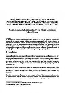
sis periods. The frequency of measurement and analysis activities was determined by conducting a small pilot process and making necessary adjustments as the project progressed. Provide project status visualizations (C5, C6): Providing simple easy to read visualizations that provide meaningful information of the project status will enable project members to quickly identify issues and take corrective action early. In addition, visualizations provide a high-level summary to management for monitoring the progress of project artifacts and subsystems. Project status can be visualized with the concept of a dashboard [4] [16] or a similar project-specific solution that collects measurement data from various sources and depicts the data graphically. Ideally, project status visualizations are posted in a communal area for all project members to see. For distributed teams, we found it necessary to store the visualizations under version control and transmit them to all project members via email. An alternative approach is to provide a project website with the project status visualizations and notify all project members of update via email. Once project members are introduced to the project status visualizations and the reporting process, they become eager to receive the report and see how their artifact stands up against the other project artifacts. For this reason, we advocate providing the unanalyzed measurement data (discussed above) to the project members so they can be proactive in addressing issues that may surface during the next analysis and visualization cycle. An example of a project specific tracing visualization is shown in Figure 2. For each type of requirement shown in Figure 1, the number of requirements traced and untraced is visualized. The number of verified traces and suspect traces (i.e., traces that need to be verified for correctness) between requirement types is also visualized. Establish effective documentation standards and review processes (C5, C8): The establishment of documentation standards is advocated by the CMMI [6]. Templates facilitate the creation of uniform requirements specifications. Once project templates are established, they can be reused by other projects in the organization. In order to facilitate the initial creation of these standards, industrial standard specifications, such as the IEEE 830 document [17] can be used. We have found that it is important to establish standards which should be followed throughout the requirements engineering process. Documentation standards are important to maintain consistency
among the work products of several requirements engineers, especially when they are distributed geographically, cultural differences exist, and staff turns over. Finally, guidelines and inspection checklists guide and assist stakeholders in assessing and reviewing the documents.
Figure 2: Tracing visualization It is well known that an effective review process is not only necessary, but it can also provide a significant reduction in cost by detecting defects early in the product life cycle [12] [2]. We have found that in addition to conducting the review, it is necessary to empower an individual, e.g., quality assurance manager or documentation manager, with the authority to ensure the review process is followed according to the documented timeline. Without the oversight, the review process can deviate from the planned schedule, since reviewers have a tendency to view reviews as “low priority” tasks. It’s important for this individual to work with the project planners to ensure sufficient time is allocated in the project schedule to conduct the reviews in a manner that realizes the benefits of the review process. Create effective hierarchical CCB structure (C5, C7): Instituting a change control board (CCB) has been identified as a good practice for software and systems
development [13] [9]. Typically, large projects have a hierarchy of CCBs [19] as shown in Figure 3. A lack of coordination among the CCBs will result in decisions, which have system level impact, being made in a lower level CCB without input from the other CCBs impacted by this decision. To further exacerbate this silo-type decision making, frequently these changes are not properly documented and communicated to the rest of the project.
Figure 3: Hierarchical CCB Structure In our experience, we have found that it is necessary to establish clear guidelines outlining when a lower-level CCB must escalate a change request to the higher-level CCB, when and how CCB decisions are communicated up and down the CCB hierarchy, and designating the CCB members responsible for communicating the decisions. Proper decision making that considers how a change request will impact the project as a whole and effective communication of CCB results will increase the probability that the project meets time and budget constraints.
5. Conclusions In this paper, we presented lessons learned for requirement engineering on a large-scale industrial project. In our experience, these lessons significantly contributed to the success of the project. There are numerous potential directions for future work. Since providing full traceability for the large number of artifacts was a challenge, we are currently investigating the use of dynamic tracing [7] to facilitate this task. In addition, we are investigating whether the use of model-driven approaches to requirements engineering and testing can further increase the quality of artifacts; while at the same time reduce the required effort.
Acknowledgements The authors would like to thank researchers in the Software & Engineering department at Siemens Corporate Research for their valuable feedback on this work, in particular Brian Berenbach, Beatrice Hwong, Juergen Kazmeier, Arnold Rudorfer, and Bill Sherman.
6. References [1] I. Alexander and T. Zink. Introduction to systems engineering with use cases. Computing & Control Engineering Journal, 13(6):289–297, Dec 2002. [2] B. W. Boehm. Software Engineering Economics. Prentice Hall, Englewood Cliffs, NJ, 1981. [3] B. W. Boehm and P. N. Papaccio. Understanding and controlling software costs. IEEE Trans. Softw. Eng., 14(10):1462–1477, 1988. [4] N. Cassaigne. The dashboard: a knowledge conversion tool. Engineering Management Conference, 2002. IEMC '02. 2002 IEEE International, 1:292–297, 2002. [5] B. H. C. Cheng and J. M. Atlee. Research directions in requirements engineering. In FOSE '07: 2007 Future of Software Engineering, pages 285–303, Washington, DC, USA, 2007. IEEE Computer Society. [6] M. B. Chrissis, M. Konrad, and S. Shrum. CMMI : Guidelines for Process Integration and Product Improvement. Addison-Wesley Professional, February 2003. [7] J. Cleland-Huang, B. Berenbach, S. Clark, R. Settimi, and E. Romanova. Best practices for automated traceability. Computer, 40(6):27–35, June 2007. [8] D. G. Firesmith. Requirements engineering. Journal of Object Technology, 1(4):93–103, 2002. [9] INCOSE. INCOSE Systems Engineering Handbook. Technical Report Version 3.1, INCOSE, 2007. [10] I. Jacobson, M. Christerson, P. Jonsson, and G. Övergaard. Object-oriented software engineering: A usecase driven approach. Addison-Wesley Publishing, 1992. [11] M. K. Jaelson Castro and J. Mylopoulos. Towards requirements-driven information systems engineering: the Tropos project. Information Systems, 27(6):365–389, 2002. [12] J. C. Kelly, J. S. Sherif, and J. Hops. An analysis of defect densities found during software inspections. J. Syst. Softw., 17(2):111–117, 1992. [13] S. McConnell. Code complete: a practical handbook of software construction. Microsoft Press, Redmond, WA, USA, 1993. [14] H. W. J. Rittel and M. M. Webber. Dilemmas in a general theory of planning. Policy Sciences, 4(2):155–169, June 1973. [15] R. Sangwan, M. Bass, N. Mullick, D. J. Paulish, and J. Kazmeier. Global Software Development Handbook (Auerbach Series on Applied Software Engineering Series). Auerbach Publications, Boston, MA, USA, 2006. [16] R. Selby. Measurement-driven dashboards enable leading indicators for requirements and design of large-scale systems. Software Metrics, 2005. 11th IEEE International Symposium, page 10 pp., September 2005. [17] Software Engineering Standards Committee of the IEEE. IEEE Recommended Practice for Software Requirements Specifications. IEEE, 1998. [18] X. Song, G. Matos, B. Hwong, A. Rudorfer, and C. Nelson. S-rap: A concurrent prototyping process for refining workflow-oriented requirements. In Proceedings of the 13th IEEE International Conference on Requirements Engineering, pages 416–420, August 2005. [19] R. Sorensen. CCB - An Acronym for "Chocolate Chip Brownies"? A Tutorial on Control Boards. CrossTalk, 12:3–6, March 1999. [20] W. Swartout and R. Balzer. On the inevitable intertwining of specification and implementation. Commun. ACM, 25(7):438–440, 1982.