Rapid development of evolving software systems is highly associated with the ability to react ... tomatic transformations. This leads to organising software development around artifacts ..... works and Tools. Wiley, Indianapolis, Indiana (2004).
Requirements-Level Programming for Rapid Software Evolution a ´ Michał SMIAŁEK a Warsaw University of Technology, Warsaw, Poland
Abstract. Rapid development of evolving software systems is highly associated with the ability to react quickly to changing user requirements. This paper presents a coherent set of technologies for simplifying the path from evolving requirements to code. The most important novel element on this path is a language defined at the level of requirements (understandable for non-IT experts) that is equipped with operational semantics. This means that it is possible to translate specifications written in this language, automatically into executable code. The language also allows for easy detection of changes in requirements. This detection can be propagated down to the code structure and appropriate code parts (these that are not automatically generated) indicated for rework. It will be demonstrated that the presented approach is effective and suitable for a wide range of problem domains as opposed to domain-specific approaches. This will be shown through a case study for a typical business software system, performed with a novel tool suite. Keywords. requirements, use cases, model transformations, code generation
Introduction and related work Evolution of software is always associated with performing changes to code. Despite different natures of these changes (extending functionality, refactoring, correcting, etc.), the source is always the same: requirements. Changes to requirements cause changes to the system. In a rapidly changing world, it is important that software can react quickly to changes. This can be done by reducing the effort to “translate” requirements into the final system. Traditionally, this is done through a manual process of analysing natural language text and based on this analysis - designing the system and producing code. In the recent years, there were introduced prominent approaches to automate this path. In Model-Driven Architecture (MDA; see [1]) there was introduced the concept of several modelling layers at different levels of abstraction. The first level is independent of the computations (cf. requirements), and the subsequent layers add certain design details leading to the final code. Models at each of the layers are produced in a series of automatic transformations. This leads to organising software development around artifacts that are models (see a wide overview in [2]). Model Driven Software Development introduces at least partial automation in reaching code from higher level models. In Domain-Specific Modelling, this is shifted even further, so that the production of code is fully automated (see eg. [3] for a good overview).
This way, models become the actual code. However, this is achieved at a price of reducing the applicability of a given modelling language and associated models, to just one, relatively limited problem domain (cf. domain specificity). This means that models produced for one class of systems cannot be reused for other kinds, and the software developers cannot shift easily from one problem domain to another. Domain-Specific Modelling is closely related to automated Software Product Lines (see [4]) or Software Factories (see [5]). In this approach, software is built in an automated way so that a series of similar (evolving) systems can be developed. Every new system is built as a variant of a base system and only some changes to the intermediate models have to be made. Software product lines and software factories are part of a more general trend to organise software evolution (see [6] for a wide overview of this field). In general, we would like to automate the process in which software changes. Unfortunately, most approaches concentrate on the evolution of design artifacts and code. Requirements are treated as second-class citizens in this process. Requirements-based evolution of software is not a frequent subject of research (see [6] for its position within the overall research area and [7] for the current state-of-the-art in requirements evolution). In [7] it is proposed that a comprehensive tool infrastructure for requirements evolution is built. This paper replies to this research direction in proposing an infrastructure for treating requirements as first-class artifacts. This means that requirements are introduced directly into the path of automatic transformations. This is achieved by structuring natural language and giving it runtime semantics. The proposed infrastructure includes automatic transition from domain-independent requirements to design and code. It can be noted that also some previous approaches treat the issues of interplay between requirements and design (see [8] and [9] for important insights). In [10], a process for evolving requirements with separate domain models and associated implementation is presented. Unlike for our approach, automatic transformations and pointers to necessary changes in code are not handled. In [11], theoretical foundations for the evolution of requirements (resulting in their well-formedness) are introduced. Traceability of evolving requirements is also discussed, although again, no automation is introduced. Requirements evolution can also be related to product family construction which is based on requirements variability analysis (see eg. [12]). This paper follows and significantly extends the process presented in [13] which advocates high levels of automation on the path from requirements to code. We present a requirements specification language where the most detailed specifications can be treated as the first step towards specifying the problem solution (as opposed to the problem definition), which is discussed in [14]. This first step is then translated into code that evolves together with requirements (see [15] for a relevant insight). In the following sections we present the syntax of an appropriate requirements specification language and introduce its runtime semantics. This is an important contribution of this paper where a generalpurpose language at a high level of abstraction (much higher than the current general purpose programming languages) has its runtime semantics defined. This definition is conducted by giving precise rules for transforming specifications in this language into compilable code. Based on this runtime capabilities we also present a schema that introduces high levels of automation into software evolution controlled through requirements.
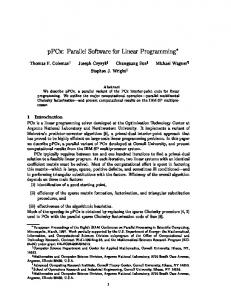
Figure 1. Application logic and domain logic layers of the presented language
Figure 2. Hyper-linking the application with the domain
1. Programming at the requirements level In Domain-Specific Modelling, models become the de-facto code. This approach of shifting the level at which programming is done allows for achieving very significant raise in productivity (as pointed out in [3]). This is, though, achieved at a cost of learning and maintaining self-designed modelling languages. We thus would like to design a generalpurpose modelling language suitable for various problem domains. At the same time, this language should be understandable by domain experts (especially including non-IT specialists) who participate in specifying requirements for software systems. For the above reasons, we will base our design of a requirements-level programming language on a widely accepted approach to specifying functional requirements. We will apply use cases (see [16] for the initial idea) which are also part of the widely used Unified Modelling Language (see [17] for the official specification). Use cases are normally not seen as first-class modelling artifacts and do not normally participate in the model transformation paths mentioned in the previous section. This is because the use case representations have quite vague semantics and approaches to clarify this are sparse (see [18] for one of the few). In [19] there was proposed an extension to the use case model which clarifies the control flow of use cases and facilitates its automatic transformation into other modelling artifacts. The general idea of requirements-level programming is presented in Figure 1. The use case representations define flows of user-system interactions which specify the application logic of the system. This application logic uses terms and phrases specific for a given problem domain. These terms (domain elements) and phrases (domain-specific actions) constitute the domain logic with appropriately defined processing algorithms.
Figure 3. Initial use case model of the case study
Figure 4. Scenario of the “Show owned course list” use case
Figure 5. Scenarios of the “Add new course” use case
What is important, the domain logic (cf. domain-specific languages) is declared in a language which does not depend on any specific domain. This way we result in a generalpurpose language where the application logic is precisely separated from the domain logic. It can be noted that the specifications at the application logic level can be easily applied to any other problem domain by substituting terms and phrases. This is illustrated in an example in Fig. 2. There we can see two identical fragments of application logic applied to two different problem domains with different processing algorithms. The above presented criteria for a programming language at requirements level are
Figure 6. Structure of the initial requirements model
met by the Requirements Specification Language (RSL, see [20] for full specification) developed within the ReDSeeDS project (www.redseeds.eu). The language allows for specifying use case representations, defining flows of events and associating terms used in these events with a central domain vocabulary. We will illustrate the language through a case study example. In Figure 3 we can see a fragment of the use case model of a Campus Management System (CMS). This model follows standard use case modelling principles with the exception of two �invoke� relationships. This type of relationship substitutes the ambiguous �extend� and �include� relationships (see [21]). Figures 4 and 5 show the details of use case representations. The presented scenarios are written in a simple subject-verb-object (SVO) grammar. They also show how the �invoke� relationship is weaved into the flow of events. In Figure 5 we can see two scenarios with their flow being controlled by two conditions (=� cond). It can be also noted that the objects in the SVO are either elements of the problem domain (e.g. “student”) or the user interface (e.g. “student form”). This distinction will help in generating code as described in the further sections. The SVO sentences are linked to a central vocabulary which is presented in Figure 6 (left). Every object in a sentence has an associated domain element (notion) in the vocabulary. Obviously, objects in different sentences can point to the same domain element. This way, the whole specification is coherent with scenarios written in a uniform terminology. At the same time, the vocabulary offers space for specifying the domain logic (placed under domain phrases like “save course”). It can be noted, that an additional activity from the requirements specifiers it to divide both the use case model and the domain vocabulary into packages. These packages will be used to structure the final code generated from requirements, as presented in the next section.
2. From requirements to code In order to be able to generate code from the above presented requirements models we need to assign operational semantics to them. This would mean that each of the RSL constructs would have their meaning explained in the code execution environment. We will supply this meaning by specifying automatic rules for transforming these constructs into Java-like code. This way, the RSL operational semantics will be transformed onto Java runtime semantics. The following list presents the most important rules (some rules were omitted for brevity), concentrating on the elements defining the application logic.
Figure 7. Generated general structure of the case study system (rules 1-3)
1. Package transformation. Every package in the requirements model is transformed into a package in Java. The packages are divided into the application logic layer (use case packages) and the domain logic layer (notion packages). In addition, a single package for user-interface-related operations is generated. 2. Use case transformation. Every use case is transformed into a public class (with appropriately concatenated name) in the associated application logic layer package. The class name is derived from the use case name (“camel case”) with the “C” (Controller) prefix. 3. Notion transformation. Every notion is transformed into a public class (with appropriately concatenated name) in the associated domain logic package. The class name is derived from the use case name (“camel case”) with the “M” (Model) prefix. 4. Phrase transformation. Every verb phrase in the domain model is transformed into an operation in the class generated either from the containing notion or from the use cases that use this phrase. The name of the operation is a concatenation of words of the phrase. The detailed rules are as follows.
Figure 8. Illustration of rules 1-3 applied to the CourseManagement package
Figure 9. Generated classes and their operations (rules 2-4) for the StudentManagement package
(a) Verb phrase used in an SVO sentence where an actor is the subject and a domain element is the direct object is generated into an operation of the class generated from the use case containing the SVO sentence. (b) Verb phrase used in an SVO sentence where the system is the subject and a user interface element is the direct object is generated into an operation of the class within the user-interface-related package. (c) Verb phrase used in an SVO sentence where the system is the subject and a domain element is the direct object is generated into an operation of the class generated from the containing notion.
Figure 10. Generated dynamic code for “Show owned course list” (rules 5a-5c)
Figure 11. Sequence diagram explaining code from Fig. 10
5. Scenario transformation. Every set of scenarios for a use case is transformed into code within the methods of the class generated from this scenario. The detailed rules are as follows. (a) Code of the class generated from a use case contains methods associated with operations generated according to rule 4a. (b) Every method in the above class contains code generated from sentences that follow an SVO sentence from rule 4a and finish at the next such sentence. (c) Inside the above method, there are generated method calls. For an SVO sentence from rule 4b, a call to the method realising a user-interface-related operation is generated. For an SVO sentence from rule 4c, a call to the method realising a domain logic operation is generated. (d) Alternatives in scenarios are transformed into conditional instructions (“if”). For each of the alternative scenarios, a branch in the conditional instruction is generated. The branching is done by detecting the value returned by the method call generated from the last SVO sentence before the alternative in the scenario. The above rules are illustrated in the case study example. Figures 7 to 13 show the structure and dynamics of the code generated from the requirements model presented in
Figure 12. Generated dynamic code for “Add new course” (rules 5a-5d)
the previous section. Figure 7 presents the application of rules 1 to 3. It shows the packages and classes generated rom the requirements model structure shown in Figure 6. In Figure 8 we can see some more details for the part of the system that participates in the functionality of “Course management”. This UML class diagram shows three layers with the “C” classes defining the application logic (controllers) for the appropriate use cases. The “M” classes are associated with the appropriate “C” classes and form the domain logic (models) of the system. Also the “V” (view, or user interface) classes are generated according to the scenarios and associated with appropriate controllers. In summary, each of the packages of the application logic layer has classes generated from use cases (e.g. the “Edit course” use case is transformed into the CEditCourse class). Similar rule was applied to the domain logic layer (e.g. the “course list” notion transformed into the MCourseList class). More detailed example for rules 2, 3 and 4 is presented in Figure 9. There we can see the classes associated with the “Student management” functionality. In this class diagram we have revealed also the details of the class operations. It can be noted that the operations of classes CEditStudent and CRegisterNewStudent are generated according to rule 4a. Moreover, we can see the MStudent class where its operations are compliant with the rule 4c. Finally, there are presented three “V” classes that define the user interface frames. Their operations were generated according to rule 4b. The above classes and their operations are used to fulfill the scenario presented in Figure 5. Figures 10 and 12 show the most important parts of code of two “C” classes. This code has been generated using all five rules. Thus, it includes also the dynamic part (the method contents). The associated UML interaction (sequence) diagrams explain how
Figure 13. Sequence diagram explaining code from Fig. 12
this code is equivalent to scenarios presented in Figures 4 and 5. Comparison of these four figures should facilitate understanding of the set of rules 5a-5d. It can be noted that in order to generate all the code details (like e.g. the call/method signatures), some additional markings in the requirements model and additional rules would need to be applied. These simple rules were omitted due to limited space.
3. Software evolution as requirements evolution Having the automatic code generation mechanisms presented in the previous section we can now define a schema for software evolution. As postulated in the introduction, the schema is driven by changes in requirements. This is illustrated in Figure 14. It shows two iterations in an evolutionary software lifecycle. In the first iteration, the requirements (describing the application logic RAL1 and the domain logic RDL1 ) are specified and appropriate code generated. According to what was demonstrated in the previous section, the application logic code CAL1 can be generated fully, but the domain logic code CDL1 can be generated partially (only the class structure, methods and signatures). In the second iteration, both the application logic and domain logic requirements change (δRAL and δRDL ). After the change, the application logic code CAL2 can be generated
Figure 14. General schema for software evolution
Figure 15. Updated use case model of the case study
automatically, and no additional effort is needed. However, there remains a crucial issue of determining changes to the domain logic code CDL2 . We would like to know which methods in the partially generated code CDL2 need updates by programmers and to what extent. This can be done by examining changes in domain logic requirements δRDL . It can be noted that in order to examine these changes (especially in large systems with vast requirements specifications) we need a tool which compares two requirements specifications and shows the δ. By tracing this delta into code, the methods needing rework can be indicated very precisely (δCDL ). Let us now examine the schema we have sketched above, within our case study example. The changed requirements are presented in Figures 15 and 16. The first diagram shows the updated use case model, with added use cases highlighted. The second diagram presents changes made to the representation of one of the use cases. These changes also indicate additional user interface functionality necessary for fulfilling this additional application logic. Namely, in this new version, the system needs to “display again” the student form which assumes also displaying an additional error message and a request to correct the student data.
Figure 16. Updated scenario of the “Show owned course list” use case
Figure 17. Updated structure of the case study system
Based on these changed requirements, code has been re-built. Its new version now has an updated structure shown in Figure 17. It can be noted that the structure has been extended appropriately to the extension in the use case set and the necessary domain elements (notions). New classes (CShowStudentList, CUpgradeStudentStatus) have been added, and the existing classes have been modified (only the relevant part of the system was shown for brevity). By comparing Figures 9 and 17 it can be easily determined which additional operations have been created for the new logic. Figure 18 show updates made to the code of the CRegisterNewStudent class. Changes can be easily determined by comparing this with Figure 12. It can be noted that the code has been updated by calling the additional “displaysAgain” method. In Figure 19 we can additionally see an excerpt of the code generated within the presentation layer. This code forms an event handler that reacts to pressing the “OK” button on the “student form” window, as shown in Figure 20. The code for showing the window and the event handler could also be generated automatically. This was done according to additional
Figure 18. Updated application logic code
Figure 19. Sample code of the presentation layer class
Figure 20. Example window generated automatically from the requirements
rules, which were out of scope of this paper. This shows that a significant portion of the application could be generated directly from the use cases and their scenarios. The application logic code (e.g. the “selectsOK” method) presented in Figure 18 can be generated using the transformation rules introduced in this paper. However, the
domain logic code (e.g. method “validates” in CStudent). Thus, we need a mechanism to determine code which needs rework. This can be done by examining code in Figures 12 and 18. The difference is quite obvious and the additional methods can be easily indicated. Also, the methods that can be retained are easily detected.
4. Conclusion and future work The most important aim of this work was to demonstrate that general-purpose requirements models can have operational (runtime) semantics and this semantics can be used to achieve high levels of automation in code evolution. As the presented case study shows, our approach automates to significant extent the transition from requirements written in constrained natural language to code. We have demonstrated that the presented semantics allows for generating Java code within the application logic layer. It is important to note that the presented RSL language fulfills the requirements postulated in [22]. Its understandability to the users was validated in the industrial context and the results presented in [23]. In this paper we have shown that RSL is also precise enough to control code generation. Thus we can claim that the new approach, together with the ReDSeeDS tool, constitute a powerful mean of support for the software developers. The main benefit is that the developers can quickly see the consequences of changes to application logic on the domain logic. This ‘diff’ can be determined for even a yet not existing code right after the requirements are ready. The differences are illustrated by instantly showing places in the domain-specific code where code rework is needed. Another important benefit is that the system refactors the code automatically based on the changed scenarios and domain notions. The developers have clear pointers, as to which methods should be changed (extended, combined, split, etc.). This is clearly shown by comparing visually with the previous version. A software development organisation can base its software lifecycle around a repository of RSL-based requirements models. Within this repository, different variants of the same system (produced in different iterations) can be stored. The repository can also contain models for other systems, produced in different domains. It can be noted that after conducting several projects, a development organisation obtains a powerful repository of reusable artifacts. These artifacts can be reused by building new versions, but also a wider (cross-domain, cross-system) reuse is possible. This can be done by merging use cases and associated code. Requirements written in RSL offer specific solutions to specific problems. However, it can be noted that RSL models can be also treated as certain application logic patterns. If we detach the application logic from the specific domain we obtain a generalised model which can be treated as a pattern for visible functionality of software (see. also Figure 2). This seems to be an interesting research direction and has been recently elaborated in [24]. Another interesting direction is to introduce into RSL certain constructs that would allow for specifying domain-specific elements in more detail. By combining with the pattern approach, this direction would allow for constructing applications based on pre-defined domain specifications and associated patterns of application-logic functionality. The new domain-specific element of RSL could include an algorithmic language for specifying domain logic processing (as opposed to application logic processing offered already by RSL). Also, certain notation could be introduced for repre-
senting domain-specific data objects (structure of the domain). This could be combined with possible integration of RSL with the existing domain-specific languages. Domainspecific languages could be plugged-in at the domain logic level and substitute the above mentioned domain-specific elements of RSL. References [1] [2] [3] [4] [5] [6] [7] [8] [9] [10]
[11] [12]
[13] [14] [15] [16] [17] [18] [19]
[20]
[21] [22] [23] [24]
Miller, J., Mukerji, J., eds.: MDA Guide v. 1.0.1, omg/03-06-01. Object Management Group (2003) Stahl, T., Völter, M.: Model Driven Software Development: Technology, Engineering, Management. Wiley (2006) Kelly, S., Tolvanen, J.P.: Domain Specific Modeling: Enabling Full Code Generation. WIley (2008) Clements, P., Northrop, L.: Software Product Lines: Practices and Patterns. Addison Wesley Professional (2002) Greenfield, J., Short, K.: Software Factories. Assembling Applications with Patterns, Models, Frameworks and Tools. Wiley, Indianapolis, Indiana (2004) Mens, T., Demeyer, S., eds.: Software Evolution. Springer Verlag (2008) Ernst, N.A., Mylopoulos, J., Wang, Y.: Requirements evolution and what (research) to do about it. Lecture Notes in Business Information Processing 14 (2009) 186–214 Nuseibeh, B.: Weaving together requirements and architectures. IEEE Computer 34(3) (2001) 115–117 Sutcliffe, A.: On the inevitable intertwining of requirements and architecture. Lecture Notes in Business Information Processing 14 (2009) 168–185 Barber, K.S., Graser, T.J., Grisham, P.S., Jernigan, S.R.: Requirements evolution and reuse using the systems engineering process activities (sepa). Australian Journal of Information Systems 7(1) (1999) 75–97 Special Issue on Requirements Engineering. Zowghi, D., Gervasi, V.: On the interplay between consistency, completeness, and correctness in requirements evolution. Information and Software Technology 45 (2003) 993–1009 Moon, M., Yeom, K., Chae, H.S.: An approach to developing domain requirements as a core asset based on commonality and variability analysis in a product line. IEEE Transactions on Software Engineering 31(7) (2005) 551–569 ´ Smiałek, M.: From user stories to code in one day? Lecture Notes in Computer Science 3556 (2005) 38–47 XP 2005. de Boer, R.C., van Vliet, H.: On the similarity between requirements and architecture. Journal of Systems and Software 82(3) (2009) 544 – 550 Du Bois, B., Demeyer, S.: Accommodating changing requirements with EJB. Lecture Notes in Computer Science 2817 (2003) 152–163 Jacobson, I., Christerson, M., Jonsson, P., Overgaard, G.: Object-Oriented Software Engineering: A Use Case Driven Approach. Addison-Wesley, Reading (1992) Object Management Group: Unified Modeling Language: Superstructure, version 2.2, formal/2009-0202. (2009) van den Berg, K.G., Simons, A.J.H.: Control flow semantics of use cases in UML. Information and Software Technology 41(10) (1999) 651–659 ´ Smiałek, M., Bojarski, J., Nowakowski, W., Ambroziewicz, A., Straszak, T.: Complementary use case scenario representations based on domain vocabularies. Lecture Notes in Computer Science 4735 (2007) 544–558 ´ Kaindl, H., Smiałek, M., Svetinovic, D., Ambroziewicz, A., Bojarski, J., Nowakowski, W., Straszak, T., Schwarz, H., Bildhauer, D., Brogan, J.P., Mukasa, K.S., Wolter, K., Krebs, T.: Requirements specification language definition. Project Deliverable D2.4.1, ReDSeeDS Project (2007) www.redseeds.eu. ´ Smiałek, M., Bojarski, J., Nowakowski, W., Straszak, T.: Scenario construction tool based on extended UML metamodel. Lecture Notes in Computer Science 3713 (2005) 414–429 ´ Smiałek, M.: Accommodating informality with necessary precision in use case scenarios. Journal of Object Technology 4(6) (2005) 59–67 Mukasa, K.S., Jedlitschka, A., Graf, C., et al.: Requirements specification language validation report. Project Deliverable D2.5.1, ReDSeeDS Project (2007) ´ Ambroziewicz, A., Smiałek, M.: Application Logic Patterns - Reusable Elements of User-System Interaction Lecture Notes in Computer Science 6394 (2010) 241–255