Hindawi Publishing Corporation Mobile Information Systems Volume 2016, Article ID 8163893, 14 pages http://dx.doi.org/10.1155/2016/8163893
Research Article A Framework and Mathematical Modeling for the Vehicular Delay Tolerant Network Routing Mostofa Kamal Nasir,1 Rafidah Md. Noor,1 Mohsin Iftikhar,2 Muhammad Imran,3 Ainuddin Wahid Abdul Wahab,1 Mohammad Reza Jabbarpour,1 and R. H. Khokhar2 1
Faculty of Computer Science and Information Technology, University of Malaya, Kuala Lumpur, Malaysia School of Computing and Mathematics, Charles Sturt University, Wagga Wagga, NSW, Australia 3 College of Computer and Information Sciences, King Saud University, Riyadh, Saudi Arabia 2
Correspondence should be addressed to Mostofa Kamal Nasir;
[email protected] Received 21 August 2015; Revised 3 February 2016; Accepted 19 April 2016 Academic Editor: Ting Yang Copyright © 2016 Mostofa Kamal Nasir et al. This is an open access article distributed under the Creative Commons Attribution License, which permits unrestricted use, distribution, and reproduction in any medium, provided the original work is properly cited. Vehicular ad hoc networks (VANETs) are getting growing interest as they are expected to play crucial role in making safer, smarter, and more efficient transportation networks. Due to unique characteristics such as sparse topology and intermittent connectivity, Delay Tolerant Network (DTN) routing in VANET becomes an inherent choice and is challenging. However, most of the existing DTN protocols do not accurately discover potential neighbors and, hence, appropriate intermediate nodes for packet transmission. Moreover, these protocols cause unnecessary overhead due to excessive beacon messages. To cope with these challenges, this paper presents a novel framework and an Adaptive Geographical DTN Routing (AGDR) for vehicular DTNs. AGDR exploits node position, current direction, speed, and the predicted direction to carefully select an appropriate intermediate node. Direction indicator light is employed to accurately predict the vehicle future direction so that the forwarding node can relay packets to the desired destination. Simulation experiments confirm the performance supremacy of AGDR compared to contemporary schemes in terms of packet delivery ratio, overhead, and end-to-end delay. Simulation results demonstrate that AGDR improves the packet delivery ratio (5–7%), reduces the overhead (1–5%), and decreases the delay (up to 0.02 ms). Therefore, AGDR improves route stability by reducing the frequency of route failures.
1. Introduction Recent advancements in sensing, computing, wireless communication, and networking technologies have led to the emergence of internet of vehicles (IoV) paradigm [1] which will not only complement existing applications but also introduce plethora of novel applications and services (e.g., collision avoidance, safety, intelligent traffic monitoring and prediction, multimedia streaming, infotainment, and ehealth [2]). IoV primarily relies on vehicular ad hoc networks (VANETs) [3] for autonomous communication among vehicles on the road and traffic management. A routing protocol in VANET is important to find the data forwarding path and also to maintain connection especially in sparse environment for the successful completion of data delivery [4, 5]. In VANETs, the state-of-the-art protocols exploit geographic
positions of neighbor nodes instead of physical addresses [6, 7] as most of the modern vehicles are equipped with number of devices such as sensors, On Board Units (OBU), Navigation System (NS), and Geographic Positioning System (GPS) [8]. The prime concern of routing is to discover and maintain a reliable communication path that requires maintaining up-to-date information about neighboring nodes which can be acquired through either continuous flooding of control packets or transmission of beacon messages. However, sparse node density and frequent high-speed mobility result in network partitioning and intermittent connectivity [9, 10] which makes it difficult for the packets to be delivered from source to the destination [11]. In such dynamic environments, adaptive Delay Tolerant Network (DTN) routing protocols are necessary which can discover an appropriate next-hop
2 forwarder node (neighbor) on the path towards the destination. This selection should be made in such a way that improves data delivery probability with reduced delay and balances the network overhead [12]. To cope with the problems of network partitioning and frequent disruption, a novel Adaptive Geographical DTN Routing (AGDR) protocol is proposed. AGDR employs mobility features such as GPS, NS, and Direction Indicator Light (DIL) information. Specifically, AGDR exploits the node position, speed, current direction, and predicted future direction. To the best of our knowledge, AGDR is the first adaptive DTN routing protocol that exploits DIL information. The next-hop selection process is used to select the intermediate node and forward the packet to the desired destination. The performance of AGDR is validated through simulation experiments. Simulation results demonstrate the effectiveness and efficiency of AGDR compared to contemporary schemes. To develop an adaptive routing protocol for Delay Tolerant Network in vehicular environment, we need to propose a novel framework which is easy to demonstrate, accessible, and detailed enough to understand. The basic architecture describing the framework is composed of several parts with distinct predefined functions. Each layer is capable of receiving the input and sending the output to below or upper layer. The advantages and viability of this approach are effectively used in many existing systems in present days such as TCP/IP family of protocols [13]. Moreover, this simplification provides a better understanding. It is easy for development. Each module of the framework is different in terms of its functionality and semantics. To define the specialized validation routines on each module for analysis, specific properties of the framework based on characteristics of its essential components are being defined. The framework is sort of a model that can be represented with several independent modules which communicate via simple interfaces. The remainder of this paper is organized as follows. Background and related works are discussed in Section 2. Section 3 elaborates adaptive framework for the vehicular DTN (VDTN). The details of AGDR are presented in Section 4. Section 5 includes the experiment setup, results, and analysis. Conclusions are made in Section 6.
2. Background and Related Work Routing in ad hoc networks has been extensively investigated. However, conventional ad hoc routing protocols may not be suitable for VANETs due to unique characteristics such as high-speed frequent mobility and sparse topology especially in urban environments which leads to intermittent connectivity. Therefore, VANETs are likely to experience less delivery probability, high error rates, and long delays as end-to-end route may not exist at a certain time [14]. Some recent approaches such as [15] rely on mobile crowd sensing for traffic prediction. However, our objective in this work is different and only relies on in-vehicle sensors. Most of the conventional VANET protocols assumed a fully interconnected network with end-to-end path which may not be practical in sparse topology environments.
Mobile Information Systems Geographic routing protocols are considered to be more appropriate for highly dynamic environments such as VANET. These protocols are generally categorized into DTN and non-DTN [16]. The latter is only suitable for high density networks that can provide reliable network connectivity as alternative paths are available. On the other hand, VDTN protocols are specifically designed to cope with network partitioning and disconnections mainly caused due to frequent mobility and sparse topology [17]. Therefore, packet delivery in VDTN is more crucial than delay as these networks are characterized by inadequate transmission opportunities and intermittent connectivity. The focus of this work is on VDTN [18]. As the direct connection with a node in VDTN may not be possible due to limited transmission range of road side units (RSUs), therefore, vehicles may serve as an intermediate node to relay packets [19]. However, in such a case, end-toend path may not exist for a certain time and intermediate nodes may have to buffer data [20] until a forwarding opportunity arises. However, these forwarding opportunities are of very short duration with high link error rates. The prime objective of VDTN protocols in such circumstances is to maximize data delivery probability while minimizing end-to-end delay [21]. Most of the existing researches have adopted conventional routing protocols with the assumption of a fully connected VANET that can provide end-to-end path. However, such protocols may not be suitable for VDTN especially for nonurban environments where connectivity is intermittent, end-to-end route may not exist for a certain time, or the network is partitioned [22]. Moreover, proactive approaches such as [23] to predict prepartitioning may not be practical in context of VANET due to continuous frequent topology changes. On the other hand, uncontrolled movement of vehicular nodes makes it difficult to restore ondemand connectivity [24]. Therefore, an adaptive framework for VDTN routing is indispensable. Most of the existing routing protocols are unable to handle frequent network disconnection. However, few protocols such as Vehicle-Assisted Data Delivery (VADD) aimed at improving routing in disconnected vehicular networks in urban scenarios [25] where it uses carry-and-forward approach until a relay is found. Therefore, it takes long time to deliver packets in low density networks. GeoOpps is a DTN routing algorithm that exploits the availability of information from the NS in order to opportunistically route a data packet to a certain geographical location [22]. Nonetheless, these protocols are not suitable for partitioned networks in urban scenario. GPSR is an opportunistic protocol that requires only the location information. It is more suitable for high density networks with minimal probability of encountering perimeter mode and hence delays. It uses digital maps for improved topology view of the network but still reverts to perimeter mode if relays are not found. It increases transmission failures in a disconnected network. Both VADD and GeoOpps have provisions for disconnections but still face challenges of inducing higher delays due to their carryand-forward strategy on a single lane freeway mode and lack of utilization of vehicle connections on the opposite lanes.
Mobile Information Systems Moreover, none of these protocols employ the knowledge of the DIL information [26] of each vehicle in the network. To address the main challenge of higher packet deliveries during disconnections, new proposals are required as most existing protocols do not consider continuously changing network topology and thus are not suitable for sparse networks with intermittent connectivity. The performance of DTN routing protocol depends on vehicle density and mobility model of the network, therefore, the vehicular traffic model is also important. Vehicle movement (e.g., location, velocity, and acceleration) is represented through mobility models as it affects network connectivity. These models are frequently used for simulating new routing protocols. An efficient routing technique in VANETs, specifically in sparse environment, impacts enhancing communication performance of data transmission to the target destination, reduces the packet overhead, and maximizes data delivery in a minimum time. The prime concern is to discover and maintain a reliable communication path for the vehicular network which requires maintaining up-to-date information about neighbor nodes which can be acquired through either continuous flooding of control packets or transmission of beacon messages [27, 28]. Sparse node density and frequent high-speed mobility result in network partitioning and intermittent connectivity which makes it difficult for the packets to be delivered from source to the destination. In such dynamic environments, an adaptive framework and VDTN routing protocols are necessary which can discover an appropriate next-hop forwarder node (neighbor) on the path towards the destination. This selection should be made in such a way that improves data delivery probability with reduced delay and balances the network overhead.
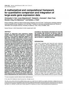
3. Framework for the Adaptive VDTN This section presents a novel framework for OBU in VDTN. The framework consists of four main modules, that is, sensing unit, processing unit, node discovery unit, and dedicated short-range communication (DSRC) standardized by IEEE 802.11p. Figure 1 depicts the proposed framework and details of each unit are described in the following. 3.1. Sensing Unit. The sensing unit collects data from different sensors such as accelerator, break, and GPS and forwards it to the application layer for onward processing which further passes it to network layer. On-board diagnostics standard interface [29] can be used for collecting data from sensors and passing it to OBU. For example, brake sensor immediately detects and transmits the corresponding information to the speed control and monitor unit in OBU. 3.2. Processing Unit. The processing unit receives data from sensors and processes it for decision-making. For example, data from GPS and digital map can be used to determine vehicle direction. Similarly, direction of the vehicle can be predicted based on the digital map and DIL information. 3.3. Node Discovery Unit. This unit is responsible for discovering an appropriate neighbor based on node geographic
3 position, vector information, and predicted future direction. It uses HELLO messages to discover neighboring nodes. The next-hop selection algorithm is used to find an appropriate neighbor for data forwarding. 3.4. DSRC/WAVE Control Unit. Federal communication commission has exclusively allocated 75 MHz bandwidth from 5.9 GHz spectrum for vehicle-to-vehicle (V2V) and vehicle-to-infrastructure communication.
4. Mathematical Analysis of Performance Metric for VDTN This section presents mathematical analysis for the calculation of performance metrics such as routing overhead, endto-end delay, and message propagation for VDTN. 4.1. Mathematical Analysis of Routing Overhead in VDTN. In VDTN, routing overhead primarily depends on the number of neighboring nodes and the number of hops where the latter refers to the count of intermediate nodes on the path from source to the destination [30]. This work uses probabilistic method for calculating routing overhead. Let us assume that 𝑛 nodes are randomly distributed in an area of 𝑎 × 𝑏 square meter. The transmission range of each node is assumed to be 𝑙; therefore, the network dimensions are 𝑎 and 𝑏 where 𝑎, 𝑏 ≫ 𝑙. 𝑆 and 𝐷 are source and destination nodes. The probability 𝑝 of a node 𝐴 to be within transmission range of 𝑆 can be calculated by 𝑝=
𝜋𝑙2 . 𝑎𝑏
(1)
The probability of having 𝑚 neighbors (from 𝑛 − 1) of 𝑆 can be calculated through the following equation: 𝑃𝑀 (𝑚) = (
𝑛−1 𝑚 𝑛−1−𝑚 ) 𝑝 (1 − 𝑝) , 𝑚
(2)
where 𝑚 is a binomial random variable and 𝐸[𝑚] represents the average number of neighbors for any node in the network. We can find the probability distribution function (PDF) by interchanging the variable 𝑢 = 𝑙2 from the arbitrary variables 𝑧 and 𝑤. Since 𝑧 and 𝑤 are independent, the PDF of 𝑢 can be calculated by 𝑓𝑈 (𝑢) = 𝑓𝑍 (𝑧) ∗ 𝑓𝑊 (𝑤) .
(3)
In (3), ∗ stands for the convolution and the PDF of 𝑟 can also be determined. From (3), we can calculate the expected number of hops, that is, 𝐸[𝑙] and 𝐸[𝑘]: 𝐸 [𝑟] = ∫ 𝑥𝑓𝑟 (𝑥) 𝑑𝑥, 𝐸 [𝑘] = [
𝐸 [𝑟] ], 𝑙
(4) (5)
where 𝑑 is the node transmission range. We are interested to find the average number of overhead packets. Routing
4
Mobile Information Systems
GPS
Break press
Accelerator
DIL info
Sensor Direction and location Control and monitor
Speed control and monitor
Application layer Processing unit
Preloaded digital map
Diverse application
Network layer Node discovery WAVE management entity
Next-hop selection
TCP/UDP
WAVE short message protocol
IPv6
Destination node ID Logical link control Facilities
802.11p
Upper MAC layer management entity
Header
IP header
Data packet overview
WAVE upper MAC layer
IP header Data packet
Lower MAC layer management entity
WAVE lower MAC layer
MAC sublayer Physical layer
Physical layer management entity
Tx
Communication status
Rx
Figure 1: Framework for adaptive VDTN routing.
overhead refers to the number of control packets (route request and reply) propagated throughout the network. To void redundancy, request ID and sender address of route request are considered. The route request packet will propagate to the depth of 𝐸[𝑑]. Figure 2 depicts two nodes 𝐴 and 𝐵 with (𝑛 − 1)𝑝 neighbors on average. We denote the transmission range of 𝐴 and 𝐵 as 𝑆𝐴 and 𝑆𝐵, respectively, and the shared area as 𝑆𝐴 ∩ 𝑆𝐵. If 𝑅 is the distance between 𝐴 and 𝐵, then the intersection can be found by INTC (𝐴, 𝐵) = 4 ∫
𝑑
𝑅/2
√𝑟2 − 𝑥2 𝑑𝑥.
(6)
As the average route request passes through the depth 𝐸[𝑘] while not reaching the destination. From (4), we can find the neighbors for the 𝐸[𝑘]th level as follows: 𝐸𝐸[𝑘] =4 4
𝐸[𝑘]−1
(7)
× 3𝐸[𝑘]−1 [∑ [(𝑛 − 1 − 𝑖) − ∑ 𝑁𝑗 ] 𝑝 ⋅ 𝐶𝑖 ] . 𝑗=1 [𝑖=2 [ ] ] The expected number of total route request broadcasts can be calculated by
Mobile Information Systems
5
A
𝐸[𝑘]
B
𝐸 [Broadcasts] = ∑ 𝑁𝑖 ,
(8)
𝑖=1
R
where 𝑁𝑖 denotes the number of neighbors in level 𝑖 that are connected to the next level. As mentioned earlier, routing overhead is based on route request and route reply while (8) only represents the former. Therefore, the average number of route replies from destination to the source can be found as follows:
l
𝐸 [reply] = (𝑛 − 4) 𝑝 + 2.
In general, the route reply of a message can be written as follows:
Figure 2: A simple VANET with two nodes.
𝐸 [𝑘] { { {𝐸 [𝑘] + 2 (𝑛 − 𝐸 [𝑘] − 2) 𝑝 𝐸 [reply] = { { {𝐸 [𝑘] + INT ( 𝐸 [𝑘] (𝑛 + 𝐸 [𝑘] + 2) 𝑝 + (𝑛 − 𝐸 [𝑙] − 2)) 0.41𝑝 2 {
From (9) and (10), we can calculate the routing overhead. 4.2. Mathematical Analysis of End-to-End Delay in VDTN. Let us assume that the PDF of the catch-up time 𝑇𝑐 , ∫ 𝑇𝑐 (𝑡) is given by the following equation: 𝑃 (𝑋 (𝑡) ≤ 𝑥 | 𝑇𝑐 = 𝑡) fl 𝑃𝑋(𝑡) (𝑥) = 𝑃 (𝑋 (𝑡) ≤ 𝑥) .
(11)
From (11), we find that the PDF of 𝑋(𝑡) is conditional to 𝑇𝑐 , ∫ 𝑋(𝑡) | 𝑇𝑐 (𝑥𝑐 | 𝑡). After that, multiplying ∫ 𝑋(𝑡) | 𝑇𝑐 (𝑥𝑐 | 𝑡) by the PDF of 𝑇𝑐 , ∫ 𝑇𝑐 , we find the combined PDF [31]. When 𝑡 = 0, two nodes should be within the transmission range of each other. Hence, the marginal cumulative distribution function (CDF) goes through the following distribution: 1 − 𝑒−𝜆𝑥 , 1) . 𝑃 [𝑋𝑐 ≤ 𝑥 | 𝑋𝑐 ≤ 𝑙] = min ( 1 − 𝑒−𝜆𝑙
if 𝑥 > 𝑙 if 𝑥 ≤ 𝑙.
𝑡max
𝑡=0
𝐹𝑋(𝑡),𝑇𝑐 (𝑥, 𝑡) 𝑓𝑇𝑐 (𝑡) 𝑑𝑡,
𝐸 [𝑘] is odd.
(13)
(14)
where 𝑇max is the maximum possible duration for the distance 𝑥max (𝑡max = 𝑥max /Vmin ).
(10)
The combined CDF 𝐹𝑋(𝑡),𝑇𝑐 (𝑥, 𝑡) can be alias to 𝐹𝑋1 ,𝑇1 (𝑥, 𝑡) and its PDF to 𝑓𝑋1 ,𝑇1 (𝑥, 𝑡) as they are based on the dependent probability of distance and time. A normal dependent CDF for the total 𝑛 + 1 node is 𝐹𝑋𝑛+1 ,𝑇𝑛+1 (𝑥, 𝑡) = (𝐹𝑋𝑛 ,𝑇𝑛 ∗ 𝑓𝑋1 ,𝑇1 ) (𝑥, 𝑡) .
(15)
The data pocket that reached final destination 𝐹𝑇𝑑 (𝑡) can be found by 𝐹𝑇𝑛 (𝑡) fl 𝐺𝑡,𝑛 (𝑥max ) .
(16)
From (16), end-to-end delay can be determined as follows: ∞
(17)
𝑛=0
(12)
To simplify calculations, we change this function 𝐹𝑋(𝑡) in the 𝑥 coordinates by the transmission range of 𝑙 for data transmission from one node to another. The radio propagation covering distance 𝑙 for 𝑋𝑐 can be found through the CDF of 𝐹𝑋(𝑡) which can be calculated from the following equation: 𝐹𝑋𝑐 (𝑥) = ∫
𝐸 [𝑘] is even
𝐹𝑇𝑑 (𝑡) = ∑ 𝐹𝑇𝑑 (𝑡) .
But, when 𝑡 > 0, the joint CDF can be written as follows: {𝐹𝑋(𝑡) (𝑥 − 𝑙) 𝐹𝑋(𝑡),𝑇𝑐 (𝑥, 𝑡) = { 0 {
(9)
4.3. Mathematical Analysis of Message Propagation for VDTN. In most cases, data packets have a limited lifetime and they are discarded once their lifetime is expired. In this subsection, we calculate the message propagation probability of VDTN. The total number of nodes joining the network of a road section ℎ𝑗𝑘 is considered as a static variable and related stochastic process is modeled as a Poisson distribution [32]. The probability density function of the network at road ℎ𝑗𝑘 is thus given by the following: ℎ 𝑃𝑧 𝑗𝑘
(𝑡) =
(𝜆 𝑗𝑘 𝑡) 𝑧!
𝑧
𝑐−(𝜆 𝑗𝑘 𝑡) ,
(18)
where 𝜆 𝑗𝑘 represents the mean arrival rate at road ℎ𝑗𝑘 and 𝑧 represents the number of arrivals in time interval 0 to 𝑡. For calculation simplicity, we considered a part of the roadway network in our analysis as shown in Figure 3.
6
Mobile Information Systems
hi
hij R
veh1 l 𝜃
M
hj
hjk
hk
m
Figure 3: An intersection in a road network.
Figure 3 shows roads ℎ𝑖𝑗 and ℎ𝑗𝑘 with corresponding intersections 𝐼𝑖 with 𝐼𝑗 and 𝐼𝑗 with 𝐼𝑘 . The roads ℎ𝑖𝑗 and ℎ𝑗𝑘 form an angle which is denoted by 𝜃. 𝑅 and 𝑀 are the points at roads ℎ𝑖𝑗 and ℎ𝑗𝑘 , respectively, which are at distance 𝑙 from intersection 𝐼𝑗 . At time 𝑡 = 0, a vehicle veh1 travelling with speed 𝑉1 is at distance less than 𝑙 heading towards intersection 𝐼𝑗 . In this case, we concentrate on two basic scenarios to propagate information. First is the probability 𝑝1ℎ𝑖𝑗 ℎ𝑗𝑘 to transmit the information directly from vehicles on ℎ𝑖𝑗 to vehicles on ℎ𝑗𝑘 . Second is the probability 𝑝2ℎ𝑖𝑗 ℎ𝑗𝑘 , where an informed vehicle veh1 from ℎ𝑖𝑗 turns into ℎ𝑗𝑘 . The probability 𝑝ℎ𝑖𝑗 ℎ𝑗𝑘 depends on the portion of the traffic arrival rate from road ℎ𝑖𝑗 , compared to the total arrival rate towards intersection 𝐼𝑗 from different roads. The following equation gives a lower bound of the probability to propagate the information combining the two aforementioned scenarios: ℎ ℎ𝑗𝑘
𝑝1 ℎ𝑖𝑗 ℎ𝑗𝑘 = 𝑝𝑡𝑙𝑖𝑗
ℎ ℎ
ℎ ℎ
+ (1 − 𝑝𝑡𝑙𝑖𝑗 𝑗𝑘 ) ∗ 𝑝𝑑𝑙𝑖𝑗 𝑗𝑘 . ℎ ℎ𝑗𝑘
Here, we need to calculate the probabilities 𝑝𝑡𝑙𝑖𝑗
(19) ℎ ℎ
𝑦
0
ℎ
𝑝𝑟 = 1 − 𝑃0 𝑗𝑘 (𝑦) .
(20)
(21)
From this, we can derive that if during period [0, 𝑦]𝑄(𝑡, 𝑠) is greater than 𝑋(𝑡), the probability of receiving is as follows: 𝑦
𝑝𝑡 = ∫ 𝐹𝑄(𝑡,𝑠)−𝑋(𝑡) (0) 𝑑𝑡. 0
(22)
ℎ ℎ
To determine the overall probability 𝑝𝑡𝑟𝑖𝑗 𝑗𝑘 of finding transmission efficiency from ℎ𝑖𝑗 to ℎ𝑗𝑘 , we have to find and add both the transmission and reception probabilities. First, we find probability for each case separately. Considering that the time gap and velocity difference between two nodes veh1 and veh2 are 𝜏 and 𝑉, respectively, the distance is 𝜏𝑉. From (13), we can find the probability for case 1 as follows:
and 𝑝𝑑𝑙𝑖𝑗 𝑗𝑘 .
Probability of Information Propagation among Nodes on Interℎ ℎ sections (𝑝𝑡𝑙𝑖𝑗 𝑗𝑘 ). From Figure 3, we analyze two different cases. In the first case, veh1 have received a packet of information before passing point 𝑅. In the second case, veh1 received a message from subsequent node after passing 𝑅 and before approaching intersection 𝐼𝑗 . We calculate the probability of message transmission from a node on ℎ𝑖𝑗 to a vehicle on ℎ𝑗𝑘 in the time period [0, 𝑦], where 𝑦 ≤ 𝑙/𝑉max (ℎ𝑖𝑗 ). Although the higher value of 𝑦 will increase the transmission probability, however, it may also increase the transmission time of packet [33]. We denote the probability of message transmission and reception as 𝑝𝑡 and 𝑝𝑟 , which can be calculated as follows: 𝑝𝑡 = ∫ 𝐹𝑋(𝑡) (𝑑 (𝑡)) 𝑑𝑡.
To simplify calculations, we assume that, during period [0, 𝑦], there is at least one informed vehicle between 𝑅 and 𝐼𝑗 to propagate the information to any node entering ℎ𝑗𝑘 . The probability of entering is given by the same formula as mentioned in case 1:
𝑃1 = 𝑃𝜏 (𝜏 >
𝑙 ) = 𝑒−𝜆(𝑙/𝑉) . 𝑉
(23)
Since case 2 is the complement of case 1, 𝑃2 = 1 − 𝑃1 .
(24)
Therefore, the overall probability of transmitting a packet from road ℎ𝑖𝑗 to road ℎ𝑗𝑘 during a time period 𝑦 is ℎ ℎ𝑗𝑘
𝑝𝑡𝑟𝑖𝑗
= 𝑃1 ∗ (𝑝𝑡1 + (1 − 𝑝𝑡1 ) ∗ 𝑝𝑟1 ) + 𝑃2 ∗ (𝑝𝑟2 + (1 − 𝑝𝑟2 ) ∗ 𝑝𝑡2 ) .
(25)
5. Adaptive Geographical DTN Routing The proposed AGDR protocol imitates a delay tolerant behaviour by using carry-and-forward strategy. It requires
Mobile Information Systems
7
Table 1: HELLO message format for AGDR. Field Node Node Node Node Node Node
IP Dir DIL info Pos Vel info
Value Node IP address Node current direction Predicted direction information from DIL Node current position Node moving velocity Information about the neighbors’ nodes Table 2: DIL information.
Code 00 01 10 11
Indication No signal/highway Right turn Left turn Not use
Discover neighbor
No
Found node?
Yes
No
The same direction?
Generated signal 0 (stay in highway)
Yes
Find Ni of Ni of the same direction?
Yes
1 (enter or exit highway) −1 opposite direction
each node to discover, maintain, and update information with the neighbors. Among the neighbors, an appropriate next-hop forwarder node is picked for message passing. The detailed algorithm is described in the following. 5.1. Discovering and Maintaining Neighbor Information. As stated earlier, direct connection of nodes with RSUs may not be available and a node may have to seek help of neighbors and intermediate nodes to pass message from source to the destination. Moreover, neighbors of a node keep on changing due to various reasons such as speed variation and vehicles may join and leave the network anytime in VANET. Therefore, AGDR employs periodic HELLO messages to discover, maintain, and update neighbors [34]. These messages contain position, direction, speed, and DIL information. The nodes can accurately determine their direction based on GPS or NS. Two nodes can determine whether they are neighbors or not based on their position and transmission range. If the distance between two nodes is less than their transmission range, they are considered neighbors. Each node maintains a list of neighbors which is periodically updated. Before leaving the highway, a vehicle will inform its neighbors to avoid loosing information. Similarly, a new entering node will discover its neighbors through HELLO messages and vice versa. Table 1 shows the contents and format of HELLO message. 5.2. Forwarded Selection. Based on the neighbor information, nodes can determine an appropriate forwarder for message passing. However, it is quite challenging because neighbors of a node change frequently. Figure 4 depicts a forwarder selection procedure of AGDR. It prefers to pick a forwarder node moving in the same direction of the destination. AGDR strives to avoid picking a forwarder node that may soon leave the network which is difficult to predict. It employs DIL to determine if the node is going to stay or leave the network. Table 2 shows the possible values of DIL. A neighbor with DIL value of “0” should be preferred to be forwarder as it will continue its journey on highway and will not take
No
Look for Ni that have DIL = 0
Is Ni (Gi ) > 1?
No
Yes Select the highest speed
True (1)
False (0)
Figure 4: Flowchart of the next-hop selection process.
next exit. However, in case such neighbor is not available, a neighbor with DIL value “1” can be picked temporarily. It might be possible that there is no vehicle moving towards the destination. In this case, a vehicle in the opposite can also be considered as temporary relay indicated by “−1.” In case none of the neighbors exist for a node in a particular time, the node will keeps on searching for an appropriate forwarder. Such a case is referred to as relay disconnection which means lack of vehicles in the direction of the destination. Recovering from a relay disconnection using vehicle’s current position and the destination is not sufficient [35]. 5.3. Message Forwarding. First of all, source 𝑆 checks if the destination 𝐷 is among the neighbors and it will forward the message to it. The receiving node will acknowledge the message receipt. If 𝐷 is not among the neighbors, 𝑆 forwards the message to a forwarder node and the latter will acknowledge it. Every sending node sets a Confirmation Time Duration (CTD) threshold with the message which is continuously decremented. If the message confirmation is received before the CTD expires, message transmission is successful. Otherwise, the message is dropped and the sender looks for an alternative node to resend the packet. Before an intermediate vehicle leaves the highway, it will forward the message to any of its neighbors. In case a node does not find
8
Mobile Information Systems Source
Add target information to data packet Is a new neighbor Yes found? No
Is D neighbor of S?
Yes
No Discover neighbor by node GPS and NS data Listen for new neighbor
Set current direction of source node from DIL information
Buffer the packet
Next-hop selection process
No
Is a node for next hop is found? Yes Forward the packet
Set CTD
Is CTD expired?
Yes
No Packet delivered
Figure 5: Flowchart of AGDR protocol.
an appropriate forwarder, it will hold the packet temporarily in its own buffer and keeps on looking for the relay node which is referred to as store-carry-forward approach. Figure 5 summarizes the procedure of delivering a message from source 𝑆 to the destination 𝐷. If 𝐷 is the neighbor of 𝑆, the latter will forward the message to the former. Otherwise, 𝑆 will look for an appropriate forwarder using the procedure described earlier and relay the packet to it. The node will temporarily hold the packet in its buffer and continue searching for an appropriate forwarder if it does not exist already which is referred to as store-carry-forward approach.
6. Results and Analysis The performance of AGDR is validated through simulation. This section elucidates the simulation setup, performance metrics, and results. 6.1. Simulation Setup and Performance Metrics. To conduct experiments, we employed network simulator (NS-2) and
VanetMobiSim is used to generate realistic vehicular environment traffic. The experiments involve varying number of nodes (10–150) and packet sizes (500–4000) bytes. We consider an omnidirectional antenna with free space propagation model and a Constant Bit Rate (CBR) traffic generator is used for analyses. Table 3 summarizes the simulation parameters. The performance of AGDR is assessed using the following metrics: (i) Packet delivery ratio is the ratio of the data packets delivered to the destination [36]. (ii) Control packet overhead computes the accumulated number of control packets transmitted over the network. (iii) End-to-end delay is the average time delay in delivering packets from source to the destination [37]. The following parameters were used to vary the VANET configuration in the experiments: (i) The number of nodes in the network affects the node density and network connectivity.
Mobile Information Systems
9 Table 3: Simulation setup.
Parameters Number of nodes Max. vehicle speed (m/s) Simulation time (s) Network space (sqm) Transmission range (m) Radio propagation model Data packet size (bytes) Antenna model Traffic pattern Vehicle beacon interval (s)
Network size 10, 20, 50, 100, 150 25 250 4000 × 3000 250 Free space propagation 500 Omnidirectional CBR 5.0
(ii) The data packet size influences the delay and overhead. (iii) The HELLO interval affects the efficiency of the routing protocol. We compare the performance of AGDR with the state-of-the art VDTN routing protocols, that is, GPSR and GeoOpps, and results are presented in the following. 6.2. Discussion of Results. First, we present and discuss the results of varying network size that corresponds to the number of vehicles. In Figures 6(a) and 6(b), the graph shows a significant improvement of AGDR’s packet overhead and packet delivery ratio compared to GPSR and GeoOpps. It is due to the intelligent next-hop selection process that considers DIL information and selects relay vehicles even on opposite lanes if a suitable relay is not found in the same lane. Figure 6(c) demonstrates the performance of end-to-end delay for increasing number of vehicles. The figure indicates that the performance of AGDR is better than GPSR and GeoOpps in case of sparse topology (i.e., low node density). However, for vehicles in the range of 60 to 100, end-to-end delay converges for the protocols. This convergence is due to the reduction of route failures caused in the perimeter mode of GPSR for increasing number of vehicles. In other words, it shows that, for vehicular networks with fewer vehicles and possible network partitions, AGDR is a more suitable communication option. Figure 7(a) depicts the efficiency of data packet delivery ratio as a function of packet size. The figure shows a trivial decline in the efficiency of data packet delivery ratio, which then becomes stable with the increase in data packet size for the same number of packets. The reason for this is that the packet size has more impact on the bandwidth consumption, which is considered to be limited in VANET that causes an issue for contention to the wireless channels. However, the figure shows a noticeable improvement in AGDR performance in terms of the efficiency of the data packet delivery ratio over GPSR and GeoOpps, due to the exploitation of the aspects of DIL information in next-hop selection process to select the appropriate next-hop node to forward the packet to its destination.
Data packet size 10, 50, 150 25 250 4000 × 3000 250 Free space propagation 500, 1000, 2000, 3000, 4000 Omnidirectional CBR 5.0
Figure 7(b) illustrates the impact of varying the data packet size on the number of packets sent through the network (overhead). It reveals that the overhead is settled by increasing the data packet size, because the data packet size has more impact on bandwidth consumption, which causes an issue of contention when using the wireless channels. Additionally, the figure shows a significantly better performance for AGDR over the GPSR and GeoOpps. This derives from the fact that it utilized the aspect of DIL information in the next-hop selection process, in order to select the nexthop node effectively, involving moving towards the desired destination leading to a reduction in failed attempts to deliver the packet to its destination, which has an impact on reducing the overheads. Figure 7(c) demonstrates the end-to-end time delay versus increasing the data packet size; the GPSR displays a minor increase in end-to-end time delay compared with the AGDR and GeoOpps shows less time when increasing the data packet size. This occurs because of the traffic generated in GPSR, which leads to the retransmitting of some packets causing an increase in delay, while in AGDR the decision about forwarding the packet to the next-hop node was more accurate, taking the other factors into account like the DIL information. 6.3. Effect of the HELLO Interval. The adaptive HELLO beacon message acts as the heartbeat of the system and therefore must be used carefully. Every node in the network transmits a HELLO beacon message adaptively based on the parameter value. Intended receivers of this HELLO message are the immediate one hop neighbors of the transmitting node. The packet itself is a very short derivative of the complete header, containing only the information about the transmitting node. On receiving the HELLO packet, the neighboring nodes simply update their neighbor list and then discard the message. The HELLO packet plays an important role in the performance of the routing protocol. The HELLO packet provides the receiving node with the most recent correct geographic location, vector information of the vehicle, and the predicted future direction from DIL. All forwarding decisions are then based on this collected information. All forwarding decisions are then based on this collected information, that is, the adaptive HELLO
10
Mobile Information Systems Efficiency versus network size
100
Overhead versus network size
100
80
Number of delivered packets
Number of delivered packets
90 70 60 50 40 30 20
80 60 40 20
10
0 500
0 0
20
40
60
80
100
120
140
160
1000
1500
Number of nodes
2000 2500 Packet size (byte)
3000
3500
4000
AGDR GeoOpps GPSR
AGDR GeoOpps GPSR
(a)
(b) ×10−3 2.5
Delay versus network size
Delay (s)
2
1.5
1
0.5
0 0
500
1000
1500 2000 2500 Packet size (byte)
3000
3500
4000
AGDR GeoOpps GPSR (c)
Figure 6: (a) The packet delivery as a function of node density. (b) Impact of node density on overhead. (c) End-to-end delay as a function of number of nodes.
beacon message accuracy of the location information for the corresponding node.
latest information about surrounding nodes and hence show a significant change.
6.3.1. HELLO Beacon Message Period Intervals to Efficiency. Figure 8(a) represents the efficiency of message delivery ratio with respect to HELLO beacon message broadcasting interval. The diagram represents an initial linear decrease for the AGDR; then, AGDR starts to settle in the passes of time of broadcasting. The diagram depicts a considerable improvement of the data delivery ratio of AGDR over GPSR and GeoOpps. A significant decrease in the beginning of the chart is considered to be a consistency in all charts of varying the HELLO beacon messages intervals. The interval of broadcasting HELLO beacon message is considered to be less in the beginning area. The vehicular nodes collect the
6.3.2. HELLO Beacon Message Period Intervals to Overhead. Figure 8(b) represents the effect of HELLO beacon message interval on the data packet overhead. The diagram illustrates that the overhead is noticeably decreased with the increasing time interval as it needs fewer control packets to maintain network. AGDR produces less packet overhead than GPSR because it uses DIL information for next-hop selection process to find the best intermediate node. 6.3.3. HELLO Beacon Message Period to the End-to-End Delay. Figure 8(c) illustrates the end-to-end time delay verses the HELLO beacon broadcasting time interval. The AGDR shows
Mobile Information Systems
11
Efficiency versus packet size
100
Overhead versus packet size 800
80
700
70
600
60
500
Overhead
Number of delivered packets
90
50 40
400 300
30 200
20
100
10 0
0 0
500
1000
1500 2000 2500 Packet size (byte)
3000
3500
0
4000
500
1000
1500 2000 2500 Packet size (byte)
3000
3500
4000
AGDR GeoOpps GPSR
AGDR GeoOpps GPSR (a)
(b) ×10 2.5
−3
Delay versus packet size
Delay (s)
2
1.5
1
0.5
0 0
500
1000
1500 2000 2500 Packet size (byte)
3000
3500
4000
AGDR GeoOpps GPSR (c)
Figure 7: (a) The packet delivery ratio as a function of data packet size. (b) Impact of data packet size on the overhead. (c) End-to-end delay as a function of data packet size.
less delay than GPSR and GeoOpps when increasing the period between the sending of the HELLO beacon message.
7. Conclusion This paper proposed a new framework for adaptive VDTN routing protocol for partitioned VANETs. The framework satisfies the connectivity requirement of vehicles while enhancing the path stability. The approach for solving partitioned network shows that a next-hop selection process can accurately select the next hop based on information such as
vehicle position, current direction, DIL information, and speed. The performance of the AGDR may vary on road traffic situation. The newly developed adaptive VDTN routing protocol AGDR outperforms GeoOpps and GPSR in packet delivery ratio, overhead, and end-to-end delay as it improves the packet forwarding by using the DIL information. The protocol satisfies the connectivity requirement of vehicles while enhancing the path stability. The approach for solving partitioned network shows that a next-hop selection process can accurately select the next hop based on information such as vehicle position, vector, and DIL information. The AGDR
12
Mobile Information Systems ×104 2
HELLO interval versus packet deliver
70
1.8 Number of packets (overhead)
Number of delivered packets
68
HELLO interval versus packet deliver
66 64 62 60 58 56 54 52
1.6 1.4 1.2 1 0.8 0.6 0.4 0.2
50
0 0
0.5
1
1.5
2 2.5 3 HELLO interval
3.5
4
4.5
5
0
0.5
1
1.5
2
2.5
3
3.5
4
4.5
5
HELLO interval AGDR GeoOpps GPSR
AGDR GeoOpps GPSR (a)
(b) ×10 2
−3
Delay versus HELLO interval
1.8 1.6
Delay (s)
1.4 1.2 1 0.8 0.6 0.4 0.2 0 0
0.5
1
1.5
2 2.5 3 3.5 HELLO interval (s)
4
4.5
5
AGDR GeoOpps GPSR (c)
Figure 8: (a) The efficiency of data packet delivery against the beacon message intervals. (b) Overhead against the beacon message intervals. (c) End-to-end delay against the beacon message intervals.
routing protocol could be further extended by including provisions for multiple applications having different communication requirements as well as operating environments. From the infotainment point of view, AGDR routing protocol can be extended to support multicast traffic as it is the default paradigm for Internet-to-vehicle communications. Moreover, a security platform is required to ensure that there is no exploitation of the DIL information to intrude or influence other vehicles’ movements. Finally, it is concluded that AGDR is an efficient routing for sparse and partitioned VANET based on DIL information that can maintain route stability by minimizing the route failures.
Competing Interests The authors declare that there are no competing interests regarding the publication of this paper.
Acknowledgments The authors are grateful for the support provided by ICTD of Ministry of Post Telecommunication and Information Technology of People’s Republic of Bangladesh. Imran’s work is supported by the Deanship of Scientific Research at King Saud University through Research Group no. RG# 1435-051.
Mobile Information Systems
13
References [1] M. Gerla, E.-K. Lee, G. Pau, and U. Lee, “Internet of vehicles: from intelligent grid to autonomous cars and vehicular clouds,” in Proceedings of the IEEE World Forum on Internet of Things (WF-IoT ’14), pp. 241–246, March 2014. [2] D. Lin, Y. Tang, F. Labeau, Y. Yao, M. Imran, and A. V. Vasilakos, “Internet of vehicles for e-health applications: a potential game for optimal network capacity,” IEEE Systems Journal, 2015. [3] H. Hartenstein and K. P. Laberteaux, “A tutorial survey on vehicular ad hoc networks,” IEEE Communications Magazine, vol. 46, no. 6, pp. 164–171, 2008. [4] M. K. Nasir, M. K. Sohel, M. T. Rahman, and A. K. M. Kamrul Islam, “A review on position based routing protocol in vehicular adhoc network,” American Journal of Engineering Research, vol. 2, no. 2, pp. 7–13, 2013. [5] N. Sofra, A. Gkelias, and K. K. Leung, “Route construction for long lifetime in VANETs,” IEEE Transactions on Vehicular Technology, vol. 60, no. 7, pp. 3450–3461, 2011. [6] G. Zhang, D. Mu, Z. Xu, W. Yang, and X. Cai, “A survey on the routing schemes of urban vehicular ad hoc networks,” in Proceedings of the 27th Chinese Control Conference (CCC ’08), pp. 338–343, IEEE, Kunming, China, July 2008. [7] Y.-B. Wang, T.-Y. Wu, W.-T. Lee, and C.-H. Ke, “A novel geographic routing strategy over VANET,” in Proceedings of the 24th IEEE International Conference on Advanced Information Networking and Applications Workshops (WAINA ’10), pp. 873– 879, IEEE, Perth, Australia, April 2010. [8] P. Rani, N. Sharma, and P. K. Singh, “Performance comparison of VANET routing protocols,” in Proceedings of the 7th International Conference on Wireless Communications, Networking and Mobile Computing (WiCOM ’11), September 2011. [9] C. Lochert, M. Mauve, H. F¨ußler, and H. Hartenstein, “Geographic routing in city scenarios,” ACM SIGMOBILE Mobile Computing and Communications Review, vol. 9, no. 1, pp. 69– 72, 2005. [10] A. Casteigts, A. Nayak, and I. Stojmenovic, “Communication protocols for vehicular ad hoc networks,” Wireless Communications and Mobile Computing, vol. 11, no. 5, pp. 567–582, 2011. [11] S. Lee, B. Han, and M. Shin, “Robust routing in wireless ad hoc networks,” in Proceedings of the International Conference on Parallel Processing Workshops, pp. 73–78, Vancouver, Canada, August 2002. [12] T. Taleb, E. Sakhaee, A. Jamalipour, K. Hashimoto, N. Kato, and Y. Nemoto, “A stable routing protocol to support ITS services in VANET networks,” IEEE Transactions on Vehicular Technology, vol. 56, no. 6, pp. 3337–3347, 2007. [13] K. Fall, “A delay-tolerant network architecture for challenged internets,” in Proceedings of the ACM Conference on Applications, Technologies, Architectures, and Protocols for Computer Communications (SIGCOMM ’03), Karlsruhe, Germany, August 2003. [14] E. Kuiper and S. Nadjm-Tehrani, “Geographical routing in intermittently connected ad hoc networks,” in Proceedings of the 22nd International Conference on Advanced Information Networking and Applications-Workshops (AINAW ’08), pp. 1690– 1695, IEEE, Okinawa, Japan, March 2008. [15] J. Wan, J. Liu, Z. Shao, A. V. Vasilakos, M. Imran, and K. Zhou, “Mobile crowd sensing for traffic prediction in internet of vehicles,” Sensors, vol. 16, no. 1, article 88, 2016. [16] R. Alsaqour, M. Abdelhaq, and T. Abdullah, “Directionalbased beacon packet mobility prediction scheme for wireless
[17]
[18]
[19]
[20]
[21] [22]
[23]
[24]
[25]
[26]
[27]
[28]
[29] [30]
[31]
link breakdown in MANET position-based routing protocols,” Australian Journal of Basic and Applied Sciences, vol. 5, no. 9, pp. 1361–1371, 2011. N. Benamar, K. D. Singh, M. Benamar, D. El Ouadghiri, and J.M. Bonnin, “Routing protocols in vehicular delay tolerant networks: a comprehensive survey,” Computer Communications, vol. 48, pp. 141–158, 2014. J. Kurhinen and J. Janatuinen, “Delay tolerant routing in sparse vehicular ad hoc networks,” Acta Electrotechnica et Informatica, vol. 8, no. 3, pp. 7–13, 2008. L. Franck and F. Gil-Casti˜neira, “Using delay tolerant networks for Car2Car communications,” in Proceedings of the IEEE International Symposium on Industrial Electronics (ISIE ’07), pp. 2573–2578, June 2007. M. Moetesum, F. Hadi, M. Imran, A. A. Minhas, and A. V. Vasilakos, “An adaptive and efficient buffer management scheme for resource-constrained delay tolerant networks,” Wireless Networks, 2015. B. Paul, Md. Ibrahim, and Md. Abu Naser Bikas, “VANET routing protocols: pros and cons,” http://arxiv.org/abs/1204.1201. K. C. Lee, U. Lee, and M. Gerla, “Geo-opportunistic routing for vehicular networks,” IEEE Communications Magazine, vol. 48, no. 5, pp. 164–170, 2010. M. Imran, M. A. Alnuemb, M. S. Fayedb, and A. Alamrib, “Localized algorithm for segregation of critical/non-critical nodes in mobile ad hoc and sensor networks,” Procedia Computer Science, vol. 19, pp. 1167–1172, 2013. N. Haider, M. Imran, N. M. Saad, and M. A. Zakariya, “Performance analysis of reactive connectivity restoration algorithms for wireless sensor and actor networks,” in Proceedings of the IEEE 11th Malaysia International Conference on Communications (MICC ’13), pp. 490–495, IEEE, Kuala Lumpur, Malaysia, November 2013. J. Zhao and G. Cao, “VADD: vehicle-assisted data delivery in vehicular Ad hoc networks,” IEEE Transactions on Vehicular Technology, vol. 57, no. 3, pp. 1910–1922, 2008. Z. Li and H. Shen, “A direction based geographic routing scheme for intermittently connected mobile networks,” in Proceedings of the IEEE/IFIP International Conference on Embedded and Ubiquitous Computing (EUC ’08), pp. 359–365, IEEE, Shanghai, China, December 2008. M. Al-Akaidi and M. Alchaita, “Link stability and mobility in ad hoc wireless networks,” IET Communications, vol. 1, no. 2, pp. 173–178, 2007. X. Hu, J. K. Wang, C. R. Wang, and Y. T. Wei, “Impact of mobility-adaptive mechanisms on stability-orient routing in mobile ad hoc networks,” in Proceedings of the 6th International Conference on Wireless Communications, Networking and Mobile Computing (WiCOM ’10), pp. 1–4, Chengdu, China, September 2010. B. Jarupan and E. Ekici, “A survey of cross-layer design for VANETs,” Ad Hoc Networks, vol. 9, no. 5, pp. 966–983, 2011. M. Naserian, K. E. Tepe, and M. Tarique, “Routing overhead analysis for reactive routing protocols in wireless ad hoc networks,” in Proceedings of the IEEE International Conference on Wireless and Mobile Computing, Networking and Communications (WiMob ’05), vol. 3, pp. 87–92, IEEE, Montreal, Canada, August 2005. Z. Zhang, G. Mao, and B. D. O. Anderson, “Stochastic characterization of information propagation process in vehicular ad hoc networks,” IEEE Transactions on Intelligent Transportation Systems, vol. 15, no. 1, pp. 122–135, 2014.
14 [32] I. W.-H. Ho, K. K. Leung, and J. W. Polak, “Connectivity dynamics for vehicular ad-hoc networks in signalized road systems,” in Proceedings of the 21st International IEEE Teletraffic Congress (ITC 21 ’09), pp. 1–8, Paris, France, September 2009. [33] C. Song, M. Liu, Y. Wen, J. Cao, and G. Chen, “Buffer and switch: an efficient road-to-road routing scheme for VANETs,” in Proceedings of the 7th International Conference on Mobile Adhoc and Sensor Networks (MSN ’11), pp. 310–317, December 2011. [34] M. K. Nasir, S. A. A. Shah, M. A. Qureshi, M. Oche, and R. M. Noor, “Adapting geographical DTN routing for enhanced connectivity in partitioned VANETs on highways,” in Proceedings of the IEEE Region 10 Symposium, pp. 105–110, IEEE, Kuala Lumpur, Malaysia, April 2014. [35] R. Tian, B. Zhang, C. Li, and J. Ma, “Sparsely-deployed relay node assisted routing algorithm for vehicular ad hoc networks,” Wireless Communications and Mobile Computing, vol. 15, no. 9, pp. 1309–1319, 2015. [36] T.-Y. Wu, Y.-B. Wang, and W.-T. Lee, “Mixing greedy and predictive approaches to improve geographic routing for VANET,” Wireless Communications and Mobile Computing, vol. 12, no. 4, pp. 367–378, 2012. [37] S. Sahabudin and M. Y. Alias, “End-to end delay performance analysis of various codecs on VoIP quality of service,” in Proceedings of the IEEE 9th Malaysia International Conference on Communications with a Special Workshop on Digital TV Contents (MICC ’09), pp. 607–612, December 2009.
Mobile Information Systems
Journal of
Advances in
Industrial Engineering
Multimedia
Hindawi Publishing Corporation http://www.hindawi.com
The Scientific World Journal Volume 2014
Hindawi Publishing Corporation http://www.hindawi.com
Volume 2014
Applied Computational Intelligence and Soft Computing
International Journal of
Distributed Sensor Networks Hindawi Publishing Corporation http://www.hindawi.com
Volume 2014
Hindawi Publishing Corporation http://www.hindawi.com
Volume 2014
Hindawi Publishing Corporation http://www.hindawi.com
Volume 2014
Advances in
Fuzzy Systems Modelling & Simulation in Engineering Hindawi Publishing Corporation http://www.hindawi.com
Hindawi Publishing Corporation http://www.hindawi.com
Volume 2014
Volume 2014
Submit your manuscripts at http://www.hindawi.com
Journal of
Computer Networks and Communications
Advances in
Artificial Intelligence Hindawi Publishing Corporation http://www.hindawi.com
Hindawi Publishing Corporation http://www.hindawi.com
Volume 2014
International Journal of
Biomedical Imaging
Volume 2014
Advances in
Artificial Neural Systems
International Journal of
Computer Engineering
Computer Games Technology
Hindawi Publishing Corporation http://www.hindawi.com
Hindawi Publishing Corporation http://www.hindawi.com
Advances in
Volume 2014
Advances in
Software Engineering Volume 2014
Hindawi Publishing Corporation http://www.hindawi.com
Volume 2014
Hindawi Publishing Corporation http://www.hindawi.com
Volume 2014
Hindawi Publishing Corporation http://www.hindawi.com
Volume 2014
International Journal of
Reconfigurable Computing
Robotics Hindawi Publishing Corporation http://www.hindawi.com
Computational Intelligence and Neuroscience
Advances in
Human-Computer Interaction
Journal of
Volume 2014
Hindawi Publishing Corporation http://www.hindawi.com
Volume 2014
Hindawi Publishing Corporation http://www.hindawi.com
Journal of
Electrical and Computer Engineering Volume 2014
Hindawi Publishing Corporation http://www.hindawi.com
Volume 2014
Hindawi Publishing Corporation http://www.hindawi.com
Volume 2014